1
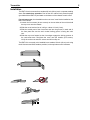
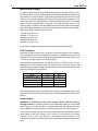
RMT-10 VHF
Rack-Mount Transmitter
Instruction Manual
099-0068D
2
Vega RMT-10
TABLE OF CONTENTS
Quick Start . . . . . . . . . . . . . . . . . . . . . . . . 2
A Word to Vega Users . . . . . . . . . . . . . . . . . . 2
Unpacking . . . . . . . . . . . . . . . . . . . . . . . . 2
Introduction . . . . . . . . . . . . . . . . . . . . . . . 4
Installation . . . . . . . . . . . . . . . . . .
Whip Antenna Length . . . . . . . . . .
XLR Connector. . . . . . . . . . . . . .
Power Supply . . . . . . . . . . . . . .
Adjustments . . . . . . . . . . . . . . . . .
Audio Compression Adjustment*. . . .
Audio Level Setting . . . . . . . . . . .
Frequency-Compensation Adjustments
Compatibility . . . . . . . . . . . . . . . . .
.
.
.
.
.
.
.
.
.
.
.
.
.
.
.
.
.
.
.
.
.
.
.
.
.
.
.
.
.
.
.
.
.
.
.
.
.
.
.
.
.
.
.
.
.
.
.
.
.
.
.
.
.
.
5
6
6
6
7
7
7
8
8
Frequency Selection. . . . . . . . . . . . . . . . . . . 8
Troubleshooting . . . . . . . . . . . . . . . . . . . . . 8
Antennas . . . . . . . . . . . . . . . . . . . . . . . 8
RF Noise . . . . . . . . . . . . . . . . . . . . . . . 9
Warranty (Limited) . . . . . . . . . . . . . . . . . . . 10
Factory Service Center . . . . . . . . . . . . . . . . 10
Claim . . . . . . . . . . . . . . . . . . . . . . . . . . 10
Specifications . . . . . . . . . . . . . . . . . . . . . 11
Quick Start
Please see Figure 1 and the instructions on the next page for a quick start.
A Word to Vega Users
In selecting Vega equipment, you are in the company of audio professionals
worldwide. Leadership for over 30 years has made “Vega” synonymous with wireless
equipment. Our equipment provides superb sound quality, outstanding performance,
and the durability needed for years of successful operation.
Unpacking
Verify the number of boxes shown as “shipped” has been received in good condition.
Unpack and save cartons for storage or reshipping. If, for any reason, you do not find
the equipment to be completely satisfactory, please immediately contact your Vega
dealer or the Vega factory.
Should service ever be required, remember your authorized Vega service dealer
knows your equipment best. They have the training and test equipment necessary to
restore your equipment to its peak performance.
Please feel free to contact either your authorized Vega dealer or the Vega factory for
information or assistance at any time.
Transmitter
5. Put on rack-mount (1a) “ears” or (1b) rubber feet (for details see “Installation”
next page).
6. Attach the whip antenna (see the “Whip Antenna Length” section) or the
optional dipole antenna to the ANTENNA connector on the rear panel.
7. Connect wall-type power supply to the rear-panel DC INPUT and then plug
the power supply into an ac outlet.
8. Connect audio source to the rear-panel XLR connector (see “XLR Connector"
next page).
9. Set the rear-panel INPUT LEVEL (MIC/LINE switch) to the LINE position.
10. Set the rear-panel AUDIO COMPRESSION switch to LINEAR.
11. Turn on the RMT-10 with the front-panel POWER switch.
12. With an audio input applied to the unit, adjust the front-panel INPUT LEVEL
ADJUST control until the AUDIO LEVEL bargraph meter indicates peaks in
the 0 to +2 VU range.
13. If the peaks do not reach at least 0 VU with the previous adjustment, set the
rear-panel MIC/LINE switch to MIC, then readjust the front-panel AUDIO
LEVEL control until the AUDIO LEVEL bargraph meter indicates peaks in the
0 to +2 VU range.
14. Attach an earpiece or headset to the receiver, turn on, select the correct
frequency, then verify correct reception. See the receiver's manual for details.
3
4
Vega RMT-10
Introduction
This document describes setup, adjustment, and operation only; detailed
maintenance information is not included. If you have any questions, consult your
dealer or the Vega factory.
Your Vega Model RMT-10 is a single-channel VHF FM transmitter. It transmits a mono
audio signal to compatible receivers (typically Vega PL-2s). The RMT-10's “transmitter
module” ( PCB) can be swapped (by authorized personnel) to allow operation on a
different frequency—any one of over 1,600 different frequencies between 169 MHz
and 216 MHz. Consult your dealer or the Vega factory for details.
The RMT-10 accepts either line or mic audio via a standard XLR connector. The “input
level” switch allows selection between mic (–40 to –10 dBu) or line (–10 and +20 dBu)
audio input. RMT-10s may also be internally programmed to work with Clear-Com or
RTS wired intercom systems (“receive-only” mode). The RMT-10 may also be
configured to pass a 70-volt speaker line (input up to 250 volts push-to-talk).
Fine audio-level adjustments may be made using the 30-dB variable attenuator
conveniently located on the front panel. To improve intelligibility, the transmission
signal may be adjusted via “frequency compensation” and “audio compression”
controls. Two “frequency compensation” controls for boosting or cutting the low and
high frequencies are provided on the rear panel. The “audio compression” control
limits dynamic range by either a 2:1 logarithmic compressor or a wide-range
automatic level control (ALC) system. See the “Adjustments” section for details.
Noise reduction is achieved with a proprietary two-ended compander system that is
always active. The compander is compatible with Vega's PL-2 portable VHF receiver.
A 1/4-wave “whip” antenna is provided with the RMT-10. Other antennas, such as the Vega
Model 123U dipole antenna, may be used to facilitate rack-mount installation or to improve
coverage where the standard whip antenna would otherwise be blocked or shielded by
equipment cabinets or large objects.
Transmitter
Installation
The RMT-10 can be mounted in a standard 19-inch (48-cm) rack, or operate standing
alone. For stand-alone operation: Peel off the four rubber feet's protective paper
(provided with the RMT-10) and attach to the bottom of the chassis at each corner.
For rack-mount use, the detachable rack-mount “ears” must first be installed on the
RMT-10 as follows:
1. Loosen the four screws (do not remove) on the two sides of the unit that hold
the top cover onto the chassis.
2. Slide the cover back as far as it will go—about 1/8 inch (3 mm).
3. Slide the smaller end of the front-mount ear into the grooves in each end of
the front panel. Be sure the ear's vertical locking groove is facing the unit's
rear.
4. Slide the top cover forward so the front edges engage the locking grooves in
the rack-mount ears. Re-tighten the cover onto the chassis (four screws).
Verify the rack-mount ears are secure and will not slip out.
The RMT-10 is now ready to be installed into a standard 19-inch (43-cm) rack using
the #10 screws and finish washers provided, or the equivalent metric hardware.
5
6
Vega RMT-10
Whip Antenna Length
For optimum antenna efficiency, the wire whip may be cut to length. Do NOT try to cut
the whip with wire cutters, the whip is made from tough steel and will likely destroy the
wire cutters. Use a bench grinder or equivalent to grind through the whip wire, being
careful to use protective goggles and heavy gloves while grinding operation. The
chart below lists the length required for various operating frequencies. The lengths
shown are for the exposed portion of the whip. The actual cut length will be 0.175"
(0.45 cm) longer. In addition, the values differ from the theoretical quarter wave length
due to the loading effects of the ball on the end of the whip and the connector barrel.
Approximate length of whip versus frequency:
170 MHz 17.8" (45.2 cm)
180 MHz 17.1" (43.4 cm)
190 MHz16.3"(41.4 cm)
200 MHz15.6"(39.6 cm)
210 MHz 15.0" (38.1 cm)
For frequencies between the chart entries, the length may be interpolated.
XLR Connector
Connect the system's audio source to the XLR connector located on the rear panel.
This is a balanced, transformer-isolated input, which is dc isolated to 50 volts. For the
standard mic-or line-level input modes, the pin assignments on this connector are: pin
1: shield, pin 2: audio positive, pin 3: audio negative.
When internally programmed for use with a Clear-Com or RTS intercom, the pin
assignments will be consistent with that required by the intercom system. The
programming jumpers are located inside the unit at the rear of the PCB, near the XLR
connector. Programming is as follows:
Mode
Balanced mic line
Clear-Com
RTS Channel
RTS Channel
70 Volt Live
JP1
BAL
XLR 3
XLR 2
XLR 3
70 V
JP2
BAL
XLR 1
XLR 1
XLR 1
70V
When reprogrammed, plug the wall-type power supply into a standard power outlet,
and insert the dc power connector into the power jack located on the rear panel of the
RMT-10.
Power Supply
WARNING: If providing dc power from another source, external fusing is
strongly advised. No internal circuit fuse is provided with the RMT-10. The provided
power supply is internally impedance- and thermal-limited and therefore does not
require additional circuit protection. Consult the Vega factory for more information.
You may wish to supply dc power from a source other than the provided wall-mounted
power supply. In this case, connect +12 to +20 Vdc (0.3 A minimum) to the power
connector on the rear of the RMT-10. A compatible mating connector is the
Switchcraft 760. When connecting external dc, carefully observe the following polarity
rules:
Transmitter
7
Power supply negative (–) to the outer conductor
Power supply positive (+) to the inner conductor
Adjustments
Note: Normal setup and operation does not require internal access. Refer all service
and internal adjustments to qualified service personnel. Specifically, the user may
not make adjustments to the transmitter module. See the “Troubleshooting” section
for additional information.
Use the same adjustment procedures for use with Clearcom, RTS, and 70-volt line
applications.
Audio Compression Adjustment*
The “Audio Compression" switch limits audio signal dynamic range as follows:
HARD ALC improves intelligibility by providing about 35 dB of automatic level control
with fixed gain at low input levels. SOFT ALC position provides soft, 2:1 logarithmic
gain compression—demphasizing louder audio while emphasizing low-level audio.
LINEAR does not alter the audio signal at all, and provides no dynamic range
adjustment.
Set the “LOW” and “HIGH” frequency compensation controls to the mid, or “0,”
position.
*The adjustment procedure for an intercom system or 70-volt line input is identical,
except the mic/line switch is not needed and is nonfunctional.
Note: Whenever a different dynamic-range setting is selected, it will be necessary to
readjust the variable audio level control to achieve the 0 VU reading on the frontpanel bargraph. If the VU meter consistently reads significantly lower than 0 VU,the
system will not be operating at the best possible signal-to-noise ratio.
Audio Level Setting
The RMT-10 accommodates audio levels between –40 dB to +20 dB, a 60 dB range.
If you know the approximate level of the input audio, set the mic/line as follows:
Program Audio Level
Mic/Line Switch Setting
–10 to +20 dBu
“LINE”
–40 to –10 dBu
“MIC”
Next, adjust the front-panel INPUT LEVEL ADJUST control until the front-panel VUmeter bargraph just reaches the “0 VU” position on voice peaks.
If you don't know the approximate level of the audio input, set the MIC/LINE
switch to LINE. Apply the desired program audio signal to the audio input connector.
Observe the front-panel VU meter. Adjust the front-panel variable audio level control
until the VU-meter bargraph just reaches the “0 VU” position.
If the VU meter bargraph consistently reads well below 0 VU, set the MIC/LINE
switch to the MIC position and readjust the variable audio level control for 0 VU
reading. If the VU-meter bargraph cannot be adjusted up to the 0 VU level with the
MIC/LINE switch in the MIC position, increase the audio level at the source.
8
Vega RMT-10
For use with Clearcom or RTS intercoms, or for 70-volt line applications, use the
same basic adjustment procedures as above.
Frequency-Compensation Adjustments
Listen to the program audio on a compatible receiver (Vega PL-2). Experiment with
the dynamic-range limiter settings and select the position that best meets your audioquality and intelligibility needs. The controls should be adjusted to achieve maximum
intelligibility for the particular listener group involved.
For the hearing impaired, a beginning setting of +5 to +6 for the “high” control, –4 to
–5 on the “low” control, and HARD ALC, is a good starting point.
These frequency compensation controls provide 10 dB adjustments to the low and
high frequencies, respectively. Unlike stereo tone controls, these adjustments affect
audio response well into the audio midrange.
Compatibility
The RMT-10 transmitter is intended to be used only with Model PL-2 portable
receiver(s) or other Vega receivers that are specifically identified as being compatible
with RMT-10.
Frequency Selection
For successful operation, it is necessary to choose a transmit frequency for the RMT10 that can coexist with other RF systems in the coverage area. The frequency of the
RMT-10 must be specified at the time of purchase. The Vega factory provides a
frequency-coordination service free of charge for this purpose.
NOTE: There are restrictions on use of specific frequency ranges by certain types of
users. If you do not understand these restrictions or are uncertain of their applicability,
consult your dealer or the Vega factory.
Troubleshooting
Most Vega equipment provides years of trouble-free operation. However, as with all
electronic devices, problems might occur. Problems are usually due to low batteries,
improper antenna placement, etc.—not equipment failure. Vega equipment is
thoroughly tested before leaving the factory.
The following paragraphs describe the most common problems. Please review this
information and take any necessary corrective action. If you still experience
difficulties, contact the Vega factory or your sales representative. Often, the problem
can be resolved by phone, avoiding downtime for unnecessary returns.
Should repairs be necessary within the first year of operation (under warranty), Vega
will promptly correct the problem and return the unit. Service for older units may also
be obtained from Vega; contact the factory or your sales representative for
information.
Return of both transmitter and receiver is recommended, allowing us to perform a
complete checkout and test of the entire system. This can be especially helpful for
elusive or intermittent problems.
Transmitter
Antennas
Proper mounting and placement of antenna(s) is vitally important in wireless systems.
If overlooked, antennas might cause unnecessary problems. In all cases, a clear and
unobstructed line-of-sight path between the transmitting antenna and the receiver(s) is
required.
The antenna might be concealed behind fabric, thin plastic, acoustic tile, and thin
plywood without significantly affecting performance. However, close proximity to
metallic objects such as furniture, lighting fixtures, scaffolding, electrical cables,
metal structural members, aluminum window frames, and equipment cabinets must
be avoided. Whip and dipole antennas require at least a 5-inch (0.1-m) minimum
spacing from metal surfaces. Other types of antennas may require greater spacing.
The manufacturer's recommendations should be followed when using yagis and
other types of specialized antennas.
9
10
Vega RMT-10
RF Noise
Problems with RF noise sources (fluorescent lights, car ignitions, industrial
equipment, etc.) are quite rare. Defective fluorescent lighting fixtures, however, can
generate significant amounts of RF energy. Usually, repairing the fixture will cure the
problem. This situation is true for most other interference sources as well. That is,
unless the equipment is electrically defective, the interference will not adversely affect
Vega wireless equipment.
Warranty (Limited)
All Vega wireless products are guaranteed against malfunction due to defects in
materials and workmanship for one year, beginning at the date of original purchase. If
such a malfunction occurs, the product will be repaired or replaced (at our option)
without charge during the one-year period, if delivered to the Vega factory. Warranty
does not extend to damage due to improper repairs, finish or appearance items,
malfunction due to abuse or operation under other than the specified conditions, nor
to incidental or consequential damages. Some states do not allow the exclusion or
limitation of incidental or consequential damages, so the above limitation might not
apply to you. This warranty gives the customer specific legal rights, and there may be
other rights which vary from state to state.
Vega authorized service centers enable Vega to give customers immediate service
on repairs. These service centers are fully qualified and equipped to handle the
servicing of Vega equipment, and turnaround time is excellent. To obtain the address
of your nearest authorized warranty service center, contact your dealer or the factory.
If you should require service, pack the equipment carefully and return it to the factory
service center or the nearest authorized service center.
Important: Be sure the exact return address and a description of the symptoms are
enclosed inside the package with your equipment.
It is also advisable to return the transmitter and receiver for full system performance
test when practical.
Factory Service Center:
Vega
9900 E. Baldwin Place
El Monte, CA91731-2294
Telephone: (626) 442-0782
Fax: (626) 444-1342
Faxback: (626) 444-2017
Claims
No liability will be accepted for damages directly or indirectly arising from the use of
our materials or from any other causes. Our liability shall be expressly limited to
replacement or repair of defective materials.
Transmitter
11
Specifications
Product Description: VHF audio transmitter
Frequency Control: Single frequency, crystal controlled
Frequency Stability: ± 0.005%
Operating Frequency Range: 169-216 MHz
RF Power Output: 50 mW, maximum
Modulation: Direct FM, 45K0F3E
Maximum Deviation: ± 7.5 kHz
Deviation Limiter Range: Frequency-compensated active rectifier, voltagecontrolled amplifier
Balanced Audio Input (Mic/Line Mode): 3-pin female XLR; 1-ground, 2-audio +, 3-audio −
Audio Input Level Select : Rear-panel-mounted slide switch
Audio Input Level: LINE: –10 to +20 dBu;
MIC: –40 to –10 dBu;
70 volt: 3 to 80 volts RMS
Audio Input Adjust Range: 30 dB nominal
Audio Frequency Compensation Adjustments: Low ±10 dB; high ±10 dB
Audio Frequency Response: 120 Hz to 10 kHz ±2 dB (frequency controls electrically
centered)
Noise-Reduction System: Two-ended 2:1 logarithmic companding
User-Selectable Audio Processing: Hard ALC (35 dB range) or
soft ALC (2:1 compensated logarithmic compressor)
User-Accessible Controls and Indicators: Front Panel: power on/off switch; power-on LED; audio
input level adjust; VU meter (8-segment LED).
Rear Panel: audio input connector (3-pin XLR female);
audio-processing switch (3-position: hard ALC, linear,
soft ALC); audio input level: (2-position: mic or line);
frequency compensation (two screwdriver-adjustable
controls, high and low); dc power input; RF output (SO239)
Power Required: +12-20 V,5,0,0,0,0dc, 300 mA, maximum, negative
ground
Power Supply Provided: Wall-mount, 12 Vdc, 500 mA, unregulated (120 Vac
standard, 240 Vac optional)
Packaging: 19 in (48 cm) rack mount; 17 in (43 cm) W × 1.72 in (4.4
cm) H × 5.1 in (13 cm) D, excluding detachable rackmount ears
Weight: 3.2 lb (1.5 kg), without power supply
www.vegawireless..com
9900 East Baldwin Place • El Monte, California 91731-2294
Telephone: (626) 442-0782 • Toll-Free: 800-877-1771
Fax: (626) 444-1342 • CompuServe: 73513,1417
© Vega April 2000