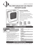
1
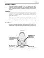
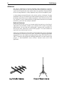
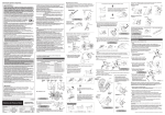
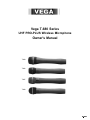
Vega T-680 Series
UHF PRO-PLUS Wireless Microphone
Owner's Manual
T-689
T-682
T-687
T-688
099-0054B
2
T-680 Series
A Word to Vega Users
In selecting Vega wireless microphones, you are in the company of audio
professionals worldwide. Leadership for over 30 years has made “Vega”
synonymous with wireless microphones. Vega equipment provides superb sound
quality, outstanding performance, and durability needed for years of successful
operation.
Unpacking
Unpack and save cartons for storage or reshipping. Verify the equipment shown as
“shipped” has been received in good condition. If, for any reason, you do not find the
equipment to be completely satisfactory, please immediately contact your Vega
dealer or the Vega factory.
Should service ever be required, remember your authorized Vega service dealer
knows your equipment best. They have the training and test equipment necessary to
restore your equipment to its peak performance. Please feel free to contact either
your authorized Vega dealer or the Vega factory for information or assistance at any
time.
Quick Start
See below for a description of transmitter controls and the next page for setup. If this
is the first time you are setting up a wireless system, carefully read all manuals
furnished with your equipment to ensure optimal performance.
Windscreen
Microphone Switch: Turns
mic audio on\off without
turning transmitter off. Audio
is on when switch is pushed
toward the dot.
Mic Gain Control: Set
so corresponding
receiver's VU meter
nominally reads “0” on
audio peaks.
Power Switch: Turns
power on and off.
Power is on when
switch is pushed
toward the dot.
Audio Peak LED:
Flashes on audio peaks;
indicates audio limiter
has been activated due
to high sound levels.
Wireless-Microphones
1
Unlatch cover and insert a 9-volt battery.
Slide 9-volt battery into compartment with the plus
“+” terminal as shown above. Slide cover back
on.
3
In the area covered by the wireless system,
verify the receiver is receiving by observing
its indicators (see receiver instructions for
details).
5
Adjust mixer/preamp/amplifier to its normal
setting. Speak into mic. If necessary, adjust
receiver's audio output level until wireless system
volume matches wired system volume (see
receiver instructions for details).
3
2
Turn the transmitter Power “P” on and
Microphone “M” on by sliding the switches
toward the dots.
4
With a small screwdriver, adjust transmitter
mic level so the receiver's “AUDIO LEVEL”
LED flashes only when speaking very loudly.
If it flashes frequently, turn it counterclockwise. If
it doesn't flash at all, turn it clockwise.
6
“Walk” the coverage area to check for
problems. If there is a problem, check mic
batteries (fresh?); ensure antennas aren't
touching each other or any metal objects. Path
between transmitter and receiver must be clear
for proper operation.
4
T-680 Series
Compatibility
T-680 Series mics are designed to work with Vega's Model 662 Series receivers. T680s are not necessarily compatible with other receivers, especially if not purchased
together.
System receivers must use DYNEX®III audio processing and use precisely the same
frequencies as the transmitters. The transmitters are not compatible with other
manufacturers' receivers.
T-680 Series mics work in the 494 to 608 MHz and 614 to 806 MHz UHF range. The
exact frequency is marked on the data label inside the transmitter's battery
compartment. If the transmitter and receiver frequencies are not precisely the same,
the frequency of one of the units must be changed. It's advisable to return both units
to the factory or authorized service location when changing frequencies, to ensure
the best results. Because of the very high performance of these units and the
specialized test equipment required to adjust them properly, users should not try to
change frequency themselves.
If two or more systems are used at the same location, proper frequency selection and
spacing are required to avoid possible interference.
Vega offers a free frequency-coordination service for purchasers of its equipment.
Frequencies are selected by computer to avoid any possible interference from other
wireless systems and broadcast stations. To take advantage of this free service,
contact the Vega factory or your local sales representative (phone number on last
page of this manual).
The T-680 Series professional handheld transmitters are self-contained units and
require only a battery and a compatible receiver for operation. Individual models in
the T-680 Series each use different types of microphone elements, leading to some
differences in physical appearance between the various models. However, all
transmitters in this series are functionally equivalent, and the operation instructions
below and other information in this manual are applicable to all models.
Because of the acoustic characteristics of the various types of microphone elements,
individual models in this series may sound significantly different from other models.
These differences are entirely due to the microphone element; all models offer
identical performance, otherwise.
Wireless-Microphones
Operating Instructions
(1) Verify that the associated wireless-microphone receiver is on the exact same
frequency as the T-680 Series transmitter to be used.
(2) Set up, adjust, and connect the receiver as described in its instruction manual.
(3) Verify that the transmitter's battery is fresh.
(4) Turn on the transmitter via the switch on the bottom (toward the dot). The LED
indicator should flash briefly upon turn-on; this indicates that the battery is installed
properly.
NOTE: The LED does not provide an indication of battery condition. If there is any
question as to the condition of the battery, it should be replaced prior to use of the
transmitter.
(5) Turn “on” the microphone in the transmitter via the switch on the bottom of the
unit (toward the dot). Make an initial adjustment of the microphone gain control of
about one-quarter turn from the minimum (fully counterclockwise) position.
(6) With the receiver and transmitter on, the “SQUELCH” indicators on the receiver
should be illuminated. Observe the RF-level meter (or bargraph) on the receiver. If
the meter does not read well above midscale when the transmitter is within a clear
50-foot radius of the receiver, difficulties are indicated (refer to section “In Case of
Difficulty”).
(7) Speak into the microphone at normal voice level. The audio meter on the
associated receiver should indicate audio on voice peaks, and the audio should be
audible on the associated monitoring equipment. The audio may also be monitored
on headphones plugged into the receiver “monitor” jack.
(8) Adjust the transmitter audio gain control, if necessary. When speaking or singing
very loudly, the LED on the transmitter should flash “on” only on the very loudest
voice peaks. This indicates that the transmitter is reaching the point where soft gain
compression is occurring in the microphone preamplifier. If the system is correctly
set up, the compression point will be reached only rarely.
Internal adjustments are not required for normal operation. Only qualified
experienced technicians should open the case. Unauthorized adjustments or repairs
inside the equipment case can void your warranty and cause unnecessary repair cost.
If you feel that internal adjustments or repairs are needed, we recommend you
contact the factory or your nearest authorized service center.
(10) “Walk” the coverage area to ensure that there are no areas of poor coverage.
Signal “dropouts” (little or no signal in small areas) show up as a flickering of the
“SQUELCH” indicator on the receiver and a brief “fizzing” sound in the audio (which
may or may not be followed by a silent period due to squelched audio). The audio may
be conveniently monitored with headphones plugged into the front-panel
“MONITOR” jack on the receiver. If there is an area where a “dropout” occurs, the
receiving antenna(s) can usually be repositioned to eliminate the problem. Frequently,
a change of just a few inches in location will completely solve the problem.
5
6
T-680 Series
Antennas
The receiver antenna may be the most important single component in a wirelessmicrophone system. However, this is the item most often overlooked in setting up a
system, and is frequently the cause of quite unnecessary problems. Proper placement
of the receiving antenna(s) is vitally important in any wireless-microphone system.
A whip antenna connected directly to the wireless receiver is adequate for many
installations. This type of antenna is provided with the R-662 Series receivers. When
the distance between the receiver and the transmitter is 100 to 200 feet (30-60 m) or
less, and there is a clear, unobstructed line-of-sight path between the receiver and the
transmitter, good results can usually be obtained.
Optional Antennas
If you wish to have the receiver in a location which does not have a clear line-ofsight path to the transmitter, another type of antenna will be needed. Vega offers
magnet-mount 1/4-wave-whip and “ground-plane” antennas with an attached 15foot (4.6-m) cable, which may be used for this purpose. Two such antennas are
required for use with diversity receivers.
Other types of antennas may be needed for unusual applications, such as operating at
extreme ranges of 500 feet (150 m) or more. Vega offers a high-gain log-periodic
antenna that covers the complete operating-frequency range of the R-662 receiver.
UHF TV antennas (with appropriate matching transformers) are often used for this
purpose. A wide-bandwidth “corner reflector” antenna works well in this
application.
Wireless-Microphones
UHF communications antennas are also sometimes used for specialized
requirements. However, such antennas are usually narrow band and must be
modified to function properly in the 494 to 608 MHz and 614 to 806 MHz ranges.
Contact the Vega factory or your sales representative for assistance in selecting
antennas for unusual applications.
Antenna Placement
No matter what type of antenna is used, care must be used in positioning and
mounting. In all cases, a clear and unobstructed line-of-sight path between the
receiving antenna and the transmitter is required. The receiving antenna may be
concealed behind fabric, thin plastic, acoustic tile, and thin plywood without
significantly affecting performance. However, close proximity to metallic objects
such as furniture, lighting fixtures, scaffolding, electrical cables, metal structural
members, aluminum window frames, and equipment cabinets must be avoided.
Whip and dipole antennas require at least a 5-inch (0.13-m) minimum spacing from
metal surfaces. Other types of antennas may require greater spacings. The radiation
pattern of these antennas is much larger than the antenna itself. Consequently, even
objects well off to one side of the line-of-sight path can distort the antenna pattern,
affecting performance. Also often overlooked are the effects of using metal brackets
for physical mounting of the receiving antenna. Vega's magnetic-mount and groundplane antennas are designed to mount on a flat metal plate and on an antenna mast,
respectively, but many types of antennas are not. The manufacturer's
recommendations should be followed when using Yagis and other types of
specialized antennas.
The use of long cables connecting the antenna to the receiver is strongly
discouraged. At UHF frequencies, the signal loss in the cable rapidly builds up and
can seriously degrade operating range.
7
8
T-680 Series
In Case of Difficulty
The majority of difficulties with Vega wireless mics are not due to equipment
failure. Vega equipment is fully tested before leaving the factory. In most instances,
problems are due to equipment application.
The following paragraphs describe the most commonly encountered application
problems. If you are having difficulties with Vega equipment, please review this
information and take any necessary corrective action prior to returning the
equipment for repair.
Most users of Vega equipment enjoy years of troublefree operation. However, as
with all electronic devices, problems might be encountered eventually. If you
experience difficulty with your Vega wireless microphone within the first year of
operation, it will be repaired under warranty (see below). Service for older units may
also be obtained from Vega; contact the factory or your sales representative for
information.
General
Contact the Vega factory or your sales representative prior to returning equipment
for repair. Often, the problem can be resolved by phone, avoiding downtime for
unnecessary returns. However, should repairs be necessary, Vega will promptly
correct the problem and return the unit. Return both the transmitter and the receiver,
to allow us to perform a complete checkout and test of the entire system. This can be
especially helpful for elusive or intermittent problems
Battery
The most common problems with wireless-microphone systems are those related to
the batteries. Vega recommends that only new, fresh Duracell MN1604 or
“Eveready” Energizer No. 522 alkaline batteries be used. No other batteries tested by
Vega provide equal life and reliability. Other batteries might work, but battery life
probably will be short and current inadequate.
Rechargeable batteries (“ni-cads”) are not recommended for use with T-680
transmitters. Their limited capacity does not provide adequate operating time.
Exhausted batteries will cause numerous problems, including distortion, audible
squeals and howls, poor range, and off-frequency operation. It is strongly
recommended that the battery be checked prior to each use, and that it be replaced if
there is any question about its condition. It is also good practice to try replacing the
battery with a fresh unit in the event of any sort of problem with the system, because
a low battery might affect system operation in subtle ways.
Battery contacts must be clean and unbroken. Attempted forced reverse insertion of
a battery is practically impossible, but the attempt will often damage the battery
contacts. Some “9-volt” batteries sold are larger (or smaller) than standard and either
might fail to work or might damage the contacts when inserted. Damage to the
contacts usually requires a return to the factory or authorized service center.
Wireless-Microphones
9
Interference
Vega wireless-microphone systems have been specifically designed to reject
interference. However, interfering signals might fall directly on the receiver
frequency, making it impossible to avoid problems completely. As mentioned
above, this can be a particular problem if the receiver audio is left open when the
transmitter is turned off.
Problems with RF noise sources (fluorescent lights, digital effects generators,
industrial equipment, etc.) are quite rare. However, defective fluorescent lighting
fixtures can generate astonishing amounts of RF energy. Usually, repairing the
fixture will cure the problem, because normally functioning fixtures almost never
cause trouble. Some digital audio and video signal-processing equipment and effects
generators also can generate substantial amounts of broadband noise. When this
situation exists, nothing can be done to the wireless equipment to correct the problem
that will not seriously degrade performance. The receive antennas should be
positioned away from these sources of RF noise to minimize the effect of this
interference. Fortunately, this type of problem is surprisingly rare.
A more serious problem is selection of wireless-microphone operating frequencies,
which are inherently subject to interference due to intermodulation. Fortunately, a
proper initial selection or changing frequencies will almost always correct any such
problem.
Vega offers a free computerized frequency-selection service to purchasers of our
equipment. If the frequency of other wireless equipment to be used in a given area is
known, interference-free frequencies can be chosen. However, if equipment is added
later without frequency coordination, it is likely that an interference problem will
exist. Should this occur, contact the Vega factory or your sales representative for
assistance. Many individuals believe that only a few wireless systems may be used in
an area. This is incorrect, because installations with a dozen or more wireless
systems are not uncommon. However, careful frequency coordination is essential.
Common Sources of Interference
10
T-680 Series
Receiver Noise
Vega wireless microphone receivers are designed to be extremely sensitive.
Although high-performance squelch circuits are provided, it is not unusual for the
receiver squelch to open and let through audio noise when the transmitter is off. This
is usually due to spurious outputs from two-way radio transmitters, adjacent-channel
leakage from TV transmitters, and, in some cases, RF noise from digital equipment
such as audio and video effects generators, computers, and other industrial
equipment that might be located near the antennas. When the wireless transmitter is
“on,” this noise is suppressed and rarely causes any difficulties. However, if the
audio channel is left “open” with the transmitter “off,” loud blasts of noise might
occur. For this reason, it is advisable to “fade” the receiver audio when the
transmitter is not in use. Changing the placement of the antennas and, in some
extreme cases, changing the operating frequency might be necessary to minimize
these problems.
Antennas/Cables
As noted in the section on antennas above, antenna placement and mounting are
vitally important. Blocking the antenna with metallic objects reduces the signal level
and might cut off the signal entirely (pattern “nulls”). If there is a coverage problem,
try moving the receiving antenna, particularly if there are nearby metallic materials.
Vega FaxBack
Information including more detailed procedures, schematics, and other Vega
products is available 24 hours per day from Vega's FaxBack system. Simply call
(626) 444-2017 or 800-274-2017, then follow the voice instructions.
Warranty (Limited)
All Vega PRO PLUS wireless products are guaranteed against malfunction due to
defects in materials and workmanship for one year, beginning at the date of original
purchase. If such a malfunction occurs, the product will be repaired or replaced (at our
option) without charge during the one-year period, if delivered to the Vega factory.
Warranty does not extend to damage due to improper repairs, finish or appearance items,
malfunction due to abuse or operation under other than the specified conditions, nor to
incidental or consequential damages. Some states do not allow the exclusion or
limitation of incidental or consequential damages, so the above limitation may not apply
to you. This warranty gives the customer specific legal rights, and there may be other
rights which vary from state to state.
Vega authorized service centers enable Vega to give customers immediate service
on repairs. These service centers are fully qualified and equipped to handle the
servicing of Vega equipment, and turnaround time is excellent. To obtain the address
of your nearest authorized warranty service center, contact your dealer or the factory.
If you should require service, pack the equipment carefully and return it to the
factory service center or the nearest authorized service center.
Wireless-Microphones
Important:
Be sure the exact return address and a description of the symptoms are enclosed
inside the package with your equipment.
It's also advisable to return the transmitter and receiver for a full system performance
test when practical.
Factory Service Center:
Vega
9900 E. Baldwin Place
El Monte, CA 91731-2294
(626) 442-0782
Claims
No liability will be accepted for damages directly or indirectly arising from the use
of our materials or from any other causes. Our liability shall be expressly limited to
replacement or repair of defective materials.
11
12
T-680 Series
T-680 Series Transmitter Specifications
Operating Frequency:
Emission/Modulation:
RF Frequency Stability:
RF Output Power:
Spurious Radiation:
Audio Processor:
Acoustic Input Range:
Controls:
Indicator:
Modulation Limiting (Compressor):
Antenna:
494-608, 614-806 MHz
Direct FM, crystal controlled, 180KF3E; 75-kHz maximum deviation
±0.002%
150 mW, nominal or 40 mW nominal, depending on version
40 dB below carrier, minimum; typically 50 to 55 dB below carrier
DYNEX®III
At maximum gain typically 112 dB SPL for onset of compression; maximum
acoustic input: 143 dB SPL
Power on/off, microphone on/off, microphone gain
Audio compression
Per FCC requirements; “soft” compressor action, 25 dB range; typically system
distortion is less than 0.4% at 25 dB compression
Patented* Internal dipole
Battery:
9-V alkaline, Duracell MN1604 recommended
Length:
Varies by model, from 9.85 in (25 cm) to 10.75 in (27.3 cm)
Weight:
Varies by model, from 9 oz (256 g) to 13.5 oz (385 g), including battery
UHF PRO PLUS System Specifications
with R-662A or R-662B receivers
Working Range: 1,700 ft under good conditions; 500 ft or more under typical conditions with
standard whip antennas
Audio Frequency Response:
Depends upon microphone element and electronics; 90 Hz to 15 kHz, ±1.5 dB, 120
Hz to 12 kHz, ±0.75 dB (units include highpass filter to minimize handling noise;
extended low-frequency response available on special order)
Total Harmonic Distortion:
<0.25%, 400 Hz, nominal input level
Intermodulation Distortion:
<0.25% (SMPTE 60/7,000 Hz, 4:1)
Ultimate S/N:
Dynamic Range:
*
Microphone off: 101 dB (flat), minimum; 108 dB typical, A-weighted. Microphone
on: varies by element type and gain setting, typically over 100 dB (A-weighted) at
normal gain settings.
Varies by element type and gain setting; typically over 100 dB; over 125 dB with
gain adjustment
Patent #4,344,184 issued August 10, 1982
www.vegawireless.com
9900 East Baldwin Place • El Monte, California 91731-2294
Telephone: (626) 442-0782 • Toll-Free: 800-877-1771
Fax: (626) 444-1342 • CompuServe: 73513,1417
FaxBack: (626) 444-2017 • Toll-Free FaxBack: 800-274-2017
Printed in U.S.A.
©April 2000 Vega