1
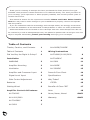
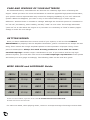
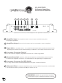
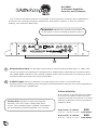
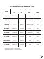
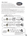
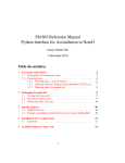
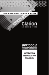
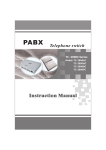
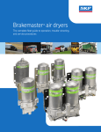
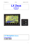
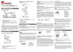
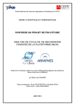
www.usamps.com
AX series
Owners Manual
and
Installation
Guide
Copyright 2007 U.S.Amps. All rights reserved.
Thank you for choosing U.S.Amps! You have purchased the finest product of its type
available. Each product is tested and built in our California factory. You won’t just listen to
your U.S.Amp; you’ll experience it. When properly installed, this unit will provide years of
trouble-free service.
This manual is written for the experienced installer. Please read it ALL before installation! You may need to make changes in your installation to properly connect and operate
this fine product.
If you are unfamiliar with the terminology and concepts within, we strongly recommend
you seek the assistance of an Authorized U.S.Amps Dealer or other car audio professional.
Authorized Dealers can be located on the U.S.Amps' web site: www.usamps.com. We can
be reached by e-mail at [email protected], but please be patient with us and give us a few
days to respond. Remember, protect your hearing and enjoy your U.S.Amps!
Table of Contents
Thanks, Caution, and Contacts
1
Table of Contents
1
Did You Buy the Right U.S.Amp?
2
Installation
8
Wiring Instructions
AX-TU600C/1000/2000
9
AX-TU4360C
10
WARNING
2
AX-5600
11
Amplifier Mounting
2
AX-600DE
12
Ventilation
2
AX-3200DE
13
Amplifier and Crossover Input
2
Power & Fuse Chart
14
Signal Level Input
2
Specifications
15
Gain Control Adjustment
2
Why Tubes?
16
Batteries
3
VTCSD
16
Getting Wired
3
Amplifier Controls & Features
1
AX-600DE/3200DE
Benefits of Class “DE”
17
Note
18
AX-TU600C
4
Never, Never, Never!
BACK
AX-1000/2000
5
Warranty
BACK
AX-TU4360C
6
AX-5600
7
Did You Buy the Right U.S.Amp?
There is a U.S.Amp for every purpose! From raw power to exquisite sound quality and everything
in between, U.S.Amps offers state-of-the-art technology to meet your every need.
INSTALLATION
Amplifier Mounting: Choose an appropriate location to mount the amplifier(s). Make
sure your choice is free from excess heat, moisture, and vibration. Under the vehicle seat or in the
trunk are common mounting locations. Be sure the amplifier receives adequate ventilation to its
heat sink and is positioned away from flying luggage and people’s feet. Do not mount to the
speaker enclosures.
Ventilation:
It is important to provide the amplifier with adequate ventilation to remove
heat from the amplifier heat sink. During high performance applications, in which the amplifier
may be exposed to extremely low impedance loads, it may be necessary to provide external
ventilation via a fan or some other means. With proper ventilation, the "run time" of the amplifier
between thermal protection cycles can be greatly extended.
IMPORTANT NOTICE
The Input of a U.S.Amp MUST be GROUNDED for proper amplifier operation.
The use of external ground isolation dividing devices is UNNECESSARY
and may cause severe amplifier and/or system damage.
Amplifier Input:
U.S.Amps feature a unique isolated input section that will accept
signal voltages from 1 to 9 volts. The input section also provides amplifier ground isolation for the
prevention of system and engine noise. The unique configuration of the U.S.Amps input necessitates a correct input ground, and is not compatible with external ground isolation devices.
Signal Level (BTL) Input:
This product will accept line and signal level, and can be
used with most BTL "high powered" sources. To use a BTL source, observe the following:
1) BTL outputs have two "hot" non-grounded leads per channel. Select ONE per channel, and
connect it to the “center conductor” of the RCA input cables going to the amplifier input.
2) Insulate and disregard the second wire of each BTL output pair.
3) Ground the shield wires of the RCA cable to the metal body of the source unit.
Gain Control Adjustment:
Always start with the gain control fully counter-clockwise
(all the way down), or just slightly open. Adjust the source unit volume as high as possible without
distortion. Increase the amplifier gain until the amplifier distorts, then turn the gain down slightly
until the signal becomes clear. It is desirable to operate the amp at the lowest possible gain setting
to help reject spurious system noise.
2
CARE AND FEEDING OF YOUR BATTERIES
As mentioned before, most batteries are built for the relatively light chore of starting the
engine. Unless you have the room and ambition to install an upgraded high-powered alternator,
your system current requirements may exceed the charging capability of your car’s electrical
system. When this happens, you have to rely on the vehicle battery(s) to make up the
difference. Another factor to consider is voltage. Although the electrical system is considered to
be “12 volt”, the battery, when healthy, actually “rests” at 12.6 volts. The average alternator
“puts out” 14.4 volts when the engine is on, because it is necessary to “feed” a battery higher
voltage in order for it to charge.
GETTING WIRED:
Once you have established the current needs of your system, it will be of the UTMOST
IMPORTANCE to properly fuse the amplifier. Remember, power connections are always the last
thing. There cannot be enough emphasis placed on the importance of proper fusing. Fuses
prevent catastrophes. Always fuse each U.S.Amp product at or less than the recommended amperage. Another major consideration is wire. If you wish to build a truly highpowered system, you must take into account the total amperage requirements of the system
and select your wire gauge accordingly. The following chart can be used as a guide:
WIRE GAUGE and AMPERAGE Guide:
AWG 14
30 Amps
AWG 6
80 Amps
AWG 0
190 Amps
AWG 13
35 Amps
AWG 4
105 Amps
AWG 00
215 Amps
AWG 10
45 Amps
AWG 2
135 Amps
AWG 000
245 Amps
AWG 8
60 Amps
AWG 1
160 Amps
AWG 0000
275 Amps
These are real numbers, right out of the 1951 U.S.Federal Electronics Code Book.
It takes real wire to do real work.
For each 100 watts, when playing music, count on 10 amps average of average current draw.
3
AX-TU600C
2-Channel Amplifiers
Controls and Features
1
2
3
4
5
6
Full
L
Min
50
500
INPUT SUB
Gain Freq RBG
R
In
Out
HP
8
7
LP
SUB
XOver
Off
On
Pwr Prot
50
500
Subsonic HP
Filter Freq
AX-TU600C
X-TU600C
“VTCSD” Technology
U.S.A.
1 Amplifier Input The amplifier MUST receive input on BOTH RCA jacks
for proper operation.
2 Amplifier Output The low level output can be connected to other amplifiers.
3 Input Gain is variable from 1 to 9 volts for full output. Best results are achieved by
adjusting the control to the lowest setting in relation to the output of the source unit.
4 Low-pass Crossover Control
For the internal amplifier, adjustable from 50 Hz to 500 Hz @ 24dB.
5 Remote Bass Gain A phone jack that accepts the included RBG control harness
to allow the amplifier volume to be controlled from the passenger compartment.
6 Low-pass Crossover 3-way Switch
A 3-way switch which selects the full-range/high-pass/low-pass crossover feature.
7 Subsonic Filter To optimize amplifier power in the audible frequencies, a defeatable
36 Hz subsonic filter provides a 6 dB per octave roll-off.
8 High-pass Crossover Control
For the internal amplifier, adjustable from 50 Hz to 500 Hz @ 12dB.
WARNING: All U.S.Amps require a grounded input connection.
DO NOT use ground-loop isolation devices or high/low conversion devices
on the input of your U.S.Amp!
4
AX-1000/2000
2-Channel Amplifiers
Controls and Features
1
2
3
4
5
6
Off
7
On
Off
On
L
Pwr Prot
Min
50
500
INPUT SUB
Gain Freq RBG
R
In
SUB
XOver
AXX-1000
Out Two Ohm Stable Design
Subsonic
Filter
U.S.A.
(Shown here is AX-1000, but the diagram is also applicable to AX-2000.)
1 Amplifier Input The amplifier MUST receive input on BOTH RCA jacks
for proper operation.
2 Amplifier Output The low level output can be connected to other amplifiers.
3 Input Gain is variable from 1 to 9 volts for full output. Best results are achieved by
adjusting the control to the lowest setting in relation to the output of the source unit.
4 Low-pass Crossover Control
For the internal amplifier, adjustable from 50 Hz to 500 Hz @ 24dB.
5 Remote Bass Gain A phone jack that accepts the included RBG control harness
to allow the amplifier volume to be controlled from the passenger compartment.
6 Low-pass Crossover On/Off Switch
A 2-way switch which enables/disables the low-pass crossover feature.
7 Subsonic Filter To optimize amplifier power in the audible frequencies, a defeatable
36 Hz subsonic filter provides a 6 dB per octave roll-off.
WARNING: NEVER use ground-loop isolation
on the input of your U.S.Amp! It doesn’t need it!
5
AX-TU4360C
4-Channel Amplifiers
Controls and Features
The AX-4360C features a selectable two-way electronic crossover with independent
front and rear mid-high frequency adjustment and 2 ohm per channel stability. Power is
provided by four 75 watt channels that can be bridged as front and rear pairs into a 4
ohm load for a total of 180 watts per bridged pair.
WARNING: NEVER use ground-loop isolation
on the input of your U.S.Amp! It doesn’t need it!
2
1
Front
Gain
3
Rear
Gain
Front
Freq
Rear
Freq
5
4
SUB
Freq
L
LP HP Full
LP HP Full
Pwr Prot
Max
Max 50 500 50 500 50 500
Front
Rear
AX-TU4360C
X-TU4360C RBG
R
Front Rear
Input Input
Four Channel Amplifier
U.S.A.
1 Amplifier Input The amplifier MUST receive input on BOTH RCA jacks
for proper operation.
2 Input Gain is variable from 1 to 9 volts for full output. Best results are achieved by
adjusting the control to the lowest setting in relation to the output of the source unit.
3 Low-pass Crossover Control
For the internal amplifier, adjustable from 50 Hz to 500 Hz @ 24dB.
4 Remote Bass Gain A phone jack that accepts the included RBG control
harness to allow the amplifier volume to be controlled from the passenger compartment.
5 Low-pass Crossover 3-way Switch
A 3-way switch which selects the full-range/high-pass/low-pass crossover feature.
6
AX-5600
5-Channel Amplifier
Controls and Features
The 5-channel AX-5600 features a selectable 3-way electronic crossover with independent
front and rear mid-high frequency adjustment, dual power supplies, 2 ohm per channel
stability, and a Remote Bass Gain.
WARNING: NEVER use ground-loop isolation
on the input of your U.S.Amp! It doesn’t need it!
1
Sub
Gain
Sub
XOver
Band
Pass
Rear
Gain
Rear
HP
Front
Gain
L
L
Min
R
SUB Input
50 500
RBG
200 5K
50 500
Rear LP
XOver
Rear HP
XOver
AX-5600
Five Channel Amplifier
DE Sub Channel
Max
50 500
Max
Front HP
XOver
Pwr
R
U.S.A.
Rear
Input
Front
Input
2
1
Remote Bass Gain The AX-5600 comes with an optional “Remote Bass Gain” or “RBG” that
can be mounted in the passenger compartment to independently attenuate the low pass output.
The “BASS GAIN” located on the terminal endplate of the unit is used both to set the level at the
low pass output and control the range of the RBG.
2
3-WAY Input allows the AX-5600 to accept input from modern 3-way head-units
allowing front to-rear fading of the mid-highs and Independent frequency and volume adjustment
from the passenger compartment.
2 Ohm Stability
Protection AX-5600 is protected against
thermal, over and under voltage and short
All 5 channels of the AX-5600 are stable
to 2 ohms. The power of the mid-high
channels increase 17% from 4 to 2 ohms
while the subwoofer channel increases a
whopping 43%!
circuit. The separate power supplies of AX-5600
are individually protected against over-current.
Amp Power @ 4 Ohms
75 W X 4 + 500 W X 1 @ 1Ω
Amp Power @ 2 Ohms
90 W X 4 + 500 W X 1 @ 1Ω
7
800
Total Watts
860
Total Watts
AX-600DE/3200DE
Class “DE” Amplifiers
Controls and Features
1
2
3
5
4
Subsonic
L
R
INPUT
PWR Prot
Min
INPUT
Gain
50
500
SUB
Freq
XOver
RBG
AX-600DE
One Ohm Stable Design
Slave
Class DE Digital Amplifier
U.S.A.
1200 Watts Dynamic Power
600 Watts RMS Power
(Shown here is AX-600DE, but the diagram is also applicable to AX-3200DE.)
1 Amplifier Input The amplifier MUST receive input on BOTH RCA jacks for proper
operation.
2 Input Gain is variable from 150 mV to 3 volts for full output. Best results are achieved
by adjusting the control to the lowest setting in relation to the output of the source unit.
3 Low-pass Crossover Control
For the internal amplifier, adjustable from 50 Hz to 500 Hz @ 24dB.
4 Remote Bass Gain A two-position removable plug that accepts the included RBG
control harness to allow the amplifier volume to be controlled from the passenger
compartment.
5 The Magic Switch
The far left "Subsonic Filter" position makes more efficient use of amplifier
power by discarding frequencies below 36Hz.
The center "XOver" defeats the Subsonic Filter tor amplifier operation down to 5 Hz.
The far right "Slave" position defeats all amplifier controls to receive information through the Remote
Bass Gain wires from another "master" amplifier.
This can be repeated as often as necessary with all slave units receiving Identical gain, frequency, and
subsonic functions from the master amplifier.
A single Remote Bass Gain can be connected at any point to universally control the volume of the
entire amplifier bank.
WARNING: All U.S.Amps require a grounded input connection.
DO NOT use ground-loop isolation devices or high/low conversion devices
on the input of your U.S.Amp!
8
Wiring Instructions for AX-TU600C/1000/2000
Power Output
+
–
AX-TU600C
165W X 2 @ 4Ω
300W X 2 @ 2Ω
AX-1000
300W X 2 @ 4Ω
500W X 2 @ 2Ω
AX-2000
600W X 2 @ 4Ω
1000W X 2 @ 2Ω
–
+
LEFT
[—]
RIGHT RIGHT
[—]
[+]
+ +
+
+
LEFT
[+]
Source Unit
+
–
Positive 12V Remote Turn-on
Bridged Output
Fuse Rating
REM
Positive 12V to Vehicle Battery
(Use minimum 4-gauge Wire)
+
+
12V
POS
GND
+ +
AX-TU600C:
AX-1000:
AX-2000:
Negative 12V to Vehicle Ground
(Use minimum 8-gauge Wire)
F
U
S
E
−
WARNING: NEVER use ground-loop isolation
Vehicle Battery
11 to 15 volts DC
9
60A
100A
200A
AX-TU600C
600W X 1 @ 4Ω
AX-1000
1000W X 1 @ 4Ω
AX-2000
2000W X 1 @ 4Ω
Vehicle Ground
on the input of your U.S.Amp! It doesn’t need it!
Wiring Instructions for AX-TU4360C
Source Unit
WARNING: NEVER use ground-loop isolation
on the input of your U.S.Amp! It doesn’t need it!
Positive 12V Remote Turn-on
Front Left
Speaker
GND
+
+ +
–
FL
[+]
FR
[—]
RL
[+]
RR
[—]
+
RL
[—]
+
FR
[+]
+ +
Power Output
+ +
RR
[+]
75W X 4 @ 4Ω
90W X 4 @ 2Ω
+
F
U
S
E
FL
[—]
Negative 12V
to Vehicle Ground
(Use minimum
8-gauge Wire)
+
Positive 12V
to Vehicle Battery
(Use minimum
8-gauge Wire)
+
+
12V
POS
–
REM
Front Right
Speaker
60A
–
+
+
+
–
Rear Left
Speaker
−
Rear Right
Speaker
[4 channel Operation]
Vehicle Battery
11 to 15 volts DC
Vehicle Ground
+
+
Left
Speaker
+
RL
[—]
+
FR
[—]
RL
[+]
RR
[—]
FR
[+]
+ +
+ +
+
–
FL
[+]
+
FL
[—]
RR
[+]
–
Bridged Output
180W X 2 @ 4Ω
Right
Speaker
[2 channel Operation]
DO NOT OPERATE AX-4360C BRIDGED MONO
AT LESS THAN 4Ω PER BRIDGED CHANNEL
10
Wiring Instructions for AX-5600
Source Unit
WARNING: NEVER use ground-loop isolation
on the input of your U.S.Amp! It doesn’t need it!
Front Left
Speaker
Positive 12V Remote Turn-on
Front Right
Speaker
+
GND
–
+ +
+
+
+
+ +
+ +
FR
[+]
SUB
[+]
+
RL
[+]
SUB
[—]
+
+
75A
FR
[—]
+
RL
[—]
RR
[—]
FL
[—]
RR
[+]
FL
[+]
Sub
75W X 4 @ 4Ω
90W X 4 @ 2Ω
Negative 12V
to Vehicle Ground
(Use minimum
8-gauge Wire)
+
F
U
S
E
Power Output
+
Positive 12V
to Vehicle Battery
(Use minimum
8-gauge Wire)
–
+
12V
POS
–
REM
−
Sub Woofer Output
500W X 1 @ 1Ω
Vehicle Battery
11 to 15 volts DC
Vehicle Ground
–
+
+
–
Rear Left
Speaker
Rear Right
Speaker
(Note: The front and rear channels of the AX-5600)
11
Wiring Instructions for AX-600DE
SPECIAL NOTE:
Class “DE” amplifiers are single-ended mono designs,
and are not bridgeable. BE SURE the TOTAL LOAD of
ALL connected speakers does not fall beneath 1Ω.
Choose one of three possible connections shown below.
1
2
+
–
–
+
Source Unit
Positive 12V Remote Turn-on
Power Output
AX-600DE
250W X 1 @ 4Ω
400W X 1 @ 2Ω
600W X 1 @ 1Ω
LEFT
[—]
RIGHT RIGHT
[—]
[+]
+ +
+
+
LEFT
[+]
3
12V
POS
+
F
U
S
E
+
REM
GND
+
+ +
–
Negative 12V to Vehicle Ground
(Use minimum 8-gauge Wire)
50A
WARNING: NEVER use ground-loop isolation
−
on the input of your U.S.Amp! It doesn’t need it!
Vehicle Battery
11 to 15 volts DC
Vehicle Ground
12
Wiring Instructions for AX-3200DE
SPECIAL NOTE:
Class “DE” amplifiers are single-ended mono designs,
and are not bridgeable. BE SURE the TOTAL LOAD of
ALL connected speakers does not fall beneath 1Ω.
WARNING: NEVER use ground-loop isolation
on the input of your U.S.Amp! It doesn’t need it!
Source Unit
LEFT
[—]
Positive 12V Remote Turn-on
RIGHT RIGHT
[—]
[+]
+ +
+
+
LEFT
[+]
+
–
REM
Positive 12V to Vehicle Battery
(Use minimum 4-gauge Wire)
+
+
12V
POS
Power Output
GND
1200W X 1 @ 4Ω
2500W X 1 @ 2Ω
3000W X 1 @ 1Ω
+ +
Negative 12V to Vehicle Ground
(Use minimum 8-gauge Wire)
F
U
S
E
−
Vehicle Battery
11 to 15 volts DC
13
Vehicle Ground
U.S.Amps Amplifier Power & Fuse
Watts per Channel*
MODEL
4Ω
2Ω
1Ω
FUSE
AX-1000
300W X 2
500W X 2
N/A
100A
AX-2000
600W X 2
1000W X 2
N/A
200A
AX-5600
75W X 4
90W X 4
500W X 1(Sub)
75A
AX-600DE
250W X 1
400W X 1
600W X 1
50A
AX-3200DE
1200W X 1
2000W X 1
3000W X 1
300A
AX-TU600C
165W X 2
300W X 2
N/A
60A
AX-TU4360C
75W X 4
90W X 4
N/A
60A
AX-2000HC
150W X 2
300W X 2
N/A
200A
Copyright 2007 U.S.Amps. All rights reserved.
*Specifications are subject to change without notice
14
U.S.Amps Amplifier Specification
MODEL
Bridged
Output
THD
@ 4Ω
S/N
Ratio
Damping
Factor**
Slew
Rate
AX-1000
1000W X 1 @ 4Ω
<0.025%
>95 dB
>600
150 Vus
AX-2000
2000W X 1 @ 4Ω
<0.025%
>95 dB
>1000
150 Vus
AX-5600
N/A
<0.025%
>95 dB
>200
150 Vus
AX-600DE
Mono
<0.1%
>86 dB
>250
N/A
AX-3200DE
Mono
<0.1%
>86 dB
>250
N/A
AX-TU600C
600W X 1 @ 4Ω
<0.05%
>95 dB
>600
150 Vus
AX-TU4360C
180W X 2 @ 4Ω
<0.05%
>95 dB
>200
150 Vus
AX-2000HC
600W X 1 @ 4Ω
2000W X 1 @ 1Ω
<0.025%
>95 dB
>1000
150 Vus
Copyright 2007 U.S.Amps. All rights reserved. *Specifications are subject to change without notice.
**Measured at 4Ω/14.4V at the circuit board.
15
Why Tubes?
You may know that a transistor is a
modern, efficient, less expensive version of
a vacuum tube, which is the device that made
sound recording and reproduction possible in the
first place. Now, the electronics industry has been
trying for many years to equal the sound quality available from tubes. They have
been able to make transistor amps louder, cooler, more abusable, and less expensive than tubes, but to this day, they’ve been unable to make any solid state amp
sound as good as a tube amp.
So, our engineer got to wondering, “What if I combined the sonic character of a
vacuum tube with the drive capabilities of solid state?”
Well, the result is the U.S.Amps’ VTCSD hybrid amps. Using the signal path
directly out of the tubes as a “steering” signal and the following drive signal wave
from the transistors as the “motor,” with absolutely no negative feedback as a
corrective to the transistor’s waveform, we achieved the most detailed, pleasing,
articulated sound available in mobile audio today.
Tube In, Tube Out
VTCSD (Vacuum Tube Current Sync Drive)
Hybrid Tube/Transistor Amps
Uneven Clipping
Odd-order Harmonics
Solid State Amplifier
Preamp Signal
Solid State Input
Low Voltage
Low Current
Smooth, Low
Tube Voltage
Negative Feedback
Transistor Switching
Noise
Listening Fatigue
Compression
and Coloration
Classic Vacuum Tube Amps w/Output Transformer
High Voltage/Low Current
Signal from Output Tube is
Tube Input
Low Voltage
Low Current
fed into Output
Transformer
Output
Transformer
converts
Voltage
Energy
into
Current
The resultant signal
is soothing and
pleasing
Yet lacks much of
the tubes’ original
dynamic range
Vacuum Tube Current Sync Drive
Positive Current Sync
Direct Input
Input signal is fed
DIRECTLY into the tube.
There are no solid state
gain stages or processors
in the signal path.
Negative Current Sync
The original high voltage tube signal is joined by
a null-gain current following circuit that is pulled
to the voltage rails by an opposing pair of
current syncs, providing a sort of amplifier
“power steering” to deliver speaker-driving
power without taxing the character of the
original tube voltage content.
16
VTCSD (continued)
VTCSD “follows” the high voltage tube signal STRAIGHT INTO THE SPEAKERS,
adding only current in a form of “amplifier power steering” — free from voltage gain
or negative amplifier feedback!
Vaccum tubes are renowned for their high dynamic range and smooth emphasis
of even-order harmonics. The transformer-less VTCSD circuit brings out hidden
qualities of the vacuum tubes, including excellent frequency response, smooth
“clipping” and high signal-to-noise ratio.
VTCSD divides audio signal amplification in two separate areas, voltage and
current. By starting with the vacuum tube as a source of high voltage(vacuum
tubes operate at four times the voltage of transistors), VTCSD adds a second
solid-state “amperage amplifier.” The “amperage amplifier” is a null-gain circuit
driven by “current syncs” that mirror the voltage signal and provide “torque” to the
speakers in perfect synchronization with the voltage content, that neither distorts or
colors the original tube sound!
The result are astonishing. All of the intensity, transience, and frequency
response of the vacuum tube, which can operate at MUCH higher output voltage
than audio transistors.
Benefis of Class “DE”
DE
U.S.Amps continues to push the technological envelope with the introduction
of two new digital models that combine the attributes of “D” lass amplifiers
with the versatility and practical fidelity usualyy expericenced only with
standard Class “AB” designs. Thsi bold leap forward in digital technology
allows for 90% effieciency under extreme dircumstances that turn other
digital amplifiers to toast. As cars become more and more energy efficient
and provide less available battery power, Class “DE” represents the best
power output-to-current consumption available on the market today!
17
•
Combines class “D” attributes with the versatility and practical
fidelity of class “AB” designs
•
Allows for 90% efficiency under extreme circumstances that turn
other digital amplifiers to toast
•
Represents the best power output-to-current consumption
NOTE
18
NEVER, NEVER, NEVER!
NEVER USE A U.S.AMP WITH A GROUND LOOP ISOLATOR ON THE RCA’S OR AN ISOLATED
INPUT SIGNAL. U.S.Amps are input-isolated at the factory and require an input ground for proper operation.
NEVER INSTALL OR MOUNT YOUR AMPLIFIER DIRECTLY TO A SPEAKER ENCLOSURE OR
ANYWHERE ELSE WHERE SEVERE VIBRATION IS PRESENT. Protect your investment. Use Common
sense. Make sure the spot you choose is well-ventilated and free from dirt and moisture.
NEVER USE YOUR U.S.AMP BELOW THE RATED MINIMUM IMPEDANCE. Remember, when you bridge
your amplifier, each channel “sees” one half of the load, hence at 4 ohms bridged each channel is operating at 2 ohms.
U.S.Amps makes the FAILURE TO OBSERVE THIS BASIC RULE WILL RESULT IN A SENSELESS WASTE OF POWER AND
PERFORMANCE, and could damage your amplifier.
Limited Warranty:
U.S.Amps warrants all manufactured electronic products to be free from defects in material and workmanship for a
period not to exceed TWO YEARS from the date of purchase.
IMPORTANT WARRANTY NOTICE: U.S.Amps will only warrant and service products
displaying valid U.S.Amps serial numbers. WARRANTY SERVICE WILL ONLY BE
PERFORMED WHEN THE UNIT IS ACCOMPANIED BY A COPY OF THE ORIGINAL SALES
RECEIPT FROM AN AUTHORIZED DEALER. All product returned to U.S.Amps for service
MUST be accompanied by a Return Authorization Number, issued by U.S.Amps in
advance of shipment. The Return Authorization Number must be clearly and conspicuously displayed on the shipping carton or U.S.Amps will refuse delivery.
For Return Authorization Numbers, first call your U.S.Amps dealer you purchased the products from. The dealer will
help you to obtain Return Authorization Numbers.
This warranty extends only to the original purchaser and is not transferable. Defective equipment must be returned
within the warranty period, freight prepaid, to the U.S.Amps Factory or an Authorized U.S.Amps Warranty Station.
This warranty covers only detects in materials and workmanship of manufactured electronic products(amplifiers).
Incidents of misuse, abuse, neglect, or unauthorized modification will not be covered within the terms of this
warranty.
U.S.Amps reserves the right to refuse warranty service under such conditions.
U.S.AMPS WILL NOT BE RESPONSIBLE FOR ANY DAMAGES, WHETHER INCIDENTAL OR
CONSEQUENTIAL, RELATED TO THE USE OF THIS OR ANY OTHER PRODUCT BEARING OR
SOLD UNDER THE U.S.AMPS BRAND NAME. USE THIS PRODUCT AT YOUR OWN RISK.
IMPROPER USE OF THIS PRODUCT CAN RESULT IN PROPERTY DAMAGE, BODILY HARM,
AND OR OTHER DAMAGE. U.S.AMPS ASSUMES NO RESPONSIBILITY FOR YOUR HEALTH
OR SAFETY.
www.usamps.com