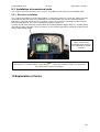
1
LX Navigation d.o.o.
LX Zeus
September 11th 2012
LX Zeus
LX Zeus 4.3
Users manual
(Preliminary)
LX Navigation d.o.o.
www.lxnavigation.si
Tel: 00386 3 4904670
Fax:00386 3 4904670
-1-
LX Navigation d.o.o.
1
LX Zeus
September 11th 2012
SYSTEM DESCRIPTION ............................................................................................................. - 5 -
1.1
Hardware concept .................................................................................................................. - 5 1.1.1 Rotary switches and push buttons ....................................................................................... - 6 1.1.2 USB and SD port.................................................................................................................. - 6 1.1.3 Connections ......................................................................................................................... - 6 1.2
Software .................................................................................................................................. - 7 -
1.3
Technical data......................................................................................................................... - 7 -
2
OPERATION AND CONTROLS .................................................................................................. - 8 -
2.1
System push buttons (5)........................................................................................................ - 8 -
2.2
Navigation push buttons (3) .................................................................................................. - 9 -
2.3
Custom creation of bottom rows ........................................................................................ - 10 2.3.1 Bottom row layout .............................................................................................................. - 10 2.3.2 Creation of first navigation sub page ................................................................................. - 10 2.4
Rotary switches .................................................................................................................... - 11 2.4.1 Rotary switches .................................................................................................................. - 11 2.4.1.1
Zoom Rotary switch................................................................................................... - 11 2.4.1.2
Audio volume rotary switch ....................................................................................... - 12 2.5
3
Automatic jump out of edit .................................................................................................. - 12 SETUP ........................................................................................................................................ - 13 -
3.1
Pilot specific settings........................................................................................................... - 13 3.1.1 Pilots................................................................................................................................... - 13 3.1.2 Audio settings..................................................................................................................... - 14 3.1.3 Voice .................................................................................................................................. - 14 3.1.4 Vario settings ..................................................................................................................... - 15 3.1.5 Indicators............................................................................................................................ - 18 3.1.6 Flarm settings..................................................................................................................... - 19 3.1.7 Flight recorder setting ........................................................................................................ - 19 3.1.8 Airspace management ....................................................................................................... - 20 3.1.9 Graphics ............................................................................................................................. - 20 3.1.9.1
Map palette................................................................................................................ - 20 3.1.9.2
Task colour palette .................................................................................................... - 20 3.1.9.3
Airspaces ................................................................................................................... - 21 3.1.9.4
Show TP till Zoom ..................................................................................................... - 21 3.1.9.5
Show Flarm till Zoom................................................................................................. - 21 3.1.9.6
Draw tail..................................................................................................................... - 21 3.2
System Setup........................................................................................................................ - 22 3.2.1 Units ................................................................................................................................... - 22 3.2.2 Turn points ......................................................................................................................... - 22 3.2.3 Glider (glider polar selection) ............................................................................................. - 22 3.2.4 Firmware update ................................................................................................................ - 23 3.2.5 Data transfer ...................................................................................................................... - 23 3.2.5.1
How to delete files ..................................................................................................... - 24 3.2.6 Service ............................................................................................................................... - 24 3.2.7 Layouts............................................................................................................................... - 24 3.2.7.1
How to provide customization ................................................................................... - 24 4
NAVIGATION MODES ............................................................................................................... - 27 -2-
LX Navigation d.o.o.
4.1
LX Zeus
September 11th 2012
APT mode (navigation to airports) ..................................................................................... - 27 -
4.2
How to select an airport? .................................................................................................... - 27 4.2.1 APT selection from NEAR function .................................................................................... - 28 4.3
Navigation in APT mode ...................................................................................................... - 28 4.3.1 Main graphic navigation page ............................................................................................ - 28 4.3.2 Second navigation page..................................................................................................... - 29 4.3.3 Third navigation page......................................................................................................... - 29 4.3.4 Map orientation .................................................................................................................. - 29 4.4
Appearance of Flarm objects .............................................................................................. - 29 -
4.5
Turn point mode ................................................................................................................... - 30 4.5.1 Selection of a Turn Point.................................................................................................... - 30 4.5.1.1
Selection from Near................................................................................................... - 30 4.5.2 Navigation to a Turn Point.................................................................................................. - 30 4.6
Task Mode ............................................................................................................................. - 31 4.6.1 Task organisation............................................................................................................... - 31 4.6.2 Task selection .................................................................................................................... - 31 4.6.3 Task creation by “hand” ..................................................................................................... - 32 4.6.3.1
Creation of Zones ...................................................................................................... - 32 4.6.4 Task Start, Restart and Next TP ........................................................................................ - 33 4.6.4.1
Task Restart function................................................................................................. - 33 4.6.4.2
Over Turn point.......................................................................................................... - 33 4.6.5 MOVE Function (during flight)............................................................................................ - 34 5
GPS SIGNAL MANAGEMENT .................................................................................................. - 35 -
5.1
GPS signal for navigation.................................................................................................... - 35 -
5.2
Colibri II Zeus interaction .................................................................................................... - 35 -
5.3
LX Zeus and Flarm ............................................................................................................... - 36 5.3.1 Visualisation of Flarm objects ............................................................................................ - 36 5.3.2 Flarm external displays ...................................................................................................... - 36 6
6.1
7
REMOTE CONTROL.................................................................................................................. - 37 Remote in second seat ........................................................................................................ - 37 SECOND SEAT UNIT ................................................................................................................ - 37 -
7.1
Connection of Vario and Remote........................................................................................ - 37 7.1.1 Secondary Vario setup....................................................................................................... - 37 7.2
8
Interaction LX Zeus – LX Zeus Second seat...................................................................... - 38 FLYING WITH LX ZEUS ............................................................................................................ - 38 -
8.1
Flight preparation on ground .............................................................................................. - 38 8.1.1 Before take off.................................................................................................................... - 38 9
INSTALLATION.......................................................................................................................... - 38 -
9.1
Mechanical installation ........................................................................................................ - 38 9.1.1 Installation of Vario unit...................................................................................................... - 38 9.2
Electrical installation............................................................................................................ - 39 -3-
LX Navigation d.o.o.
9.2.1
LX Zeus
September 11th 2012
Installation of USB D 60 (vario unit) ................................................................................... - 39 -
9.3
Installation of second seat units......................................................................................... - 40 9.3.1 Electrical installation........................................................................................................... - 40 10
EXPLANATION OF TERMS ...................................................................................................... - 40 -
-4-
LX Navigation d.o.o.
LX Zeus
September 11th 2012
1 System description
The system consists of minimum two units one of them is gliding computer and another unit is a 57 mm
vario unit. Gliding computer has a sunshine readable 5.5 inch colour display and a high power Linux
running computing device. Vario unit is a stand alone unit which electronics is based on high precision
digital sensor transducers. Connection between vario and computer unit is via LX system bus. System
extensions (second seat unit, remote control, compass ….) are also possible after using of LX system
bus solution. All connections are plug and play that means no exacting works which needs specialists.
The manual for LX Zeus and for LX Zeus 4.3 is the same as the units uses the same software.
Hardware is also nearly the same.
LX Zeus 4.3 highlights:
-layout: 82x103 mm
-graphic colour display (400x800 pixels)
-the same operation philosophy as LX Zeus
Note!
Pictures used in this manual may slightly
differ from the LX Zeus original screens.
1.1 Hardware concept
The system is designed to offer flexible solutions of system configurations, so the pilot is able to provide
some kind of custom design. At the back side of the unit there are plenty of connectors which makes
possible to connect (plug and play) a bright palette of GPS signal sources, as the unit doesn’t have
integral GPS receiver. Units as Colibri, LX 20, VL and any other GPS source which is capable to deliver
NMEA at nearly any baud rate, are compatible.
A special plug is provided for Colibri II connection in that case is Colibri II also powered from Zeus.
Using of Colibri II offers some important benefis for the pilot. The benefits are as follows:
-automatic switch on of Colibri II as Zeus becomes power
-automatic power off after Zeus will be switched off and the system isn’t in flying mode, if flight
status is detected Colibri II will go on with its own battrey
When two GPS sources are connected at the same time, both signals are combined and loosing of one
GPS source will not degrade system availability.
Colibri II is used as an IGC flight recorder in case of an IGC approved solution. In that case a high level
communication is established between Colibri II and Zeus and the pilot is able to operate the system,
the same way as by integral Flight recorder.
The unit can operate in portrait and also in landscape orientation. Conversion from portrait and vice
versa is simple and could be done by pilot.
-5-
LX Navigation d.o.o.
LX Zeus
September 11th 2012
Commercially avail abele versions:
-LX Zeus IGC: package consists of LX Zeus Computer, Colibri II flight recorder and USB D 60 vario unit
-LX Zeus Flarm: LX Zeus computer with Flarm unit and USB D 60 (IGC Flarm optionally)
-LX Zeus Flarm IGC: Zeus Computer, Flarm Colibri II and USB D
-LX Zeus: Zeus Computer and USB 60
1.1.1 Rotary switches and push buttons
There are 8 push buttons and two rotary switches
provided on the front of the unit. Every rotary switch
has also a push function. On one side there are
five push buttons which are all double occupied and on
another side there are three push buttons.
Short and long press can be used for direct access.
Buttons are labeled and this makes unit
manipulation very easy.
Both rotary switches are multifunctional as follows:
Default functions:
- audio volume adjustment function
- zoom selector
In edit:
-zoom: scrolling and confirmation after push
-volume: bigger steps of scrolling and escape/cancel
1.1.2 USB and SD port
An A size USB port is situated on the front panel.
The port is exclusively used for data transfer and firmware updates.
The firmware updates could be easily done also by customer.
SD port is active only in case of Flarm option. This ensures direct
communication with Flarm which means downloading
of flights, uploading of declaration and also Flarm update.
1.1.3 Connections
At the back side of the unit there are following connectors:
-4x 485 system bus*
-2x CAN bus**
-Colibri II port (5V and data)***
-Flarm port ( 12 V power and data)****
-2x Flarm display outputs
-1x Flarm SD
* 485 connects LX Zeus to:
-USB D 60 Vario unit
-Remote control stick
-secondary vario indicators
-compass
** CAN bus:
- connects Second seat unit
*** Colibri II port:
-makes possible to arrange direct connection
of LX Zeus to Colibri II only via cable (special cable necessary)
**** Flarm port can be also used to connect any GPS source which has an IGC standard connector
-6-
LX Navigation d.o.o.
LX Zeus
September 11th 2012
For instance: Colibri LX 20, VL……. If flarm is connected two Flarm display can be connected to the
system after using of Displ1 and Displ 2 plugs. SD plug connects SD card slot which is on the front
panel with Flarm.
1.2 Software
SW package is developed by LX Navigation and is running under Linux operation system. The SW
remained well known LX Navigation philosophy, but some new approaches have been involved. The
SW is continuously developed and upgrades are regularly published. Upgrades of SW can be easily
done by user without any passwords.
1.3 Technical data
Computer module:
-5,5 inch sunshine readable anti glare display
-power requirements: typically 400 mA at 12 V ( may vary regarding to backlight intensity)
-layout: max 106x146 mm, installation depth 52 mm, without Flarm
-8 push buttons
-2 rotary switches with push function
-USB size A port
Vario Module (USB D 60):
-57 mm air norm (60x60 mm)
-mechanical needle with colour display
-power consumption: 120 mA at 12 V
-485 bus compatible unit
-7-
LX Navigation d.o.o.
LX Zeus
September 11th 2012
2 Operation and controls
8 push buttons and two rotary switches are used as unit controls. LX Navigation Remote stick can be
also used to control the unit.
8 push buttons are divided into two groups. Group of 5 buttons situated near rotary switches are meant
for system inputs. All five buttons support two functions; all depends on press, if long or short. Short
press activate above labeled function and long press (apr. 2 seconds) activates secondary function.
Next 3 push buttons are used during navigation to switch between navigation modes. Those 3 push
buttons don’t support long press.
2.1 System push buttons (5)
st
1 button (VARIO/FLARM)
-VARIO (short press): input of MC, Ballast and bugs
-FLARM (long press): activation of Flarm radar screen
nd
2 button (TSK/MOVE)
-TSK . task management, for next actions use push
buttons near to the labels
-MOVE : executing of move function by AAT
rd
3 button (STAT/EVENT)
-STATISTICS: flight and task statistics
-EVENT: activation of Event function in Colibri II
th
4 button (SELECT/NEAR)
-SELECT: selection of APT, TP and TSK
-NEAR : activation of near function (Airport…)
th
5 button (SETUP/INFO)
-SETUP: direct access to Setup menu
-INFO. information about system configuration
-8-
LX Navigation d.o.o.
LX Zeus
September 11th 2012
2.2 Navigation push buttons (3)
Three buttons are used to leaf through navigation
menus of LX Zeus.
st
1 button (A
P
T)
APT: after each press next mode will be selected
(APT, Turn Point, Task)
nd
2 button SUBP
SUBP (sub page) : after every push next page of
APT, TP or TSK menu will open.
The procedure is circular
Main page
st
* 1 sub page is full numeric page which consists
Nav boxes. All nav boxes are custom configurable.
1st subp.*
** 3 d terrain page
2nd subp**
rd
3 button (1- 4)
1-4 : LX Zeus uses bottom row for nav boxes presentation. Up to
4 variants are fully custom programmable and selectable by
1-4 push button.
Actual bottom row variant
Is shown by a number
(1-4) which position is in the right
lover corner.
-9-
LX Navigation d.o.o.
LX Zeus
September 11th 2012
2.3 Custom creation of bottom rows
Any position can be custom designed.
The procedure starts after a long press on Zoom button.
A yellow marked window shows ready status.
Rotate Zoom to find position of interest and
Press Zoom. A list of possible nav box information
will open, select with Zoom and confirm by press.
Note!
To select next bottom row which is
still empty simple position yellow
window to the last position (full
right) and press on 1-4 button.
Note!
Edit of bottom row is also possible
during flight.
2.3.1 Bottom row layout
Bottom row can be positioned on the bottom of the display
and as well on the top. By portrait the pilot can also choose
one row or two rows variant. One row variant saves
a lot of space for graphic. The conversion may be done
after update of .lyt file, after using of Transfer item of Setup.
480x 640 designator defines portrait and 640 x 480
landscape orientations.
.lyt files are included in every firmware update package.
The files should be copied to the USB stick.
Examples of bottom row layouts
Note!
Layout update couldn’t change display orientation from portrait to landscape and vice versa. At the
moment this should be done in the factory.
2.3.2 Creation of first navigation sub page
Use the dame method as by bottom row creation.
- 10 -
LX Navigation d.o.o.
LX Zeus
September 11th 2012
2.4 Rotary switches
Two rotary switches with push button functions
2.4.1 Rotary switches
Both rotary switches are multifunctional, so after their basic functions which are audio volume
adjustment and zoom adjustment. Both switches offer also some significant functions connected to edit
and selection.
2.4.1.1 Zoom Rotary switch
Its direct function is selection of zoom factor (scale of the map)
in graphic page. After every change a new scale factor will
be selected, actual scale is shown as 1: xxxxxx and not in
kilometers resp. Nm.
2.4.1.1.1 Additionally functions of Zoom
After press has been activated the function of Zoom rotary
switch will change and the switch will become most common
used switch for LX Zeus operation during edit and selection processes.
Any input and also scrolling can be done after using of Zoom switch.
Note!
Push on Zoom should be used after any attempt to
make inputs. After press immediate inputs are
possible when rotating the knob.
Example 1: update of MC
1.
2.
3.
4.
press Vario button
select item (MC, Bal..) by Zoom knob (rotate)
press on Zoom knob
adjust new value, rotating Zoom
Example 2: selection of an airport
1. press Select button (short press)
2. press button near APT icon (Stat)
3. selection menu will open
4. now use Zoom knob to select item of interest, you can enable filtering by Countries and also
by Name.
5. highlight airport of interest and close the procedure with press on Audio Volume button
- 11 -
LX Navigation d.o.o.
LX Zeus
September 11th 2012
2.4.1.2 Audio volume rotary switch
a bar will show audio volume status after rotation.
2.4.1.2.1 Additionally functions
The main secondary function of Volume rotary switch is its
press function. When pressed in edit mode will execute jump out
of the menu. The push function isn’t active in navigation
menus (APT, TP and TSK). After activation all already done edit inputs will remain, so the button isn’t a
cancel button.
During scrolling where Zoom rotary switch makes one step, using of Volume will increase steps by
factor 5.
During input of numbers and letters, rotating will delete wrong input character and move cursor one
position back.
2.5 Automatic jump out of edit
If you get lost in edit simple don’t touch any command for apr. 8 seconds and the unit will change back
to the last selected menu,
- 12 -
LX Navigation d.o.o.
LX Zeus
September 11th 2012
3 Setup
Setup menu is available after short press on SETUP labelled push button. The menu is divided into two
sections. System settings are settings which are valid for the whole system and couldn’t be pilot
specific data. Items connected to pilot may vary from pilot to pilot and depend on pilot individual
requirements. Suitable symbols will accompanied with text will help you to find the menu of interest.
-use Zoom to find out menu of interest (selected menu size will increase)
-use push function of Zoom to enter menu
3.1 Pilot specific settings
3.1.1 Pilots
Pilots name and some personal data can be stored.
All stored pilot names will be offered during booting
and selection of one pilot is mandatory.
- 13 -
LX Navigation d.o.o.
LX Zeus
September 11th 2012
3.1.2 Audio settings
This menu defines audio configuratiuion. Audio
generator is a part of Vario unit (USB D 60) but
commands are stored in LX Zeus. General audio
part speaks about audio of variomter and SC.
Speed command mode:
-defines audio in SC, there are several variants
Speed command volume:
-defines audio volume in SC, may be increased
decreased……
Vario tone:
-defines audio in vario mode, you can adjust
frequencies and also types of audio, use test
vario after adjustment
Alarm:
Vario unit is also capable to generate some
alarms (warnings), combining two frequencies.
Set frequencies and time intervals and use Test
to check.
3.1.3 Voice
In case that LX Voice Module is a part
of the system following settings can be arranged.
Volume:
- Voice volume: defines volume of expressed
messages
-Vario mixer: defined volume proportion Audio/Voice
LX Specific:
-enables or disables Zeus warning info
Flarm:
-enabling and disabling of Flarm info and
warnings
- 14 -
LX Navigation d.o.o.
LX Zeus
September 11th 2012
3.1.4 Vario settings
Settings of this menu defines vario characteristics
and some other important inputs connected to
vario and speed command.
Vario:
-vario filter defines dynamic of vario needle
lover number means faster reaction and vice versa
-smart vario*
-vario average time (display on vario unit)
-vario scale, three options (2.5, 5 and 10 m/s)
(5, 10 and 20 kts)
Other:
-Silence range, defines no audio area by
speed command, set needle deflection
-SC switching threshold, changeover speed
which will change from vario to SC in case of
Auto setting
-ETA (Estimate Time of Arrival) calculation, you can
choose between several options
-Automatic SC switching, defines way of automatic
change over to SC
-External switch mode**, determinates external SC
switch status which change over to SC
TE value***, set TE compensation style, 0%
for tube compensation
TE filter*** only valid by electronic TE compensation
*
The LX system incorporates two configurable electronic filters in the circuitry. The first filter adjusts
the time constant and is adjustable between 0.5 and 5 seconds. The 0.5 setting is the fastest while the
5 setting provides maximum damping.
The second filter, called the Smart Vario, is a dynamic filter and controls the rate at which the vario
indication moves. When set to OFF, there is no restriction on the rate of movement of the vario
indication other than the setting of the time constant filter. When set to 1, the vario indication will not
move faster than 1 m/s (2 kts) per second, while when set to 4, the vario indication will not move faster
than 4 m/s (8kts) per second. It should be noted that when set to 4, the vario indication will move four
times faster than when set to 1.
Summary:
The Smart Vario should not be used in isolation but in conjunction with the setting of the time
constant filter. When the Smart Vario is activated, the time constant filter may need further
adjustment to provide optimum indications.
RAW VARIO
FILTERED
VARIO
FILTER
0.5 to 5
SmartVario
FILTER
1 to 4 or OFF
VARIO
INDICATION
- 15 -
LX Navigation d.o.o.
LX Zeus
September 11th 2012
**
LX Zeus unit has a connection for an external speed command switch, which is wired to vario unit.
Using an external switch it is possible to switch between SC and Vario manually. Setting the SC Switch
to ON means that closing of the switch will cause SC mode, and setting SC INPUT to OFF means that
closing the switch will select Vario mode. There is a third option by setting SC INPUT to Toggle and
connecting a push button each press will toggle between SC and Vario (obligatory setting when using
the LX Remote).
Wire
SC, Marked
cable
Schield
Wire
Wire
Wire
Wire
Open
Closed
Closed
Open
Shield
Shield
Shield
Shield
Setting: ON
Setting: OFF
Setting: ON
Setting: OFF
Staus: VAR
Staus: SC
Staus: SC
Staus: VAR
Wire
SC, Marked
cable
Shield
***
LX Zeus has the capability to offer variometer total energy compensation in two
ways. Selection of compensation method is done after selection the % figure.
000% means total energy compensation when using a TE tube. When using this
solution the unit does not process compensation this depends entirely
on the TE tube and its installation. After an input of a percentage which is other than
zero the special software routines will be activated and will provide an electronic
compensation process. The default value is 100% but this can be varied following
a test flight.
Note!
Electronic and pneumatic TE compensation requires
different connection of tubes.
The TE compensation can be fine tuned during flight with the following procedure. It is essential that
this is only done in smooth air; it is not possible to tune the TE accurately when it is thermic.
•
•
•
Select 100 % and default TEF
Accelerate up to approximately 160 km/h (75 kts) and keep the speed stable for a few seconds
Gently reduce the speed to 80 km/h (45 kts)
Observe the vario indicator during the manoeuvre. At 160 km/h (75 Knots) the vario will indicate about –
2 m/s
(-4kts). During the speed reduction the vario should move towards zero and should never exceed zero
(slightly positive indications are acceptable). If the vario shows a climb, then the compensation is too
low, increase the TE%; and vice versa. Repeat this procedure and make further adjustments if
necessary.
- 16 -
LX Navigation d.o.o.
LX Zeus
September 11th 2012
The TEF (TE filter) is the compensation delay. Larger numbers will increase the delay and vice versa.
During the first test is recommended to use TEF 4.
Electronic TE is only effective when the pitot and static sources are co-located and the pneumatic lines
to the instrument are approximately the same length. The best sensor to use is the combined pitot/static
Prandtl tube. If problems are experienced with the electronic TE compensation, then the most likely
cause is the glider's static source. The static source can be checked by plumbing the pneumatic tubes
for electronic compensation and then setting the TE: to 0%. In still air, accelerate to approximately 160
km/h (75 Knots) and reduce the speed. Observe the vario indicator. If the static source is good, then the
vario should immediately start to move to show a climb. If the needle initially shows increased sink and
then moves to a climb, the static source of the glider is unsuitable and there is no way to provide
successful TE compensation electronically. The use of a dedicated and accurate fin mounted pitot/static
source such as a Prandtl tube might help.
There are two ways by which the vario units can be corrected for total energy; electronic TE
compensation based on speed changes with time; and pneumatic compensation with a TE probe. When
using pneumatic compensation by use of a TE probe. The quality of the TE compensation depends
entirely on the location, size and dimension of the TE tube. The installation must be leak-proof.
Note!
If electronic TE compensation is selected, then the TE(Pst) port should be connected to a good static
pressure source. If pneumatic compensation is selected, then the TE(Pst) port should be connected to
the TE probe.
TE(Pst)
LX 7007
Compensation with TE probe
Electronic compensation
- 17 -
LX Navigation d.o.o.
LX Zeus
September 11th 2012
3.1.5 Indicators
LCD indicator means vario indicator with it’s mechanical
needle and colour graphic display.
The system is capable to drive also secondary indicators.
Secondary indicators may be simple repeaters or may also indicate
different data sets, it all depends on the indicator number setting.
Vario unit is always addressed as Number 1, secondary indicators
can be addressed from 1 up to four.
Note!
Every setting should be set twice once for vario mode and
once for SC mode.
SC* dot ind.
Upper dig. indcator
Needle
Lower dig. indicator
Needle status indicator
•
A radial moving dot serves as a continuous speed to fly indicator, no setting is possible.
Some explanations of terms:
Vario needle : xxxxx, means needle function in vario mode, eg; vario, SC, Netto….
SC needle: xxxxxx, means needle function in SC mode
Vario up nr.: upper numerical display indication in vario mode
SC low nr.: lower numerical display in SC mode
- 18 -
LX Navigation d.o.o.
LX Zeus
September 11th 2012
Secondary indicators
Secondary indicators should be connected via 485 system bus.
There are three 9P connectors at the back of the unit
All contacts are absolutely parallel, so it doesn’t matter which one
is occupied. The unit can be also used as 485 system bus
splitter. To define Ind number use DIP switches which you find at
the back of the unit.
Note!
Units having Adr1
will simply repeat
what is displayed
on the vario.
Higher addresses
makes possible
different sets.
Number
Switch
IND 1
IND 2
IND 3
IND 4
x x
x
x
x
x
x x
Note!
Indicators which operate in
second seat, should be
connected to second sat 485 bus
After indicator functions have been defined, switch the unit off and then on again, this procedure will
memorize the settings.
3.1.6 Flarm settings
Flarm parameters of pilot interest can be
input via that menu.
3.1.7 Flight recorder setting
Not active at the moment.
- 19 -
LX Navigation d.o.o.
LX Zeus
September 11th 2012
3.1.8 Airspace management
All settings connected to AS management are available in this menu.
Note!
This menu makes possible to
set map orientation. This can be
North up and Track up and a
combination of track up and north
up, respectively to climbing and
straight away flight.
Show on zoom, defines appearance of
particular airspace sections on the display.
Appearance is connected to zoom.
AS warning can be set as active or as
not active (⌧).
3.1.9 Graphics
Makes possible to adapt pallets of colours
for different items.
3.1.9.1 Map palette
To adapt map colours regarding to pilot
personal requirements use this menu.
There are six variants offered.
3.1.9.2 Task colour palette
All possible colour sets can be preset for
task start, task legs and the finish line.
The same is also with sectors their
outlines and fills.
- 20 -
LX Navigation d.o.o.
LX Zeus
September 11th 2012
3.1.9.3 Airspaces
You can define colours of airspace sections
which will fulfill your individual requirements.
3.1.9.4 Show TP till Zoom
This setting defines appearance of turn points
in the graphic page.
3.1.9.5 Show Flarm till Zoom
Flarm object appearance can be adjusted.
3.1.9.6 Draw tail
Track of last flown minutes can be defined
with this setting.
- 21 -
LX Navigation d.o.o.
LX Zeus
September 11th 2012
3.2 System Setup
The parameters set in this section are valid for all pilots and are therefore global.
3.2.1 Units
A huge palette of units can be defined
in this menu.
3.2.2 Turn points
3.2.3 Glider (glider polar selection)
There are nearly all glider poplars stored in the
LX Zeus memory. Additionally to those polars
Is also possible to use so called user polars
After input of polar parameters.
- 22 -
LX Navigation d.o.o.
LX Zeus
September 11th 2012
3.2.4 Firmware update
Zeus firmware upgrade is executable by
USB stick. The actual files should be copied
to the stick directly to the root, no folders
are allowed. The procedure is easy and
safe, so there are no limitations not to be
provided by customers. A detailed manual
informs about the procedure. The same stick
which is used for data exchange is also suitable
for firmware update.
Every release is equipped with detailed instructions
and files. Upgrade data is available on
http://www.lxnavigation.si/avionics/avionics/downloads/zeus_update/Zeus_update.zip
3.2.5 Data transfer
The only solution to transfer data to LX Zeus
and vice versa is via USB stick. One stick is
also part of delivery. Different to firmware solution
the stick should contain one LX Folder with
subfolders (APT, TP, AS,…). The stick which
comes with the unit is already prepared.
After enter on item of interest (press on Zoom)
the procedure will start.
Note!
All files except airport file (.af) require
activation. After activation the data will become
active, means useable for navigation*. Up to
three turn point files can be active at the same
time. Unlimited number of TP and AS files can be
stored in Zeus memory
*Turn points of all three files will be selectable
without any limitations and ready for navigation.
File specification:
-airports
.af (LX Navigation format)
-turn points
.cup
-airspace
.cub
- 23 -
LX Navigation d.o.o.
LX Zeus
September 11th 2012
3.2.5.1 How to delete files
If there are some files stored in LX Zeus memory which
are not any more actual, those files can be removed when
using Delete internal files command. The command is
executable for Airports, Turn points and Airspace.
3.2.6 Service
This menu is foreseen for maintenance
and some system adjustments.
The only item for pilot is Local time
adjustment.
3.2.7 Layouts
The display orientation can be adjusted only in the factory to landscape or portrait, but the pilot has a
huge freedom to adjust the display under his individual requirements.
The display information consists of:
-map
-indicators as: speed and vario bars, wind indicator
final glide box, thermal assistant, altitude profile
-mode and status row
-bottom nav box row
-elevation profile
Each of listed
information cells can be
custom adjusted by the pilot.
Following is possible:
-size adjustment
-position movement
-enabling and disabling of individual
cells.
3.2.7.1 How to provide customization
Call setup menu and select layout option.
Press zoom to start.
A very typical screen will appear:
- 24 -
LX Navigation d.o.o.
LX Zeus
September 11th 2012
Edit of layouts may be synchronized for all three navigation
pages, or can be done for each page separately.
Check items of interest and start the procedure with Edit command.
Rotation of zoom will select information cells, selected cells will
get a coloured frame.
3.2.7.1.1 Move and resize of cells
After cell selection the customisation can start.
Press zoom and screen with up/down and
left/right movement symbol will appear.
Use zoom and volume knobs to move the cell. Next press
on zoom will make possible to resize the cell.
- 25 -
LX Navigation d.o.o.
LX Zeus
September 11th 2012
Example of moved an increased final glide box.
3.2.7.1.2 Customisation of cells
After a long press (zoom) on any cell the customisation
can follow.
Actions can select or deselect display cells.
Important!
Restore to default command will restore
to factory preset variant.
Customisation of bottom row
Customisation of bottom row includes also
Commands to define one, two or three bottom
rows.
Example of two bottom rows
- 26 -
LX Navigation d.o.o.
LX Zeus
September 11th 2012
4 Navigation modes
LX Zeus offers three navigation modes for navigation. The modes are:
-APT: navigation to Airports which are stored in APT memory
-TP : navigation to turn points (TP)
-TSK: task navigation after a task has been started
Any of three modes is selectable after sequenced pressing on A-P-T push button.
4.1 APT mode (navigation to airports)
LX Zeus is capable to store more airport data files
in .af format (LX Navigation airport format).
At the same time only one file can be active.
Selection of file should be carried out in
Setup/Transfer section Airfields.
APT mode consists from three navigation pages.
See also 2.2.
Any of them is selectable by SUBP button.
4.2 How to select an airport?
Airport selection is active from the main
graphic page and also from sub pages. Use
Select button (short press) and select menu will open.
Use APT option and selection dialogue will start.
Now you can scroll with Zoom knob or you can use
County and Name filters to reduce number of offered
airports. After airport of interest is found terminate the
process with short press on Zoom.
Note!
When using Name filter, input the first letters of the
airport name. Use Zoom to scroll and press for
confirmation. You don’t need to input all characters
just first two or three and after you can go on by
pressing Zoom. More inputs makes offer more
detailed and vice versa.
- 27 -
LX Navigation d.o.o.
LX Zeus
September 11th 2012
4.2.1 APT selection from NEAR function
LX Zeus offers also so called NEAR function.
After activation which can be done by a long
press on SELECT/NEAR button nearest Landable
points will be offered. The list includes airports from
airport data base and also turn points declared as
landable.
Note!
Selection is limited to 200
nearest points
4.3 Navigation in APT mode
There are three navigation pages possible all selectable by SUBP button.
4.3.1 Main graphic navigation page
Distance
Status indicators
Steering com.
APT name
Variometer bar
IAS bar
Course line
Final glide indicator
The bottom row consists of nav boxes, there are four bottom row variants available that means
maximal 24 nav boxes can be used. Bottom row variants are selectable by 1-4 push button. Any nav
box content is custom programmable after using of a very simple procedure. How to create nav box
structure see 2.3
Note!
The number of nav boxes depends on layout variant.
- 28 -
LX Navigation d.o.o.
LX Zeus
September 11th 2012
4.3.2 Second navigation page
This is a page without graphic display, the whole
display area can be filled up with nav boxes.
The method how to place individual nav box has
been described in 4.1.1.2.
4.3.3 Third navigation page
The third navigation page shows terrain
data in 3D configuration
4.3.4 Map orientation
LX Zeus can work in different map orientation modes as follows:
-track up
-north up
-combination of north up and track up
Use Setup/Airspace to select appreciate solution.
4.4 Appearance of Flarm objects
If Flarm is connected to LX Zeus Flarm
objects may be shown on graphic display.
Its appearance depends on setting done in Graphics.
This setting is global and valid for all three navigation
pages.
- 29 -
LX Navigation d.o.o.
LX Zeus
September 11th 2012
4.5 Turn point mode
The structure of the mode is similar to APT, the only important difference is, that the navigation is
towards turn points which are included in turn point files. The turn point files (.cup) should be uploaded
by USB stick. See Setup Transfer for details.
Note!
Up to three turn point files can be active at the
same time. The activation should be provided in
Setup/Transfer. Turn points included in all three
files will be available for navigation, without any
priority.
Turn point mode has also three pages, which can
Be selected by SUBP key.
4.5.1 Selection of a Turn Point
The selection process is similar to APT. Use SELECT
button to start the process and press TP. Name
and Country filter will expedite selection. Turn points are
visualized by a
symbol.
W
Important!
Turn points without country designator are selectable
only when using Country “All” option.
4.5.1.1 Selection from Near
LX Zeus Near function offers Turn point selection based on distance.
Respect that there is also Country filter active, use All if you want
to get all turn points listed.
4.5.2 Navigation to a Turn Point
Navigation towards turn point doesn’t differ to navigation to an airport, so refer 4.3 for details.
- 30 -
LX Navigation d.o.o.
LX Zeus
September 11th 2012
4.6 Task Mode
Task is a complex process which guides the pilot around the turn points of the task. The task consists of
turn points, start point and the finish point. Additionally take off and landing can be input, but those
points don’t have any influence on task execution.
4.6.1 Task organisation
Zeus has a store for 101 tasks. 50 tasks can be
imported in one .cup file and such tasks are called
imported (IMP), next 50 can be created by user in
LX Zeus (by hand) and those tasks are called User (USR).
One task is called DECLARED. This task hasn’t any
priority, the only specialty is that DECL task will be
automatically transferred to Colibri II and will be stored
there as a declared task. That means the task
will be regularly declared in flight recorder.
Any IMP and also USR task can be converted
Into Declared after execution of Declare command.
DECL task can be also edit by hand. To upload task use
Transfer menu.
1x
DECLARED
USER
50 x
IMPORTED
50x
USER
Note!
Tasks which you want to upload to Zeus
should be copied to TP subfolder of LX
folder.
Note!
LX Zeus task store has practically unlimited
capacity. At the same time only three .cup files
can be active. Use select 1, 2 and 3 option.
4.6.2 Task selection
To select task from LX Zeus active task store
use select button and go on with TSK option. Use
Zoom knob to select task of interest. During selection
process all task relevant data will be present.
- 31 -
LX Navigation d.o.o.
LX Zeus
September 11th 2012
4.6.3 Task creation by “hand”
The task can be created by hand after using of NEW
or EDIT command, both commands are available
after press on TSK button. Edit will make possible to
edit an existing task and new will offer creation of
a new task, which will be stored under USER.
Insert turn points one by one.
Selection of take of and landing, with limited options
Selection of turn points offer more options.
Option Zone makes possible to adapt zone geometry
to actual rules.
Note!
Selection of turn points and airports
correspond to procedures described in
4.2 and 4.4
4.6.3.1 Creation of Zones
ZONE function makes possible to create any
known geometry for turn points, start and finish.
The creation consists of input of sector angles
radius and orientation.
Auto next input defines change over philosophy
over turn point. AUTO means automatic change
over immediatelly after sector will be reached.
This function is default active as sector radius
is below 10 km. Bigger sectors offer a not automatic
change over. If auto next no is active, MOVE function
will become active and that makes possible
to modify the task distance even before flight.
Exsamples of typical zone geometries.
- 32 -
LX Navigation d.o.o.
LX Zeus
September 11th 2012
4.6.4 Task Start, Restart and Next TP
Thre are two methodes of staring a task. Manual
start is posible after using of Next TP function. Next TP
command will change over to next TP every time when
activated, doesn’t matter if the glider is in the sector
or not.
A more sophistic start method is automatic solution.
In that case the pilot should ARM automatic start.
Use ARM command which is offred after press on
TSK button. Activation of ARM and also deactivation
are clearly shown on the display. Disarmed means
canceleratin of ARM status.
4.6.4.1 Task Restart function
After task has been started (method doesn’t matter)
a task restart can be executed at any time.
Use Restart button of TSK menu.
Restart button will become active after task start.
After restart all task statistics data will be zeroed and
ARM status will become active, which makes
possible to provide next automatic start.
4.6.4.2 Over Turn point
Change over to next turn point may be automatic
or manual. Automatic change over will happen
when Auto next of individual zone is set to auto.
Default setting for Auto next:
-R1below 10 km Auto next active (automatic change over)
-R1 above 10 km manual change over necessary
Use menu Zone of particular turn point for adjustment.
- 33 -
LX Navigation d.o.o.
LX Zeus
September 11th 2012
4.6.5 MOVE Function (during flight)
When flying an AAT big sectors are set and therefore
the pilot has to decide where to turn to next point.
Function Move helps the pilot to find optimal solution.
After long pres on TSK / MOVE button so called
move function will become active.
Use Zoom and Vol knobs to move the turn point.
All task relevant data which are affected by move
are shown at the bottom part of the display.
Note!
Change over to next TP is the same as
described in 4.5.4. As turn point data is
taken actual position which is synchronized
with change over time.
- 34 -
LX Navigation d.o.o.
LX Zeus
September 11th 2012
5 GPS signal management
LX Zeus has two inputs for GPS signal which
are available on the back of the unit.
both solutions are realized by 6P telephone
type connectors which are marked as:
-Colibri II
-Flarm
Colibri II plug can be used exclusively to connect
Colibri II units. The plug delivers also power (5V)
to Colibri and receives its data directly without
Power data interface. The communication way
is bidirectional.
Flarm marked input makes possible to realize
a plug and play solution to connect any unit which has
an IGC standard compatible connector. Port delivers
also 12V.
Following units can be connected plug and play:
-Colibri, LX 2000 – 2000, VL, LX Flarm RB, LX Flarm MB, Flarm
5.1 GPS signal for navigation
Both GPS input connectors are wired to LX Zeus microcontroller module which prepares an integral
GPS signal for the main computer. So, the computer will be supplied with valid GPS signal as long as
one GPS receiver delivers valid data. Colibri II data have priority, to guaranty that navigation data will
match flight recorder data. A symbol which is positioned in the right upper corner of the display shows
GPS signal status:
-red GPS BAD
-yelow poor GPS, but valid
-green GPS OK
5.2 Colibri II Zeus interaction
Colibri II will switch ON automatically when power from Zeus will be applied. In case that Zeus will go off
during flight, Colibri will remain ON using its own internal battrey. In normal situation which means that
Zeus will be switched OFF on ground after landing, Colibri II will go OFF automatically after no flying
mode will be detected (this takes some minutes). Described philosophy prevents that Colibri will remain
on after landing by pilot mistake. The solution also makes possible to install Colibri II inside of the panel
or in baggage department.
- 35 -
LX Navigation d.o.o.
LX Zeus
September 11th 2012
5.3 LX Zeus and Flarm
Flarm should be connected to FLARM marked plug of LX Zeus. Flarm will also receive power via that
plug. If Flarm is also connected to aircraft power network via its power input wires, doesn’t happen as
there is a diode built in, which separates both power supplies. Up to two Flarm external displays can be
connected to the plugs marked as Falrm external display. SD card slot on LX Zeus front is directly
connected to Flarm SD interface (valid for RB ) and there is no influence of Zeus. The card may be
used for:
-Flarm firmware update
-downloading of flights stored in Flarm
-uploading of declaration
On the back side of LX Zeus there is enough space
to install LX RB as an integral part of the system.
All connections are plug_and_play.
Non integral solutions can also used.
5.3.1 Visualisation of Flarm objects
Flarm objects are visualised in two different ways.
First one becomes active after activation of so called
Flarm radar screen (long press on FLARM).
Flarm objects are also visible in all three graphic
navigation pages.
5.3.2 Flarm external displays
LX Zeus HW makes possible to connect
maximal 2 Flarm external displays, both
plugs are driven from Flarm directly without
any Zeus influence.
- 36 -
LX Navigation d.o.o.
LX Zeus
September 11th 2012
6 Remote control
LX Zeus can be also operated by remote
control stick. The stick is standard LX Navigation
product which differs from sticks used by
LX 7000/7007 series only in labelling.
Therefore is upgrade of existing stick very easy.
Remote stick should be connected to one
485 plug, no special initialization is necessary.
6.1 Remote in second seat
Remote stick for second seat is the same as for the first seat (no different firmware as by LX
7000/7007). The unit should be connected to second seat unit 485 bus.
7 Second seat unit
Second seat device is connected to the master
unit via CAN bus, the connection includes also
power for second seat. This means that second
seat unit doesn’t need power supply. An external
toggle switch makes possible to switch off the unit
during single pilot operation period. Otherwise
all commands are the same as by main unit.
GPS inputs are inoperative, so there is no sense
to connect GPS sources to that plugs, the same
is valid for Flarm display plugs.
LX Zeus 4.3 can be also used as a repeater in case
panel space problems.
7.1 Connection of Vario and Remote
Vario indicator (not USB D unit) should be
connected to 485 bus of second seat device
(this is not the same as by LX 700077007).
The same is valid for remote. Both vario
indicators and remotes are compatible with
existing units connected to LX 7000/7007.
Remote doesn’t require any setup.
7.1.1 Secondary Vario setup
Function of vario indicator connected to
second seat unit, should be defined in
Setup of second seat unit.
- 37 -
LX Navigation d.o.o.
LX Zeus
September 11th 2012
7.2 Interaction LX Zeus – LX Zeus Second seat
8 Flying with LX Zeus
It is recommended to prepare the unit for every flight before take off to ensure a stresses and
contentedly flight. This is especially important before any contest, record or badge flight.
8.1 Flight preparation on ground
It is suggested to check following:
-data base status
-prepare task (use new or edit options, or select from task store)
8.1.1 Before take off
-switch the unit ON at least 3 minutes before take off (this will ensure sufficient GPS reception and will
create a base line of baro trace)
-select correct pilot (many setting belongs to pilots)
-check task if correct after using of Task edit
-if declaration is obligatory, check if selected task is declared type
-switch on second seat unit in case of double seated glider
9 Installation
9.1 Mechanical installation
As the unit dimensions doesn’t match air norm standard, a new cut out in the panel should be made.
There are two ways how to prepare the panel. First one is buying of a new panel and second solution is
upgrade of existing panel. Upgrade can be done also by user; in that case some little experience in
glass fibber technology would help. Instructions how to rebuild the panel you can obtain by LX
Navigation. Every unit comes also with an iron template which makes possible to manufacture LX Zeus
cut out by hand. In case of CNC solution, please ask for .dwg file.
Reinstallation after panel upgrade
9.1.1 Installation of Vario unit
The unit occupies one 57 mm standard cut out. The maximal dimensions of the unit are 60x60 mm and
don’t exceed dimensions of classic pneumatic instruments. In case of space problems, the unit can be
separated into two parts which are connected via cable.
Note!
Respect labels near pneumatic connectors, during pneumatic tube connection process. See also
3.1.4 for details.
- 38 -
LX Navigation d.o.o.
LX Zeus
September 11th 2012
9.2 Electrical installation
This part of installation is easy and doesn’t need any specialists. The system receives its power via two
power lines which should be connected to 12V glider power source and ground. Red wire is 12V and
blue wire is Ground.
Important!
There is no fuse built in the system, obligatory use 3A external fuse. Never remove Terminator
which occupied one CAN port (factory preset). Terminator should be removed in case of second
seat configuration. In that case the terminator should be positioned on second seat unit.
A 2 pole plastic connector which is positioned approximately 20 cm from the unit casing ensures simple
disassembling of the unit in case of repair.
9.2.1 Installation of USB D 60 (vario unit)
USB D 60 unit comes with prefabricated cable set, which has two connectors. 15 pole type should be
inserted into vario unit and arrested with appropriate springs.
The 9P connector should be inserted into any free 485 marked plug on Zeus back. The unit receives
also its power from Zeus.
See 3.1.4 to learn how to connect SC external switch.
Speaker output is terminated with one chinch female connector; a male connector is part of speaker.
- 39 -
LX Navigation d.o.o.
LX Zeus
September 11th 2012
9.3 Installation of second seat units
The second seat unit is the same size as master, so no difference by mechanical installation works.
9.3.1 Electrical installation
The second set unit doesn’t need external power, as it becomes power via system bus (CAN). For CAN
connection two 8P connectors are provided on master and also on repeater. The interconnection of
both units is extremely simple and easy, all what is necessary is to insert CAN marked cable in one of
two CAN marked plugs. The same is valid for first and for second seat.
Second sat unit comes with two red wires which are terminated with a toggle switch. It is recommended
to install the switch somewhere in the rear panel, as this will make possible to switch off second sat unit
during single pilot operation.
Note!
Newer remove CAN
terminator which occupies
one CAN plug of second
seat unit.
Note!
All interfaces as; remote control, vario indicators…… which interact with second seat, should also
be connected to second seat 485 bus.
10 Explanation of terms
- 40 -