1
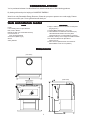
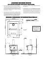
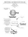
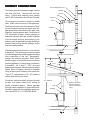
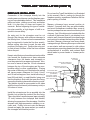
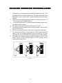
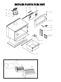
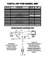
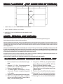
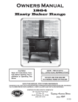
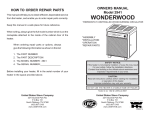
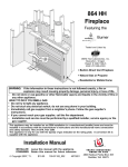
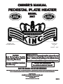
OWNER'S MANUAL
PEDESTAL PLATE HEATER
MODEL
2007
STATES STO
VE
ITED
N
U
USSC
COMPANY
STATES STO
VE
ITED
N
U
USSC
COMPANY
TESTED TO
UL 1482
&
CAN/ULC - S627
EXEMPT PER
EPA METHOD 28A
CAUTION!
Read All Instructions Carefully
Before Starting The Installation
or Operating This Heater.
SAFETY NOTICE:
If this heater is not properly installed, a house fire may
result. For your safety, follow the installation instructions. Contract local building or fire officials about
restrictions and installation requirements in your area.
Improper Installation Could Void
Your Warranty!
DO NOT USE THIS HEATER
IN A MOBILE HOME OR TRAILER
SAVE THIS MANUAL FOR FUTURE REFERENCE
THIS MANUAL WILL HELP YOU TO OBTAIN EFFICIENT, DEPENDABLE SERVICE FROM THE HEATER, AND ENABLE
YOU TO ORDER REPAIR PARTS CORRECTLY. KEEP IN A SAFE PLACE FOR FUTURE REFERENCE.
Distributed By:
UNITED STATES STOVE COMPANY
227 INDUSTRIAL PARK ROAD
P.O. BOX 151
SOUTH PITTSBURG, TN 37380
1
2720 B
CONGRA
TULA
TIONS!
CONGRATULA
TULATIONS!
You've purchased a heater from North America's oldest manufacturer of wood burning products.
By heating with wood you're helping to CONSERVE ENERGY!
Wood is our only Renewable Energy Resource. Please do your part to preserve our wood supply. Plant at
least one tree each year. Future generations will thank you.
tools and materials needed
MATERIALS
6" Pipe, 6" Elbow, Collar and Thimble; As Required
(24 gauge min.)
1/2" Sheet Metal Screws (No. 10A x 1/2")
6" Inside Diameter Underwriters Laboratories (UL)
Listed Residential Solid Fuel Factory-Built
Triplewall Chimney or Exiting Masonry Chimney.
In Canada, chimney must comply with CAN/ULC S629
Floor Protector Material As Specified in
Figures 2,3, &4.
Furnace Cement (Manufacturer Recommends:
Rutland Black Code 78 or Equivalent)
TOOLS
Pencil
6 Foot Folding Rule or Tape Measure
Drill, Hand or Electric
Drill Bit 1/8" Dia. (For Sheet Metal Screws)
5/16" Nut Driver or
5/16" Socket w/Ratchet
Screw Driver (Blade-Type)
Gloves
Safety Glasses
Dimensions
(TOP VIEW)
(SIDE VIEW)
(FRONT VIEW)
2
SAFETY RULES
SAFETY NOTICE: If this heater is not properly installed a house fire may result. For your safety, follow the
installation directions. Contact local building or fire officials about restrictions and installation inspection
requirements in your area.
Read these rules and the instructions carefully.
1.
Check with local codes. The installation comply
with their rulings. Observe closely the clearances to combustibles (page 4).
2.
Do not install this heater in a mobile home or
trailer.
DO NOT connect a wood burning heater to an
aluminum Type B gas vent. This is not safe and
is prohibited by the National Fire Protection
Association Code and Canadian Standards.
3.
Always connect this heater to a chimney and vent
to the outside. Never vent to another room or
inside a building.
4.
The freestanding room heater requires a masonry or a UL/ULC Listed Residential Type and
Building Heating Appliance Chimney.
5.
Be sure that your chimney is safely constructed
and in good repair. Have the chimney inspected
by the Fire Department or a qualified inspector.
Your insurance company may be able to recommend a qualified inspector.
6.
Make sure the chimney is high enough to give a
good draft.
7.
Inspect chimney connector and chimney twice
monthly during the heating season for any deposit of creosote or soot which must be removed
(see Chimney Maintenance, page 10).
8.
9.
10.
11.
DO NOT BE ALARMED IF HEATER SMOKES
UPON INITIAL FIRING. The special paint used
on this heater must be cured during initial firing.
This smoking will occur only on initial firing.
CAST IRON PARTS MUST BE "SEASONED" TO
AVOID CRACKING. BUILD ONLY SMALL FIRES
DURING THE FIRST FEW DAYS OF USE.
12.
Disposal of Ashes- Place ashes in a metal
container with a tight fitting lid. Keep the closed
container on a non-combustible floor or on the
ground, well away from all combustible materials. Keep the ashes in the closed container
until all cinders have thoroughly cooled. The
ashes may be buried in the ground or picked up
by a refuse collector.
13.
Keep the firebox section free of excess ashes.
14.
Observe clearances to combustible materials
specified in this manual to avoid a fire hazard.
15.
CARING FOR PAINTED PARTS- This heater
has a painted jacket, which is durable but it will
not stand rough handling or abuse. When
installing your heater, use care in handling.
Clean with soap and warm water when heater
is not hot. DO NOT use any acids or scouring
soap, as these wear and dull the finish. PAINT
DISCOLORATION WILL OCCUR IF THE
HEATER IS OVERFIRED. FOLLOW OPERATING INSTRUCTIONS CAREFULLY.
16.
The firebox walls in this heater may become
slightly distorted over a period of use. The
slight distortion does not affect the operation of
the unit.
17.
CAUTION: HOT WHILE IN OPERATION.
KEEP CHILDREN, CLOTHING, AND FURNITURE AWAY. CONTACT MAY CAUSE SKIN
BURNS.
18.
CAUTION: DO NOT CONNECT TO ANY AIR
DISTRIBUTION OR DUCT SYSTEM.
19.
CAUTION: STORE SOLID WOOD FUEL A
SAFE DISTANCE AWAY. DO NOT STORE
SOLID WOOD FUEL WITHIN HEATER INSTALLATION CLEARANCES OR WITHIN
THE SPACE REQUIRED FOR ASH REMOVAL.
20.
DO NOT USE A GRATE OR ELEVATE THE
FIRE.
21.
WE RECOMMEND THAT SMOKE DETECTORS BE INSTALLED IN YOUR HOME.
To prevent injury, do not allow anyone to use this
heater who is unfamiliar with the correct operation of the heater.
For additional information on using your Room
Heater safely, obtain a copy of the National Fire
Protection Association (NFPA) publication "Chimneys, Fireplaces, and Solid Fuel Burning Appliances" NFPA No. 211(USA). In Canada, obtain
a copy of CAN/CSA-B365-M91 National Standard for solid fuel burning appliances and equipment installation.
CAUTION! Do not touch the metal or glass surfaces of the heater until it has thoroughly cooled.
3
LOCA
TING THE R
OOM HEA
TER
LOCATING
ROOM
HEATER
AS A LOCATION IS SELECTED, KEEP THE FOLLOWING IN MIND:
1. Keep the chimney connection as short as possible.
The heater must have its own chimney flue. Do not
connect any other appliance to the same flue. If there
is no chimney where you wish to place the heater, you
can use a UL Listed Type 103 HT, Solid Fuel, Factory
Built Chimney. (Figure 7)
Have the floor protector with the specified dimensions.
(See Figure 2.)
3. Check Figures 2, 3, & 4. You should have at least the
clearances shown from the heater and the connector
pipe to combustible surfaces. If you have a solid brick
or stone wall behind your heater, you can place the
heater as close as you wish to the wall. If the wall is only
faced with brick or stone, treat it as a combustible wall.
2. Place the heater on solid masonry or solid concrete.
When the heater is used on a combustible floor, use a
non-combustible floor protector having a thermal con
ductivity of K=0.45 BTU in./ft. 2 hr.deg. F. with 28
gauge sheet metal or a UL Listed Floor Protector.
MINIMUM CLEARANCE TO COMB
USTIBLE WALLS
COMBUSTIBLE
26
24
MINIMUM CLEARANCES FOR CORNER
INSTALLATION IS 18 INCHES FROM THE
CORNERS OF THE HEATER TO THE NEAREST
WALL
CAUTION
KEEP FURNISHINGS
AND OTHER COMBUSTIBLE MATERIALS
AWAY FROM THE
HEATER
TOP VIEW
Fig. 2
26
24
FRONT VIEW
Fig. 3
SIDE VIEW
Fig. 4
4
MOUNTING CAST-IRON FLUE COLLAR
This heater comes equipped with a cast-iron flue collar with holes to mount the solid damper as
shown below.
Flue Collar - 2708
Solid Damper - 2709
5/16-18 x 1-1/2" Bolts (3 req.)
Weld Tab (3 req.)
Gasket
Holes in Flue collar
where bolts attach
to heater top.
Bottom view of flue collar
with damper installed
Peel off tape from the back of
the gasket and attach the
gasket to the rope groove in
the flue collar.
Mount flue collar to the
top of the heater using the
(3) 5/16-18 x 1-1/2"
Bolts and the (3) Weld tabs
provided in the
parts bag.
The damper must
be install as shown in
this illustration. Slide
the damper into the
flue collar on an angle
and then slide the
damper handle thru
the holes in
the flue collar.
5/16-18 x 1-1/2
Bolt
Heater top
Side view of flue collar
mount to heater top
Weld Tab
Cross-section of flue
collar
5
CHIMNEY CONNECTION
NON-COMBUSTIBLE WALL
THIMBLE
Two basic types of chimneys are approved for
use with solid fuel. Factory-built and masonry. Factory-built chimney must comply
with UL/ULC standard in the US and Canada.
COLLAR
PIPE
ELBOW
PIPE
Do not expect your stove or furnace to create
draft. Draft is not a function of the appliance.
Draft is purely a function of the chimney. Modern stoves and furnaces are much more airtight and efficient than those of the past, and,
therefore, require greater draft. A minimum of
.05" measured in water column (gauges to
measure chimney draft are readily available
at stove shops and are economical to purchase or rent) is required for proper drafting to
prevent back-puffing, smoke spillage, and to
maximize performance.
DAMPER
Chimneys perform two functions - one of which
is apparent: The chimney provides a means
for exhausting smoke and flue gases resulting
from combustion of the fuel. Secondarily,
though, the chimney provides "Draft" which
allows oxygen to be continuously introduced
into the appliance, so that proper combustion
is possible. As of April 1, 1987, all wood
heaters and furnaces manufactured by United
States Stove Company should be installed
using a factory-built chimney that meets the
"Type HT" requirement of UL 103 (when a
factory-built chimney is used).
A chimney connector shall not pass through
an attic, roof space, closet, floor, ceiling, or
similar concealed space. Where passage
through a wall or partition of combustible construction is desired, the installation must conform with NFPA 211 or CAN/CSA-B365.
FLOOR PROTECTOR
Fig. 5
CHIMNEY CAP MANDATORY
2 FT. MIN.
3 FT MIN.
10 FT.
11 FT. MINIMUM
REFER TO CHIMNEY
MANUFACTURER'S
PARTS AND INSTRUCTIONS
PIPE
DAMPER
FLOOR PROTECTOR
Fig. 6
6
VENTING INT
O A FIREPLA
CE
INTO
FIREPLACE
Many prefabricated fireplaces fall into the "zeroclearance fireplace" category. This is a factorybuilt metal fireplace with multilayered construction. It is designed to provide enough insulation
and/or air cooling so that the base, back and sides
can be safely placed in direct contact with combustible floors and walls. Although many prefabricated fireplaces have been tested by nationally
recognized organizations for use as fireplaces,
they have not been tested to accept heaters. In
fact, their use as such may void the manufacturer's
warranty.
Many people may wish to convert an existing
fireplace to heater use. Usually, safe connection
of stovepipe to a masonry chimney requires more
effort than connection to a prefabricated chimney. The fireplace must be tightly closed and
sealed at the damper in the flue. Good sealants
are high-temperature caulking, ceramic wool, and
furnace cement. Always remember to inspect the
masonry chimney and fireplace. If necessary,
clean the flue and smoke shelf before beginning
your installation. Install the heater into the fireplace so that the system can be dismantled for
cleaning and inspection.
Steel-lined fireplaces, on the other hand, can be
used with heaters. These units use a 1/4-inch
firebox liner and an air chamber in connection
with 8 inches of masonry to meet code. They
contain all the essential parts of a fireplace, firebox, damper, throat, smoke shelf, and smoke
chamber. Many of them look exactly like a masonry fireplace and must be checked closely for
above requirements before installing a wood
heater into them.
Before deciding to convert your fireplace, keep in
mind that some fireplaces and existing chimneys
are unsafe. They must be structurally sound, and
the flue liner must be in good condition. Do not
use a chimney if it is unlined (should have a fire
clay tile liner to protect brickwork). Have it relined
professionally. Clearances to combustibles are
explained in the previous section on masonry
chimneys. If you have any questions regarding
the condition of the chimney, consult a qualified
engineer, competent mason, or knowledgeable
inspector.
Another method frequently used by some people
is to vent the heater directly into the fireplace. This
does not meet code since the heater is being
vented into another appliance - the fireplace. This
method should not be attempted because combustion products will deposit and build up in the
firebox or fireplace. Be certain not to install a
hazard in your house. You will void your warranty
with this installation.
CAUTION:
NO
T ALL FIREPLA
CES ARE
NOT
FIREPLACES
SUIT
ABLE FOR INST
ALLA
TION
SUITABLE
INSTALLA
ALLATION
OF A WOOD HEA
TER.
HEATER.
7
When considering a masonry chimney, round tiles are preferable to square or rectangular, as round
tiles have much better airflow characteristics and are far easier to clean. Unfortunately, most North
American chimneys use square or rectangular tile liners that are really designed for open fireplaces,
not stoves or furnaces. Of most importance, second only to overall chimney height, is the diameter of
the flue liner itself. In most instances, it should be sized to the appliance; i.e., 6" flue outlet on the
appliance requires a 6" chimney. The inner diameter should never be less than the flue-outlet diameter
and should never be greater than 50% larger than the appliance flue outlet. For example, do not expect
a wood or coal burning stove or furnace to function properly if installed into a chimney with a flue greater
than 50% more than the appliance outlet - - such as a 6" flue outlet requires a 6" diameter for optimum
drafting, but can function well with an 8", but becomes borderline beyond an 8" diameter.
Masonry chimneys built of concrete blocks with or without flue liners do not meet modern building
codes. A solid fuel appliance must not be joined to a chimney flue which is connected to another
appliance burning other fuels.
If your chimney has a typically oversized flue liner of, say 8 x 12 inches, or greater, or if it is unlined,
it will be necessary for you to reline the chimney, using any of the modern approved and economical
methods such as stainless steel, castable refractory, or properly sized fireclay linings.
If you have any questions regarding venting your appliance, feel free to contact the factory at the
address and phone number on this Owner's Manual. You may also contact NFPA (National Fire
Protection Association) and request NFPA Standard 211 (1984 Edition-US) or Canadian Standard
Association and request CAN/CSA-B365-M91(Canada). Another helpful publication is NFPA
Standard 908(US). Specify 1984 Edition of either of the above US publications.
8
"FIREPLA
CE" INST
ALLA
TION (CONT'D)
"FIREPLACE"
INSTALLA
ALLATION
FIREPLA
CE INST
ALLA
TION
FIREPLACE
INSTALLA
ALLATION
Do not use the Type B installation (not illustrated
in this manual), that is, venting up through the
fireplace opening, regardless of whether the fireplace opening is closed.
Connection of the stovepipe directly into the
existing masonry chimney over the fireplace opening is a more desirable method. This installation
performs better, yielding more heat and better
draft; it is also easy to clean and inspect for
creosote. Before beginning this type of installation plan carefully; a high degree of skill is required to insure safety.
Masonry chimneys have several positive attributes: If properly built, they are quite durable,
and most homeowners consider them more attractive perhaps than an unenclosed factory built
chimney. And, if the chimney is located within the
confines of the house (that is, not attached to an
exterior wall), its mass alone will store heat longer
and continue to release the heat long after the fire
has died. Masonry chimneys have many disadvantages though. Masonry chimneys constructed
on an exterior wall are exposed to cold outdoor
temperatures, promoting greater heat loss, higher
accumulations of creosote, and reduced draft
which leads to poorer heater or furnace performance.
An entry port for the stovepipe must be cut
through the chimney with minimum damage to
the fireclay liner. Some involved measurements
may be required to locate the flue liner exactly.
Before cutting, take time to mark the size and
position of the entry port. Position the entry port
so that at least 8 inches of the flue liner remains
below the port.
Keep in mind that wood mantels and combustible
trim around the fireplace must have adequate
clearances from the heater and stovepipe or
must be protected in an approved manner. Also,
be sure to leave at least an 18 inch clearance
between the top of the stovepipe and the combustible ceiling or other combustibles. Placing
the center of the entry port 2 feet below the ceiling
will insure proper clearance for 6-inch, 8-inch,
and 10-inch stovepipes. Next, install a fireclay (at
least 5/8 inch thick) or metal thimble, being sure
that the thimble is flush with the inner flue lining,
secure the thimble in place with refractory mortar.
The thimble should be surrounded on all sides
with 8 inches of brickwork (solid masonry units) or
24 inches of stone.
5/8" FIRECLAY
FLUE LINER
STOVE PIPE CONNECTOR
SEALED AT THIMBLE
HORIZONTAL PIPE (24 GA)
WITH 1/4" RISE PER FT.
STOVE PIPE ELBOW
CLEARANCE REDUCER
(FOR MANTEL)
STOVE PIPE (THREE
SHEETMETAL SCREWS
AT EA. JOINT OF PIPE)
DAMPER
FLOOR
PROTECTOR
Install the stovepipe as far as possible into the
thimble, but not past the inside of the flue lining.
There should be a small airspace (approximately
1/2 inch) between the stovepipe and thimble,
allowing for expansion of the stovepipe. Seal this
airspace with high-temperature caulking or ceramic wool. Finally, be sure to wire the damper
closed and apply the same sealant you used at
the stovepipe and thimble junction.
DAMPER THROAT
CLOSED AND SEALED
Fig. 7
9
RULES FOR CONNECT
OR PIPE INST
ALLA
TION
CONNECTOR
INSTALLA
ALLATION
1.
2.
3.
4.
5.
6.
7.
8.
Crimped end of the pipe must be installed toward the heater. The
pipe should slide inside the flue collar. The pipe should be firmly
attached to the flue collar with 3 screws and sealed with furnace
cement.
Slope any horizontal pipe upward toward the chimney at least 1/4
" inch for each foot of horizontal run.
You must have at least 18" inches clearance between any horizontal piping and the ceiling.
The pipe cannot extend into the chimney flue.(Fig. 8)
Seal each connector pipe joint with furnace cement. Also seal the
pipe at the chimney.
Use 3 sheet metal screws at each joint to make the piping rigid.
It is recommended that no more than two (2) 90 degree bends be
used in the stove pipe installation as more than two (2) may
decrease the amount of draw and possibly cause smoke spillage.
The chimney connector must not pass through an attic or roof
space, closet, or any concealed space, or floor, ceiling, wall or
combustible construction.
Fig. 8
10
OPERA
TING INSTR
UCTIONS
OPERATING
INSTRUCTIONS
WARNING!
NEVER STORE FLAMMABLE LIQUIDS,
ESPECIALLY GASOLINE. IN THE
VICINITY OF THE HEATER.
Wood Fuel
Use Hardwood that has been split and air-dried to obtain
maximum burning efficiency.
CAUTION!
OVERFIRING THE APPLIANCE MAY
CAUSE A HOUSE FIRE. IF A UNIT OR
CHIMNEY CONNECTOR GLOWS, YOU
ARE OVERFIRING.
Lighting Instructions
1.
2.
3.
Open door and place paper and kindling in the
firebox.
Light the fire and close the doors until the kindling
is burning.
Open the doors and add fuel as desired.
CAUTION!
NEVER USE GASOLINE, GASOLINE-TYPE
LANTERN FUEL, KEROSENE, CHARCOAL
LIGHTER FLUID, OR FLAMMABLE
LIQUIDS TO START OR "FRESHEN UP" A
FIRE IN THE HEATER.
Extended Operation
1.
2.
Fuel should be added in small amounts to give more
complete combustion and uniform room tempera
ture.
Empty the ashes regularly. Do not allow ashes to
build up. Dispose of hot ashes properly in a metal
container with a lid.
WARNING!
OPERATE ONLY WITH THE FEED AND ASH
DOORS FULLY CLOSED.
SER
VICE HINTS
SERVICE
Do not expect a heater to draw. It is the chimney that creates
the draft. Smoke spillage into the house or excessive buildup
of water or creosote in the chimney are warnings that the
chimney is not functioning properly. Correct problem before
using heater. Possible causes are:
1.
The connector pipe may push into the chimney too far,
stopping the draft. (Fig. 8)
2.
Do not connect two heaters into the same chimney flue.
3.
The chimney used for a heater must not be used to
ventilate the cellar or basement. If there is a cleanout
opening at the base of the chimney, It must be closed
tightly.
4.
If the chimney is operating too cool, water will condense
in the chimney and run back into the stove. Creosote
formation will be rapid and may block the chimney.
Operate the heater at a high enough fire to keep the
chimney warm preventing this condensation.
5.
If the fire burns well but sometimes smokes or burns
slowly, it may be caused by the chimney top being lower
than another part of the house or a nearby tree. The wind
blowing over a house or tree, falls on top of the chimney
like water over a dam, beating down the smoke. The top
of the chimney should be at least 3 feet above the roof
and be at least to 2 feet higher than any point of the roof
within 10 feet (Fig. 6).
CHIMNEY MAINTENANCE
Creosote - Formation and Need for Removal
If creosote has accumulated, it should be removed. Failure to
remove creosote may cause a house fire. Creosote may be
removed by using a chimney brush or other commonly
available materials.
When wood is burned slowly, it produces tar and other
organic vapors, which combine with expelled moisture to
form creosote. The creosote vapors condense in the relatively cool chimney flue of a slow burning fire. As a result,
creosote residue accumulates on the flue lining. When ignited this creosote makes an extremely hot fire.
Chimney fires burn very hot. If the chimney connector should
glow red, immediately call the fire department, then reduce
the fire by closing the damper and pour a large quantity of
coarse salt, baking soda or cool ashes on top of the fire in
the firebox. CAUTION: A chimney fire may cause ignition of
wall studs or rafters which you thought were a safe distance
from the chimney. If you have a chimney fire, have your
chimney inspected by a qualified person before using again.
The chimney connector and chimney should be inspected at
least twice monthly during the heating season to determine
if a creosote buildup has occurred.
11
REP
AIR P
AR
TS FOR 2007
REPAIR
PAR
ARTS
11
10
9
12
8
13
14
7
6
5
4
3
2
1
15
16
17
18
12
PAR
TS LIST FOR MODEL 2007
ARTS
KEY NO.
1
2
3
4
5
6
7
N/S
8
9
N/S
10
11
12
13
N/S
14
15
N/S
16
17
18
N\S
N/S = NOT SHOWN
DESCRIPTION
PAR
T NO
ART
NO..
QTY
QTY..
ASH PAN
ASH DUMP COVER
1/2 CERAMIC BRICK
FULL CERAMIC BRICK
DOOR HANDLE
BRASS HANDLE
FEED DOOR
FEED DOOR GASKET & SILICONE
HINGE PIN
DOOR GLASS
DOOR GLASS GASKET
TOP WINDOW BRACKET
BOTTOM WINDOW BRACKET
CAST IRON DAMPER
FLUE COLLAR
5/16-18 x 1-1/2 HX HD BOLT
WELD TAB
PEDESTAL TRIM
ASH DUMP HOOK
BLOWER HOUSING BACK
BLOWER MOTOR
BLOWER HOUSING FRONT
BLOWER RHEOSTAT
SE08304-01
SE08602
29011
29010
8535-01
132
PL04636
AC0600
30170
SE02722
1
1
2
17
1
1
1
1
2
1
PL02716
PL02715
2709
2708
30411
30410
PL04910-01
8309
25089
80442
25090
80090
4
1
1
1
3
3
1
1
1
1
1
1
WIRING DIAGRAM FOR MODEL 2007
CAUTION!
THE BLOWER ASSEMBLY
MUST BE DISCONNECTED FROM THE
SOURCE OF ELECTRICAL
SUPPLY BEFORE ATTEMPTING ANY MAINTENANCE.
WARNING!
DO NOT ROUTE THE
SUPPLY CORD
NEAR OR ACROSS
HOT SURFACES!
13
BRICK PLA
CEMENT - (T
OP INSIDE VIEW OF FIREBO
X)
PLACEMENT
(TOP
FIREBOX)
1/2
BRICK
1/2
BRICK
1. INSERT RIGHT & LEFT SIDE FIREBRICK AS SHOWN.
2. INSERT REAR FIREBRICK AS SHOWN.
3. INSERT BOTTOM 1/2 FIREBRICK AND ASH DUMP COVER
AS SHOWN.
ASHES - REMO
VAL AND DISPOSAL
REMOV
Ashes should not be allowed to accumulate inside the heater to the point that they obstruct airflow through the burning wood.
If ashes obstruct the airflow, poor burning of the wood is likely.
When removing ashes from the heater, wear noncombustible gloves to protect your hands from hot surfaces. Remove the ash dump cover
exposing the hole in the bottom of the firebox. Rake ashes through the hole into the ash pan in the pedestal using an ash shovel. Put the ash dump
cover back in place before removing the ash pan. Remove ash pan and dump ashes into a safe, noncombustible container.Replace the ash pan
after dumping the ashes.
ASHES SHOULD BE PLACED IN A METAL CONTAINER WITH ATIGHT FITTING LID. THE CLOSED CONTAINER OF ASHES SHOULD BE
PLACED ON A NONCOMBUSTIBLE FLOOR OR ONTHE GROUND,WELL AWAY FROM ALL COMBUSTIBLE MATERIALS, PENDING FINAL
DISPOSAL. IFTHE ASHES ARE DISPOSED OF BY BURIAL IN SOIL OR OTHERWISE LOCALLY DISPERSED,THEY SHOULD BE RETAINED
INTHE CLOSED CONTAINER UNTIL ALL CINDERS HAVETHOROUGHLY COOLED.
Ashes should never be placed in a wooden, cardboard, or plastic container, nor in a paper or plastic bag, no matter how long the fire has been out.
Coals have been known to stay hot for several days when embedded in ashes.
NEVER OPERATETHIS HEATERWITHTHE BRICK CRADLE ORTHE ASH PAN REMOVED OR DAMAGED.
GLASS REPLACEMENT INSTRUCTIONS FOR MODEL 2007
1. Be sure heater has cooled before beginning.
2. Remove 12, 10-24 x 1/4 screws and glass
retainers (10, 11) with screw driver.
3. Remove damaged glass (2).
4. To reinstall glass, follow steps 1-2 in reverse order. Be sure to replace the gasket
on the glass.
5. Caution: Do not operate with broken glass.
6. When removing broken glass, wear thick
gloves, and safety glasses. Keep children
away. Discard broken glass.
7. Use part no. 2722 only, to replace broken
glass. Glass dimensions(8-7/8 x 20-1/4 x
5mm) high temp resistance glass
8. Warning: Do not slam door or strike glass.
Slamming door or striking glass may cause
glass to break.
9. Caution: Do not build fire directly on glass.
10. Warning: Do not use abrasive cleaners.
Abrasive cleaners may damage the glass.
11. Warning: Do not use substitute Materials.
14
NOTES
15
HO
W TO ORDER REP
AIR P
AR
TS
HOW
REPAIR
PAR
ARTS
THIS MANUAL WILL HELP YOU OBTAIN EFFICIENT, DEPENDABLE SERVICE FROM THE
HEATER, AND ENABLE YOU TO ORDER REPAIR PARTS CORRECTLY.
KEEP IN A SAFE PLACE FOR FUTURE REFERENCE.
WHEN WRITING, ALWAYS GIVE THE FULL MODEL NUMBER WHICH IS ON THE NAMEPLATE ATTACHED TO THE BACK OF THE HEATER.
WHEN ORDERING REPAIR PARTS, ALWAYS GIVE THE
FOLLOWING INFORMATION AS SHOWN IN THIS LIST:
1. The PART NUMBER
2. The PART DESCRIPTION
3. The MODEL NUMBER: 2007
4. The SERIAL NUMBER: ____________________
UNITED STATES STOVE COMPANY
227 Industrial Park Road
P.O. Box 151
South Pittsburg, TN 37380
(423) 837-2100
www.USSTOVE.com
16