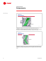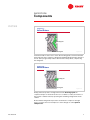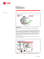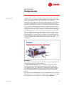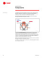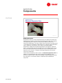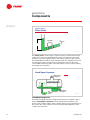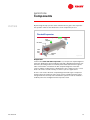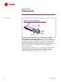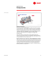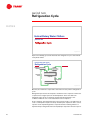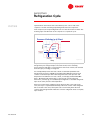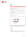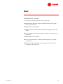
1
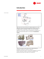
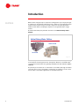
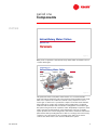
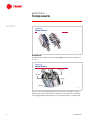
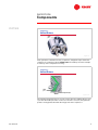
Air Conditioning
Clinic
Helical-Rotary
Water Chillers
One of the Equipment Series
TRG-TRC012-EN
Helical-Rotary
Water Chillers
One of the Equipment Series
A publication of
The Trane Company—
Worldwide Applied Systems Group
Preface
Helical-Rotary Water Chillers
A Trane Air Conditioning Clinic
Figure 1
The Trane Company believes that it’s incumbent on manufacturers to serve the
industry by regularly disseminating information gathered through laboratory
research, testing programs and field experience.
The Trane Air Conditioning Clinic series is one means of knowledge sharing.
It’s intended to acquaint a nontechnical audience with various fundamental
aspects of heating, ventilating, and air conditioning.
We’ve taken special care to make the clinic as uncommercial and
straightforward as possible. Illustrations of Trane products only appear in cases
where they help convey the message contained in the accompanying text.
This particular clinic introduces the reader to the concept of helical-rotary
water chillers.
ii
© 1999 American Standard Inc. All rights reserved
TRG-TRC012-EN
Contents
Introduction ............................................................1
period one
Components ...........................................................3
Compressor .............................................................4
Oil Separator ............................................................8
Condenser ...............................................................9
Expansion Device ...................................................11
Liquid/Vapor Separator ...........................................12
Evaporator .............................................................13
Controls and Starter ...............................................15
period two
Refrigeration Cycle .............................................16
period three Compressor Capacity Control .........................21
period four
Maintenance Considerations ...........................25
period five
Application Considerations ..............................31
Air-Cooled or Water-Cooled Condensing .................31
Condensing Temperature Control ...........................33
Constant or Variable Evaporator Water Flow ...........35
Short Evaporator Water Loops ................................36
Equipment Certification Standards ..........................38
period six
Review ....................................................................40
Quiz ..........................................................................44
Answers .................................................................46
Glossary .................................................................47
TRG-TRC012-EN
iii
iv
TRG-TRC012-EN
Introduction
notes
Chilled
Water
System
Figure 2
Water chillers are used in a variety of air conditioning and process cooling
applications. They are used to make cold water that can be transported
throughout a facility using pumps and pipes. This cold water can be passed
through the tubes of coils in order to cool the air in an air conditioning
application or it can provide cooling for a manufacturing or industrial process.
Systems that employ water chillers are commonly called chilled water
systems.
centrifugal
absorption
helical-rotary
Figure 3
There are several types of water chillers that are differentiated by the
refrigeration cycle they use or the type of compressor.
Absorption water chillers make use of the absorption refrigeration cycle and do
not have a mechanical compressor involved in the refrigeration cycle.
Absorption water chillers are the subject of a separate clinic.
TRG-TRC012-EN
1
Introduction
notes
Water chillers using the vapor-compression refrigeration cycle vary by the type
of compressor used. Reciprocating and scroll compressors are typically used in
smaller chillers. Helical-rotary (or screw) compressors are typically used in
medium-sized chillers. Centrifugal compressors are typically used in larger
chillers.
As mentioned earlier, this particular clinic discusses helical-rotary water
chillers.
Helical-Rotary Water Chillers
water-cooled
air-cooled
Figure 4
Helical-rotary water chillers can be either air-cooled or water-cooled, referring
to the method of rejecting heat to the atmosphere. Both air-cooled and watercooled helical-rotary chillers are generally available from 70 to 450 tons [200 to
1500 kW].
The primary focus in Period 1 is on the water-cooled chiller, although it includes
some discussion of air-cooled chiller components. A comparison of air-cooled
versus water-cooled chiller applications is included in Period 5.
2
TRG-TRC012-EN
period one
Components
notes
Helical-Rotary Water Chillers
period one
Figure 5
Many of the components of the helical-rotary water chiller are similar to those
of other chiller types.
components of a
Helical-Rotary Water Chiller
oil supply
system
compressor
motor
liquid/vapor
separator
oil separator
condenser
control
panel
starter
evaporator
Figure 6
This particular helical-rotary water chiller makes use of a shell-and-tube
evaporator where refrigerant evaporates inside the shell and water flows inside
tubes. The compressor is a twin-rotor, helical-rotary compressor. It uses a
suction-gas-cooled motor to operate the compressor. Another shell-and-tube
heat exchanger is used for the condenser, where refrigerant is condensed
inside the shell and water flows inside tubes. Refrigerant is metered through
the system using an electronic expansion valve. A liquid/vapor separator can be
used to enhance the effectiveness of the refrigeration cycle. An oil supply
system provides near oil-free refrigerant to the shells to maximize heat transfer
performance while providing lubrication and rotor sealing to the helical-rotary
compressor. A control panel is also provided on the chiller, and a starter
connects the chiller motor to the electrical distribution system.
TRG-TRC012-EN
3
period one
Components
notes
compressor...
Helical Rotors
Figure 7
Compressor
The helical-rotary chiller uses 2 screw-like rotors to perform the compression
process.
compressor...
Helical Rotors
female rotor
male rotor
housing
slide valve
Figure 8
The rotors are meshed and fit, with very close tolerances, within a housing.
Only the male rotor is driven by the compressor motor. The lobes of the male
rotor engage and drive the female rotor, causing the 2 parts to counter-rotate.
4
TRG-TRC012-EN
period one
Components
notes
compressor...
Helical Rotors
intake
port
Figure 9
In the operation of the helical-rotary compressor, refrigerant vapor enters the
compressor housing through the intake port. The intake port in this example
is at the top of the compressor housing.
compressor...
Helical Rotors
intake
port
pocket of refrigerant vapor
Figure 10
The entering refrigerant vapor is at a low, suction pressure and fills the grooves
or pockets formed by the lobes of the rotors. As the rotors turn, they push the
pockets of refrigerant toward the discharge end of the compressor.
TRG-TRC012-EN
5
period one
Components
notes
compressor...
Helical Rotors
intake port
discharge port
Figure 11
Viewing the compressor from the side shows that after the pockets of
refrigerant travel to the right past the intake port area, the vapor, still at suction
pressure, is confined within the pockets by the compressor housing.
compressor...
Helical Rotors
discharge port
meshing point
Figure 12
Viewing the compressor from the top shows that rotation of the meshed rotor
lobes drives the trapped refrigerant vapor (to the right) ahead of the meshing
point.
6
TRG-TRC012-EN
period one
Components
notes
compressor...
Helical Rotors
discharge port
meshing point
Figure 13
Continued rotation of the rotors causes the meshing point to travel toward the
discharge end of the compressor, driving the trapped refrigerant vapor ahead of
it. This action progressively reduces the volume of the pockets, compressing
the refrigerant.
compressor...
Helical Rotors
discharge port
meshing point
Figure 14
Finally, when the pockets of refrigerant reach the discharge port the
compressed vapor is released. As the rotors continue to rotate, the volume of
the pockets is further reduced, squeezing the remaining refrigerant from the
cavities.
Notice that the refrigerant vapor enters and exits the compressor through
ports—no valves are used. Compressors of this design are called ported
compressors.
TRG-TRC012-EN
7
period one
Components
notes
Oil Separator
refrigerant vapor
to condenser
refrigerant vapor
and oil mixture
oil return to sump
Figure 15
Oil Separator
The oil leaves the compressor entrained within the discharged refrigerant
vapor.
The oil is recovered from the discharged refrigerant by an oil separator, which
can have an efficiency of greater than 99%. The separator consists of a vertical
cylinder surrounding an exit passageway. As the refrigerant-and-oil mixture is
discharged into this passageway the oil is forced outward by centrifugal force,
collects on the walls of the cylinder, and drains to the bottom. This accumulated
oil drains out of the cylinder and collects in the oil sump located near the
bottom of the chiller.
The oil sump is heated to ensure proper lubrication and minimize refrigerant
condensation in the sump.
Oil Supply System
oil
separator
rotor bearings
rotor
refrigerant
vapor to
condenser
oil tank
sump
master
solenoid
valve
oil filter
compressor
2
1
Figure 16
Oil that collects in the oil sump is at condensing pressure during compressor
8
TRG-TRC012-EN
period one
Components
notes
operation and is, therefore, constantly moving to lower pressure areas of the
chiller. In this system, oil flows in 2 distinct paths, each performing a separate
function: 1) bearing lubrication and cooling and 2) rotor oil injection.
Oil leaves the sump and passes through an oil filter and master solenoid valve.
The master solenoid valve is used to isolate the sump from the low-pressure
side of the system when the compressor is shut down, preventing oil migration.
The first path is for lubricating and cooling the compressor bearings ➀. Oil is
routed to the bearings located in the rotor and bearing housing. Each housing is
vented to the suction side of the compressor so that oil leaving the bearings is
routed through the rotors, to the oil separator, and then back to the oil sump.
The second path is for lubricating and sealing the compressor rotors ➁. Oil is
injected along the bottom or top of the compressor rotors inside the housing.
Its main purpose is to seal the rotor-to-rotor and rotor-to-housing clearances.
This seal provides a barrier between the high- and low-pressure cavities of the
compressor. Additionally, oil lubricates the male-to-female rotor drive
arrangement.
water-cooled
Condenser
refrigerant vapor
baffle
cooling
tower
water
subcooler
liquid
refrigerant
tube bundle
Figure 17
Condenser
The high-pressure refrigerant vapor, now stripped of oil droplets, leaves the oil
separator and continues on to the condenser.
In a water-cooled condenser, water is pumped through the tubes of this
shell-and-tube heat exchanger while refrigerant vapor fills the shell space
surrounding the tubes. The condenser has a baffle plate that helps distribute
the refrigerant evenly within the shell. As heat is transferred from hot, highpressure refrigerant vapor to the water, refrigerant condenses on the tube
surfaces.
The condensed liquid refrigerant then collects in the bottom of the shell where
the lower tubes are now submerged, resulting in further cooling, or subcooling,
of the refrigerant. This arrangement is called an integral subcooler.
TRG-TRC012-EN
9
period one
Components
notes
Cooling water flows first through the lower tubes of the condenser and then
through the upper tubes. This produces a nearly constant temperature
difference between the downward moving refrigerant and the tube surfaces,
resulting in a uniform heat transfer rate within the tube bundle.
Subcooled liquid refrigerant leaves the condenser (subcooler) and flows
through the liquid line to the expansion device.
air-cooled
Condenser
propeller fan
condenser
coil
outdoor air
subcooler
Figure 18
In a typical air-cooled condenser, propeller-type fans are used to draw
outdoor air over a fin-tube heat transfer surface. The hot, high-pressure
refrigerant vapor flows through the tubes as heat is transferred to the cooler
outdoor air. The resulting reduction in the heat content of the refrigerant vapor
causes it to condense into liquid. Within the final few lengths of condenser
tubing the condensed liquid refrigerant is subcooled.
Again, subcooled liquid refrigerant leaves the condenser (subcooler) and flows
through the liquid line to the expansion device.
The differences between water-cooled and air-cooled chiller applications will be
discussed further in Period 5.
10
TRG-TRC012-EN
period one
Components
notes
expansion device…
Electronic Expansion Valve
Figure 19
Expansion Device
An expansion device is used to maintain the pressure difference between the
high-pressure (condenser) and low-pressure (evaporator) sides of the system,
as established by the compressor. This pressure difference allows the
evaporator temperature to be low enough to absorb heat from the water being
cooled, while also allowing the refrigerant to be at a high enough temperature
in the condenser to reject heat to air or water at normally available
temperatures. High-pressure liquid refrigerant flows through the expansion
device, causing a large pressure drop that reduces the refrigerant pressure to
that of the evaporator. This pressure reduction causes a small portion of the
liquid to boil off, or flash, cooling the remaining refrigerant to the desired
evaporator temperature.
In this chiller, the expansion device used is an electronic expansion valve. In
addition to maintaining the high- and low-side pressure difference, the
electronic expansion valve controls the quantity of liquid refrigerant entering
the evaporator to ensure that it will be completely vaporized within the
evaporator.
TRG-TRC012-EN
11
period one
Components
notes
expansion device…
Orifice Plates
to
evaporator
orifice plates
H
Figure 20
The orifice plate is another type of expansion device found in helical-rotary
chillers. The column of liquid refrigerant creates a head pressure at its base,
allowing it to pass through the orifices and undergo a pressure drop equal to
the head (H) before it flashes. As the load decreases, less refrigerant is moved
throughout the chiller, causing the level of the liquid column to drop. This
causes additional flashing at the orifice plate which, in turn, results in feeding
less liquid to the evaporator.
Liquid/Vapor Separator
refrigerant vapor
to compressor
from
expansion
device
liquid refrigerant
to evaporator
Figure 21
Liquid/Vapor Separator
The mixture of liquid and vapor refrigerant that leaves the expansion device
enters a liquid/vapor separator. Here the liquid refrigerant settles to the
bottom of the chamber and the vapor is drawn off the top and routed directly to
the suction side of the compressor. The remaining liquid refrigerant is then
routed to the evaporator.
12
TRG-TRC012-EN
period one
Components
notes
By removing the vapor portion of the mixture before it gets to the evaporator
the separator enhances the effectiveness of the evaporation process.
Flooded Evaporator
refrigerant vapor
liquid
refrigerant
chilled
water
supply
tube bundle
chilled
water
return
liquid level
sensor
Figure 22
Evaporator
In the flooded shell-and-tube evaporator cool, low-pressure liquid refrigerant
enters the distribution system inside the shell and is distributed uniformly over
the tubes, absorbing heat from relatively warm water that flows through the
tubes. This transfer of heat boils the film of liquid refrigerant on the tube
surfaces and the resulting vapor is drawn back to the compressor. The cooled
water can now be used in a variety of comfort or process applications.
A sensor can monitor the level of liquid refrigerant in this type of evaporator
and the electronic expansion valve can be used to carefully meter the liquid
refrigerant flow to the evaporator’s distribution system in order to maintain a
relatively low level of refrigerant in the evaporator shell.
TRG-TRC012-EN
13
period one
Components
notes
Direct Expansion Evaporator
chilled
water
supply
baffles
chilled
water
return
refrigerant
vapor
liquid
refrigerant
tube bundle
Figure 23
Another type of evaporator found in helical-rotary chillers is the direct
expansion (DX) shell-and-tube evaporator. In this type of evaporator the
cool, low-pressure liquid refrigerant flows through the tubes and water fills the
surrounding shell. As heat is transferred from the water to the refrigerant, the
refrigerant boils inside the tubes and the resulting vapor is drawn to the
compressor. Baffles within the shell direct the water in a rising and falling flow
path over the tubes that carry the refrigerant. The resulting turbulence
improves heat transfer.
Since the tubes of a flooded evaporator contain water, they can be mechanically
cleaned without removing the refrigerant charge. The tubes of a direct
expansion evaporator must be chemically cleaned. Additionally, flooded
evaporators are typically more effective, but are more costly.
14
TRG-TRC012-EN
period one
Components
notes
Controls And Starter
control
panel
starter
Figure 24
Controls and Starter
A microprocessor-based control panel is provided on the chiller to provide
accurate chilled water control as well as monitoring, protection, and adaptive
limit functions. These controls monitor the chiller’s operation and prevent the
chiller from operating outside of its limits. They can compensate for unusual
operating conditions while keeping the chiller running by modulating system
components, rather than simply tripping off due to a safety setting.
Furthermore, when problems do occur, diagnostic messages aid in
troubleshooting.
This control system not only provides accurate, optimized control and
protection for the chiller, but permits interfacing with a building automation
system for integrated system control. In a chilled water system, optimal control
is a system-wide issue, not just a chiller issue.
Because compressor motors create such a large electrical load, they cannot be
started and stopped using a simple switch or plug. A starter provides a linkage
between the motor and the electrical distribution system. Its primary function is
to connect (start) and disconnect (stop) the chiller from the line. The starter also
includes a transformer that provides power to the chiller control panel and
components to perform overload protection and current-limiting functions.
Finally, the application of a chiller starter also requires considering a means of
disconnect and short circuit protection.
TRG-TRC012-EN
15
period two
Refrigeration Cycle
notes
Helical-Rotary Water Chillers
period two
Figure 25
A pressure-enthalpy (p-h) chart illustrates the refrigeration cycle of the helicalrotary water chiller.
helical-rotary water chiller
Refrigeration Cycle
liquid/vapor
separator
compressor
expansion
device
evaporator
oil separator
condenser
Figure 26
But first, lets review the components of the helical-rotary chiller’s refrigeration
cycle...
Refrigerant vapor leaves the evaporator and flows to the compressor where it is
compressed to a higher pressure and temperature. Oil is removed from
refrigerant vapor in the oil separator and the refrigerant travels to the
condenser while the oil is recirculated back to the compressor.
In the condenser, the refrigerant vapor rejects heat to water or air and leaves as
a sub-cooled liquid. The pressure drop created by the expansion device causes
a portion of the liquid refrigerant to evaporate and the resulting mixture of
liquid and vapor refrigerant enters the liquid/vapor separator. Here the vapor is
16
TRG-TRC012-EN
period two
Refrigeration Cycle
notes
separated from the mixture and routed directly to the suction side of the
compressor and the remaining liquid refrigerant enters the evaporator.
In the evaporator, the liquid refrigerant boils as it absorbs heat from water. The
resulting vapor is drawn back to the compressor to repeat the cycle.
pressure
Pressure–Enthalpy (p-h) Chart
147.5 psia
subcooled
liquid
mixture of
liquid and
vapor
%
$
[1.02 MPa]
MPa]
superheated
vapor
46.4 Btu/lb
Btu/lb
116.6 Btu/lb
Btu/lb
[256.4 kJ/kg]
[419.6 kJ/kg]
enthalpy
Figure 27
The pressure-enthalpy chart is simply a plot of the saturated properties of a
refrigerant. It plots refrigerant pressure (vertical axis) versus enthalpy
(horizontal axis). Enthalpy is a measurement of the heat content, both sensible
and latent, per pound [kg] of refrigerant.
For example, A represents the heat content of saturated liquid HFC-134a
refrigerant at 147.5 psia [1.02 MPa] and 104°F [40°C]. B represents the heat
content of saturated vapor HFC-134a refrigerant at the same pressure and
temperature. The difference in heat content, or enthalpy, between A and B—
that is, 70.2 Btu/pound [163.2 kJ/kg]—is the amount of heat required to
transform 1 pound [1 kg] of saturated liquid refrigerant to saturated refrigerant
vapor at the same pressure and temperature.
If the heat content of the refrigerant at any pressure falls to the right of the
curve, the vapor is superheated. Similarly, if the heat content of the refrigerant
falls to the left of the curve, the liquid is subcooled. Finally, when the heat
content of the refrigerant falls inside the curve the refrigerant exists as a liquid/
vapor mixture.
TRG-TRC012-EN
17
period two
Refrigeration Cycle
notes
helical-rotary water chiller
Refrigeration Cycle
condenser
pressure
5
expansion
device
2
3
4
liquid/vapor
separator
7
6
evaporator
enthalpy
compressor
1
Figure 28
The theoretical vapor-compression refrigeration cycle for a helical-rotary water
chiller can be plotted on a pressure-enthalpy chart.
The refrigerant leaves the evaporator as saturated vapor ➀ and flows to the
suction end of the compressor where it enters the compartment for the suctiongas-cooled motor. Here the refrigerant flows across and cools the motor, then
enters the compression chamber. The refrigerant vapor is compressed in the
compressor to a high pressure and temperature ➁. Energy input to the motor
and compressor is imparted to the refrigerant as superheat. Superheated
refrigerant vapor leaves the compressor and enters the condenser.
Water or air flowing through the condenser absorbs heat from the hot, highpressure refrigerant. This reduction in the heat content of the refrigerant vapor
causes it to desuperheat ➂, condense into liquid ➃, and further sub-cool ➄
before leaving the condenser to travel to the expansion device.
The pressure drop created by the expansion process causes a portion of the
liquid refrigerant to evaporate. The evaporating refrigerant absorbs heat from
the remaining liquid refrigerant. The resulting mixture of cold liquid and vapor
refrigerant enters the liquid/vapor separator ➅. Here the vapor is separated
from the mixture and routed directly to the suction side of the compressor ➀
and the remaining liquid refrigerant enters the evaporator ➆.
The cool low-pressure liquid refrigerant enters the distribution system in the
evaporator shell and is distributed over the tubes in the evaporator tube
bundle, absorbing heat from water that flows through the tubes. This transfer
of heat boils the film of liquid refrigerant on the tube surfaces and the resulting
vapor is drawn back to the compressor ➀ to repeat the cycle.
18
TRG-TRC012-EN
period two
Refrigeration Cycle
notes
helical-rotary water chillers…
Refrigerants
▲
HCFC-22
▲
HFC-134a
▲
HFC-404a
▲
HFC-407c
▲
HFC-410a
Figure 29
Manufacturers are continuously improving their designs of helical-rotary water
chillers. New chillers need to be designed around the characteristics of the
refrigerant. Today there are 5 strong candidates for use with positivedisplacement, helical-rotary chillers. They are HCFC-22, HFC-134a, HFC-404a,
HFC-407c and HFC-410a.
TRG-TRC012-EN
19
period two
Refrigeration Cycle
notes
refrigerants…
Thermodynamic Characteristics
percent
efficiency
160
140
120
100
80
60
40
20
0
HCFC-22
HFC-134a
capacity
HFC-404a
pressure
HFC-407c
HFC-410a
Figure 30
Today the most commonly used refrigerant in helical-rotary chillers is HCFC-22.
Due to the scheduled phaseout of HCFC-22, most helical-rotary chillers will be
redesigned using HFC refrigerants. Many challenges are encountered when
redesigning a chiller to use a refrigerant with different thermodynamic
characteristics. This is due to the different efficiency, capacity, and operating
pressure characteristics of each of the refrigerants.
Take a closer look at each of these issues by examining the effects of using
different refrigerants in the same helical-rotary chiller designed for use with
HCFC-22.
■ Efficiency – In order to meet today’s high standards of energy efficiency,
chillers using refrigerants with a lower thermal efficiency, such as HFC-404a and
HFC-410a, will require larger heat exchangers and more efficient compressors.
These changes add to the product cost and increase the physical size of the
chiller.
■ Capacity – HFC-134a has a lower capacity compared to HCFC-22, which
means more refrigerant needs to be pumped through the chiller to achieve the
same capacity. This can be accomplished by using a larger compressor or
increasing the speed of the compressor. Both tend to increase product cost and
design complexity. On the other hand, HFC-410a has a higher capacity
compared to HCFC-22, which means less refrigerant needs to be pumped
through the chiller to achieve the same capacity. The advantage is that smaller,
less expensive compressors can be used.
■ Operating Pressure – A refrigerant that operates at a higher pressure
requires heat exchangers and pressure vessels to be designed for the higher
pressure. This adds cost. Conversely, higher pressure refrigerants have a
greater density. As density increases, the required amount of refrigerant
decreases, meaning that smaller or slower-speed compressors can be used.
Lower pressure refrigerants, such as HFC-134a, will require larger or higherspeed compressors in order to achieve the same capacity as a similar chiller
using HCFC-22.
20
TRG-TRC012-EN
period three
Compressor Capacity Control
notes
Helical-Rotary Water Chillers
period three
Figure 31
The capacity of the helical-rotary compressor presented in this clinic is
controlled by a slide valve that is an integral part of the compressor housing.
Other helical-rotary compressor designs may use a variety of methods to vary
capacity. Some of these methods are similar in function to the slide valve
presented in this period. One major difference is whether the compressor is
designed to unload in steps, like a reciprocating compressor, or if it has variable
unloading.
Slide Valve
axial
discharge
port
radial
discharge
port
slide valve
Figure 32
The position of the slide valve along the rotors controls the volume of
refrigerant vapor being delivered by the compressor, by varying the amount of
rotor length actually being used for compression.
Note that the compressor discharge has 2 components. First, a port within the
slide valve provides a radial discharge path. Second, a port within the endplate of the compressor housing provides an axial discharge path.
TRG-TRC012-EN
21
period three
Compressor Capacity Control
notes
slide valve position...
Full Load
compressor
discharge
slide valve
(closed)
axial port
radial port
Figure 33
At full load, the slide valve is closed. The compressor pumps its maximum
volume of refrigerant, discharging it through both the radial and axial ports.
slide valve position...
Part Load
slide valve
to suction
open
compressor
discharge
axial port
radial port
valve
opening
Figure 34
At part load, the slide valve modulates toward the open position. The opening
created by the valve movement allows refrigerant vapor to bypass from the
rotor pockets back to the suction side of the compressor. This reduces the
volume of vapor available for the compression process. It also reduces the
amount of rotor length available for compression. In this manner, the volume of
refrigerant that is pumped by the compressor is varied, unloading it to balance
the existing chiller load.
22
TRG-TRC012-EN
period three
Compressor Capacity Control
notes
compressor capacity control...
Unloading
slide valve
to suction
compressor
discharge
open
radial port
valve
opening
Figure 35
As the slide valve continues to open, further unloading the compressor, its
radial discharge port eventually travels past the opening in the compressor
housing. Once this occurs, all of the refrigerant vapor being pumped by the
compressor is discharged through the axial port in the compressor’s end-plate.
The compressor discharge ports and slide valve are designed to allow the
compressor to operate efficiently over a wide range of conditions.
TRG-TRC012-EN
23
period three
Compressor Capacity Control
notes
Slide Valve Operation
high-pressure
refrigerant vapor
load
valve
to lowpressure
compressor
housing
slide valve
operator
shaft
spring
unload
valve
piston
cylinder
Figure 36
The slide valve is operated by a piston and cylinder assembly. Extension and
retraction of the operator shaft positions the slide valve along the compressor
rotors.
High-pressure refrigerant vapor, controlled by 2 solenoid valves, is fed to or
bled from this assembly in order to position the valve. To close the slide valve
and load the compressor, the load valve is opened and the unload valve is
closed. This allows high-pressure refrigerant vapor to enter the cylinder from
the discharge of the compressor, extending the operator shaft and moving the
slide valve so that it covers more of the rotor length.
Conversely, to open the slide valve and unload the compressor, the load valve
is closed and the unload valve is opened. This allows the high-pressure
refrigerant vapor to bleed out of the cylinder into the low-pressure area within
the compressor housing. A spring helps return the piston, retracting the
operator shaft and moving the slide valve such that the rotors are more
uncovered. This reduces the effective length of the rotors, which are
compressing vapor.
On shutdown the unload solenoid valve is energized and the spring drives the
slide valve to the fully-unloaded position. This ensures that the compressor
always starts fully unloaded.
When both solenoid valves are closed, the operator shaft holds the slide valve
at its current position.
24
TRG-TRC012-EN
period four
Maintenance Considerations
notes
Helical-Rotary Water Chillers
period four
Figure 37
This period discusses general maintenance requirements of helical-rotary water
chillers. Although some of the information applies specifically to the design
presented in this clinic, requirements for other helical-rotary chiller designs are
also included.
helical-rotary water chillers
Maintenance Considerations
▲
Operating log
▲
Mechanical
components
▲
Heat transfer
surfaces
▲
Fluid analysis
Figure 38
Once a helical-rotary chiller is installed and put into operation, it usually
continues to function without a full-time attendant. In many cases, the machine
starts and stops on a schedule controlled by the building automation system or
a simple time clock. The only daily maintenance requirement is to check the
operating log.
Water chillers are designed for maximum reliability with a minimum amount of
maintenance. Like all large mechanical systems, however, certain routine
maintenance procedures are either required or recommended.
TRG-TRC012-EN
25
period four
Maintenance Considerations
notes
operating log
ASHRAE Guideline 3
▲
Chilled water inlet and outlet
temperatures and pressures
▲
Compressor refrigerant suction
and discharge temperatures
▲
Chilled water flow
▲
Refrigerant level
▲
Evaporator refrigerant
temperature and pressures
▲
Oil pressures, temperature, and
levels
▲
Evaporator approach
temperature
▲
Addition of refrigerant
▲
Condenser water inlet and
outlet temperatures and
pressures
▲
Addition of oil
▲
Vibration levels
▲
Condenser water flow
▲
Condenser refrigerant
temperature and pressures
▲
Condenser approach
temperature
Figure 39
The American Society of Heating, Refrigerating and Air Conditioning Engineers
(ASHRAE) has published Guideline 3 titled Reducing Emission of Halogenated
Refrigerants in Refrigeration and Air Conditioning Equipment and Systems.
This guideline includes a recommended list of data points to be logged daily for
each chiller. Much of this data may be available through the chiller’s control
panel.
Special attention should be given to the following:
■ Review the operating log and trends
■ Measure the oil pressure drop to determine if the oil filter needs to be
replaced
■ Measure refrigerant superheat and subcooling
■ Measure both the refrigerant and oil charges
26
TRG-TRC012-EN
period four
Maintenance Considerations
notes
maintenance considerations
Mechanical Components
▲
▲
Required maintenance
◆
Compressor and motor: no maintenance required
◆
Controls: no maintenance or calibration required
Recommended maintenance
◆
Visually inspect overall unit
◆
Inspect safety controls and electrical components
◆
Tighten electrical connections
◆
Check for leaks
◆
Test vent piping
Figure 40
Direct-drive, semi-hermetic compressor designs require no periodic
maintenance on the compressor/motor assembly. The compressor contains
only 3 main moving parts: the male and female rotors and the slide valve. The
semi-hermetic motor eliminates the need for external shaft seals associated
with open motors. These seals are a prime source of oil and refrigerant leaks. It
also eliminates annual coupling and seal inspections, alignment, and shaft seal
replacement.
With the advent of microprocessor-based controls, the control panel and
auxiliary controllers require no recalibration or maintenance. Remote-mounted
electronic sensors send information to the unit controller, which can be
connected to a building automation system in order to communicate
information and allow for system-level optimization. These systems can notify
the operator with an alarm or diagnostic message when a problem occurs.
Like any mechanical equipment, a daily visual inspection of the chiller is
recommended to look for oil leaks, condensation, loosened electrical or control
wiring, or signs of corrosion. Special attention should be given to the safety
controls and electrical components.
It is recommended that a qualified service technician check the chiller annually
for leaks. In the normal service of any air conditioning system, the Unites States
EPA mandates that whenever a refrigeration circuit is opened, recovery of the
refrigerant is required.
Finally, the vent piping of all pressure relief valves should be leak-tested
annually for the presence of refrigerant to detect improperly sealed valves.
Leaking relief valves should be replaced.
TRG-TRC012-EN
27
period four
Maintenance Considerations
notes
maintenance considerations
Mechanical Components
▲
Other design-specific requirements:
◆
Change oil when oil analysis dictates
◆
Replace oil filter periodically
◆
Replace filter drier periodically
◆
Clean oil strainers annually
◆
Check shaft alignment annually
◆
Check coupling annually
◆
Replace shaft seal every 2 to 4 years
◆
Compressor teardown inspection every 5 to 10 years
Figure 41
Some helical-rotary compressor designs do require periodic maintenance of
mechanical system components. This includes oil and refrigerant filter changes,
oil strainer changes, and a compressor rotor inspection.
Open-motor compressor designs require shaft alignment, coupling inspection,
bearing lubrication, and cleaning of the motor windings, rotor ends, and fan
blades on a quarterly or annual basis.
In all cases, strictly follow the manufacturer’s published maintenance
requirements and recommendations.
maintenance considerations
Heat Transfer Surfaces
▲
Recommended maintenance
◆
Use a qualified water treatment
specialist
◆
Clean condenser tubes as
needed (water-cooled)
◆
Clean water-side strainers
◆
Test tubes every 3 years
◆
Clean condenser coils as
needed (air-cooled)
Figure 42
Optimum performance of heat transfer components depends on keeping the
heat transfer surfaces free from scale and sludge. Even a very thin deposit of
scale can substantially reduce heat transfer capacity. Owners of water-cooled
chillers should engage the services of a qualified water treatment specialist to
28
TRG-TRC012-EN
period four
Maintenance Considerations
notes
determine the level of water treatment required to remove contaminants from
the cooling tower water.
Scale deposits are best removed by chemical means. The water-cooled
condenser is commonly isolated from the rest of the cooling tower water circuit
by valves, and a pump circulates cleaning solution through the condenser
tubes.
Sludge is removed mechanically. This involves removing the water boxes from
the condenser and loosening the deposits with a stiff-bristled brush. The
loosened material is then flushed from the tubes with clear water. As part of this
procedure, the strainers on both the chilled water and cooling tower water
circuits should be cleaned every year.
Every 3 years, or more frequently for process or critical applications, it is
recommended that a qualified service organization perform non-destructive
tube inspections on both the evaporator and condenser tubes. The eddycurrent tube test is a common method.
Rarely, problems may arise that cause refrigerant or water leaks. These must be
repaired immediately.
For air-cooled chillers, the condenser coils should be cleaned at least annually
in order to maintain proper efficiencies and operating conditions. Follow the
manufacturer’s instructions to avoid damage to the coils.
maintenance considerations
Fluid Analysis
▲
▲
Oil analysis
◆
Conduct annual analysis to verify
system integrity
◆
Measure oil pressure drop to
determine if filter needs changing
◆
Measure charge
Refrigerant charge
◆
Measure charge and trim as
necessary
◆
Measure superheat and subcooling
Figure 43
Probably the most important annual maintenance task required for helicalrotary water chillers is an oil analysis. It may be conducted more frequently for
chillers that run continuously or more often than normal. This test, performed
by a qualified laboratory, verifies the integrity of the refrigeration system by
testing the moisture, acidity, and metal concentration levels. This analysis can
determine where problems exist or could potentially develop. By taking oil
samples on a regular basis, normal operating trends for the compressor and
bearing metals can be analyzed. As opposed to changing the oil once a year
whether it needs it or not, regular oil analyses can be used to determine proper
oil change intervals as well as predict major problems before they occur.
TRG-TRC012-EN
29
period four
Maintenance Considerations
notes
Refrigerant analysis measures contamination levels and determines suitability
for continued use. It can also determine the acceptability of recycled refrigerant
for reuse. Refrigerant analysis helps extend the life of the existing charge and
ensures that the chiller is operating at peak efficiency.
Logging the oil and refrigerant charges, and examining the trends of this data,
can help identify potential problems before they occur.
maintenance considerations
Fluid Analysis
▲
Why perform regular oil analyses?
◆
Helps reduce maintenance costs
◆
Detects problems without
compressor disassembly
◆
Extends service life of oil charge
◆
Reduces environmental problems
related to oil disposal
◆
Helps maintain compressor
efficiency and reliability
◆
Helps lower refrigerant emissions
Figure 44
An oil analysis is a key preventive maintenance measure and should be
conducted at least annually. It will help the compressor last longer while
improving chiller efficiency and reducing refrigerant emissions. A certified
chemical laboratory has years of experience in analyzing oil and refrigerant
from all types of compressors.
Often the chiller manufacturer can provide this service.
30
TRG-TRC012-EN
period five
Application Considerations
notes
Helical-Rotary Water Chillers
period five
Figure 45
There are several considerations to address when applying helical-rotary water
chillers, including:
■ Air-cooled or water-cooled condensing
■ Condensing temperature control
■ Constant or variable evaporator water flow
■ Short evaporator water loops
■ Equipment certification standards
This section is by no means the entire list of considerations, but is
representative of some of the key issues.
condenser types…
Air-Cooled or Water-Cooled
Figure 46
Air-Cooled or Water-Cooled Condensing
Although this is not a new consideration, the question of which condenser type
to apply continues to receive attention. A major advantage of air-cooled chillers
TRG-TRC012-EN
31
period five
Application Considerations
notes
is the elimination of the cooling tower. This eliminates the concerns and
maintenance requirements associated with water treatment, makeup water
availability and quality, tower mechanical maintenance, freeze protection, and
chiller condenser tube cleaning. This reduced maintenance requirement is
particularly attractive since it can substantially reduce operating costs.
Another advantage of an air-cooled chiller is its delivery as a “packaged
system.” Reduced design time, simplified installation, higher reliability, and
single-source responsibility are all factors that make the factory packaging of
the condenser, compressor, and evaporator a major benefit. A water-cooled
chiller has the additional requirement of condenser water piping, pump,
cooling tower, and controls.
Air-cooled chillers are often selected in buildings with a requirement for yearround cooling that cannot be met with an air-side economizer. Air-cooled
condensers have the ability to operate in below-freezing weather without the
problems associated with operating the cooling tower in low-ambient
conditions. Cooling towers may require special sequences of operation, basin
heaters, or even an indoor sump for safe operation in freezing weather.
air-cooled or water-cooled
Comparison
air-cooled
water-cooled
▲
Lower maintenance
▲
Greater energy efficiency
▲
Packaged system
▲
Longer equipment life
▲
Better low ambient
operation
Figure 47
Water-cooled chillers are generally more energy efficient. The efficiency
advantage of a water-cooled chiller, however, is much less when the additional
cooling tower and condenser pump energy costs are considered. Additionally,
this efficiency advantage may lessen at part-load conditions since the dry bulb
temperature tends to drop faster than the wet bulb temperature and the aircooled chiller benefits from greater condenser relief.
Performing a comprehensive energy analysis is the best method of estimating
the system operating cost difference between air-cooled and water-cooled
systems.
Water-cooled chillers typically last longer than air-cooled chillers. This
difference is due to the fact that the air-cooled chiller is installed outdoors,
whereas the water-cooled chiller is installed indoors. Also, using water as the
condensing fluid allows the water-cooled chiller to operate at lower pressures
32
TRG-TRC012-EN
period five
Application Considerations
notes
and temperatures that the air-cooled chiller. Generally, air-cooled chillers last 15
to 20 years, while water-cooled chillers last 20 to 25 years.
To summarize the comparison of air-cooled and water-cooled helical-rotary
chillers, air-cooled chiller advantages include lower maintenance cost, a prepackaged system for easier design and installation, and better low ambient
operation. Water-cooled chiller advantages include greater energy efficiency (at
least at design conditions) and longer equipment life.
Condensing Temperature Control
cooling tower
condenser
water
pump
condenser
Figure 48
Condensing Temperature Control
All chillers require a minimum pressure difference between the evaporator and
condenser to ensure proper management of oil and refrigerant. This minimum
pressure difference depends on the chiller design and controls. The most
common method of maintaining this pressure difference at the various load
conditions is to control the condensing temperature by varying the temperature
or flow rate of water (or air) flowing through the condenser. By controlling the
condensing temperature, most helical-rotary water chillers can start and
operate over a wide range of conditions.
Controlling condensing temperature: 1) maintains chiller efficiency, 2)
maintains the required pressure differential between the evaporator and
condenser for controlled flow through the refrigerant metering system, and 3)
prevents the pressure imbalance that could cause oil loss problems.
Controlling the refrigerant pressure difference between the evaporator and
condenser of an air-cooled chiller is accomplished by varying the flow rate of
the air flowing through the condenser coils. This control is an integral part of
the chiller design.
TRG-TRC012-EN
33
period five
Application Considerations
notes
condensing temperature control
Cooling Tower Bypass
40°F
[4°C]
cooling tower
bypass
diverting
valve
65°F
[18°C]
55°F
[13°C]
condenser
Figure 49
Controlling the refrigerant pressure difference between the evaporator and
condenser of a water-cooled chiller is accomplished by varying the temperature
or flow rate of the water flowing through the condenser. The following are 5
common methods used to control condensing temperature:
1) Controlling the temperature of the water leaving the cooling tower by cycling
or varying the speed of the cooling tower fans
2) Using a cooling tower bypass pipe to mix warmer leaving-condenser water
with the colder tower water and control the temperature entering the condenser
as illustrated in the accompanying slide
3) Modulating a throttling valve to restrict the flow of water through the
condenser
4) Using a chiller bypass pipe to vary the flow rate of water through the
condenser
5) Employing a variable-speed drive on the condenser water pump to vary the
water flow rate through the condenser
Each of these strategies has its advantages and disadvantages, and selection of
the appropriate condensing temperature control scheme depends on the
specific application.
The water flow rate through the chiller’s condenser must stay between the
minimum and maximum condenser bundle flow rates as specified by the chiller
manufacturer.
34
TRG-TRC012-EN
period five
Application Considerations
notes
evaporator water flow…
Constant or Variable Flow
chilled
water
pump
evaporator
variable
speed
drive
Figure 50
Constant or Variable Evaporator Water Flow
In previous designs, chillers were required to maintain a constant flow rate of
water through the evaporator. This requirement has changed due to advances
in chiller controls. Increased sensing and control capabilities now allow chiller
manufacturers to design controls that monitor, and respond faster to,
fluctuating conditions.
While the chiller may be able to handle variable water flow through the
evaporator, the specific application of a chilled water system may not warrant
variable flow. As always, each application should be analyzed to determine if
variable evaporator water flow is warranted.
variable evaporator water flow
Limitations
▲
Maintain minimum and maximum water flow
rates through the chiller evaporator
▲
Rate at which evaporator water flow changes
must be kept below the corresponding limit to:
◆
Maintain the chilled water set point control
◆
Keep the chiller on line
◆
Protect the chiller from damage
Figure 51
The controls on many current chiller designs can properly control the chiller in
response to varying evaporator flow rates, with the following limitations:
TRG-TRC012-EN
35
period five
Application Considerations
notes
1) The water flow rate through the chiller’s evaporator must stay between the
minimum and maximum evaporator bundle flow rates as specified by the
chiller manufacturer. These limits depend on the specific details of the actual
evaporator bundle, such as the number of tubes, number of passes, and
geometry of the bundle. A method for sensing evaporator water flow through
each chiller is the only way to make sure the water flow rate stays within these
limits.
2) The rate which the evaporator water flow rate changes must be kept below a
specified level, which is dependent on the level of protection desired. For
example, the maximum rate of change in order to maintain chilled water
setpoint is more stringent than the maximum rate of change in order to keep
the chiller on line. There are 3 common levels of protection desired:
maintaining chilled water setpoint control, keeping the chiller on line, and
protecting the chiller from damage.
The limits for these different levels of protection should be obtained from the
chiller manufacturer.
Short Evaporator Water Loops
load
chilled
water
pump
evaporator
Figure 52
Short Evaporator Water Loops
Proper chilled water temperature control requires that the temperature of the
chilled water returning to the evaporator not change any faster than the chiller
controls can respond. The volume of water in the evaporator loop acts as a
buffer and ensures a slowly changing return water temperature and, therefore,
stable temperature control. If there is not a sufficient volume of water in the
loop to provide an adequate buffer, temperature control can be lost, resulting in
erratic system operation.
The chiller manufacturer should be consulted for volume requirements of the
evaporator water loop.
36
TRG-TRC012-EN
period five
Application Considerations
notes
Short Evaporator Water Loops
load
tank
chilled
water
pump
evaporator
Figure 53
Short water loops may be unavoidable in close-coupled or very small
applications, particularly in systems where the load consists of only a few air
handlers or processes.
To prevent the effect of a short water loop, a storage tank or large header pipe
can be added to the system to increase the volume of water in the loop and act
as a buffer to ensure a slowly changing return water temperature.
TRG-TRC012-EN
37
period five
Application Considerations
notes
equipment certification standards
ARI Standard 550/590
▲
Purpose
◆
▲
Establish definitions and
testing and rating
requirements
Scope
◆
Factory designed and
prefabricated water chillers
◆
Vapor-compression
refrigeration
◆
Air-cooled and water-cooled
condensing
Figure 54
Equipment Certification Standards
The Air Conditioning & Refrigeration Institute (ARI) establishes rating standards
for packaged HVAC equipment. ARI also certifies and labels equipment through
programs that involve random testing of a manufacturer’s equipment to verify
published performance.
The overall objective of ARI Standard 550/590–1998 is to promote consistent
rating and testing methods for all types and sizes of water chillers with an
accurate representation of actual performance. It covers factory-designed,
prefabricated water chillers, both air-cooled and water-cooled, using the vaporcompression refrigeration cycle.
38
TRG-TRC012-EN
period five
Application Considerations
notes
equipment certification standards
ARI Standard 550/590
▲
Standard rating conditions
◆
▲
Common system conditions for published ratings
Integrated Part Load Value (IPLV)
◆
Part-load efficiency rating
◆
Based on an “average” single-chiller installation
◆
Standard operating conditions
Figure 55
The standard rating conditions used for ARI certification represent typical
design temperatures and flow rates for which water-cooled and air-cooled
systems are designed. They are not suggestions for good design practice for a
given system, they are simply a common rating point. Trends toward improved
humidity control and energy efficiency have changed some of the actual
conditions selected for specific applications.
ARI’s part-load efficiency rating system establishes a single, blended estimate
of stand-alone chiller performance. The Integrated Part Load Value (IPLV)
calculator predicts chiller efficiency at the ARI standard rating conditions using
weighted averages representing a broad range of geographic locations,
building types, and operating-hour scenarios, both with and without an airside
economizer. While the weighted averages place greater emphasis on the partload operation of an average, single-chiller installation, they will not—by
definition—represent any particular installation.
Additionally, ARI notes that more than 80 percent of all chillers are installed in
multiple-chiller plants. Chillers in these plants exhibit different unloading
characteristics than the IPLV weighted formula indicates. Appendix D of the
Standard explains this further:
...The [IPLV] equation was derived to provide a representation of the average
part-load efficiency for a single chiller only. However, it is best to use a
comprehensive analysis that reflects actual weather data, building load
characteristics, operational hours, economizer capabilities, and energy drawn
by auxiliaries such as pumps and cooling towers, when calculating the chiller
and system efficiency. This becomes increasingly important with multiple
chiller systems because individual chillers operating within multiple chiller
systems are more heavily loaded than single chillers within single chiller
systems.
Remember that the ARI rating is a standardized representation. Many chillers
do not run at standard rating conditions and few are applied in single-chiller
installations. Performing a comprehensive energy analysis is the best method
of comparing the system operating cost difference between 2 chillers.
TRG-TRC012-EN
39
period six
Review
notes
Helical-Rotary Water Chillers
period six
Figure 56
Let’s review the main concepts that were covered in this clinic on helical-rotary
water chillers.
Review—Period 1
oil supply
system
compressor
motor
liquid/vapor
separator
oil separator
condenser
control
panel
starter
evaporator
Figure 57
In Period 1, the following components of a helical-rotary water chiller were
discussed: compressor, oil separator, oil supply system, condenser, expansion
device, liquid/vapor separator, evaporator, starter, and controls.
40
TRG-TRC012-EN
period six
Review
notes
Review—Period 2
condenser
pressure
5
expansion
device
2
3
4
liquid/vapor
separator
7
6
evaporator
compressor
1
Figure 58
enthalpy
In Period 2, the refrigeration cycle of the helical-rotary water chiller was
examined on a pressure-enthalpy chart. Also, the performance characteristics
of the various refrigerants were compared.
Review—Period 3
axial
discharge
port
radial
discharge
port
slide valve
Figure 59
In Period 3, the operation of the modulating slide valve was explained. The slide
valve is one method by which a helical-rotary compressor’s capacity is
controlled.
TRG-TRC012-EN
41
period six
Review
notes
Review—Period 4
▲
Maintenance considerations
◆
Operating log
◆
Mechanical components
◆
Heat transfer surfaces
◆
Fluid analysis
Figure 60
In Period 4, the general maintenance requirements of a helical-rotary water
chiller were discussed, including:
■ Recommended data to be logged daily
■ Required and recommended maintenance of the mechanical components
■ Required and recommended maintenance of the heat transfer surfaces
■ Recommended analysis of the oil and refrigerant
Review—Period 5
▲
Application considerations
◆
Air-cooled or water-cooled
◆
Condensing temperature control
◆
Constant or variable evaporator water flow
◆
Short evaporator water loops
◆
Equipment certification standards
Figure 61
In Period 5, several considerations in the application of helical-rotary water
chillers were presented. These included air-cooled or water-cooled condensing,
condensing temperature control, constant or variable evaporator water flow,
short evaporator water loops, and equipment certification standards.
42
TRG-TRC012-EN
period six
Review
notes
Figure 62
For more information, refer to the following references:
■ Trane product catalogs for helical-rotary water chiller products
(Trane literature order numbers RLC-DS-1, RLC-DS-2, RLC-DS-4, and RLC-DS-6)
■ Water-Cooled Series R® Chiller—Model RTHC Mechanical Operation
(RLC-EB-16)
■ Series R® CenTraVac® Chiller Condensing Water Temperature Control
(RLC-EB-4)
■ Multiple Chiller System Design And Control (CON-AM-21)
■ ARI Standard 550/590–1998: Implications For Chilled-Water Plant Design
(Trane Engineers Newsletter, 1999—volume 28, no. 1)
■ ASHRAE Handbook—Refrigeration
■ ASHRAE Handbook—Systems and Equipment
Visit the ASHRAE Bookstore at www.ashrae.org.
For information on additional educational materials available from Trane,
contact your local Trane sales office (request a copy of the Educational
Materials price sheet — Trane order no. EM-ADV1) or visit our online bookstore
at www.trane.com/bookstore/.
TRG-TRC012-EN
43
Quiz
Questions for Period 1
1 What components of the helical-rotary compressor are used to compress
the refrigerant?
2 What are the 2 functions of the oil supply system presented in this clinic?
3 In a flooded shell-and-tube evaporator, is the refrigerant flowing inside or
outside of the tubes?
4 Name 2 types of expansion devices commonly found in helical-rotary water
chillers.
Questions for Period 2
pressure
5
4
7
2
3
1
6
enthalpy
Figure 63
5 Using the pressure-enthalpy diagram in Figure 63, identify the following
processes of the helical-rotary water chiller’s refrigeration cycle:
a) ➀ to ➁
b) ➁ to ➄
c) ➄ to ➅
d) ➆ to ➀
6 Referring again to Figure 63, after the vapor is removed in the liquid/vapor
separator, to which point in the refrigeration cycle does it travel?
44
TRG-TRC012-EN
Quiz
Questions for Period 3
7 At full load, is the slide valve fully closed or fully open?
8 Explain how the slide valve varies the refrigerant flow rate through the
helical-rotary compressor.
Questions for Period 4
9 What document recommends the data points to be logged daily for each
chiller?
10 List 3 advantages to performing a regular oil analysis on a helical-rotary
water chiller.
Questions for Period 5
11 List 3 common methods of controlling condensing pressure in a watercooled chiller.
12 What are the 2 primary limitations with varying the flow rate of water
through the chiller evaporator?
TRG-TRC012-EN
45
Answers
1 Male and female screw rotors
2 Bearing lubrication and cooling, and rotor oil injection
3 Outside of the tubes
4 Electronic expansion valve and orifice plate
5) a) compression
b) condensation (desuperheat, condense, subcool)
c) expansion
d) evaporation
6 Point 1, the suction inlet of the compressor
7 Fully closed
8 At part load, the opening created by the slide valve movement allows
refrigerant vapor to bypass from the rotor pockets back to the suction side
of the compressor. This reduces the volume of vapor available for the
compression process. It also reduces the amount of rotor length available
for compression.
9 ASHRAE Guideline 3
10 Helps reduce maintenance costs, detects problems without compressor
disassembly, oil charges last longer, less environmental problems with
disposing of used oil, helps maintain the compressor’s efficiency and
reliability, and helps lower refrigerant emissions.
11 Cycling or varying the speed of the cooling tower fans, using a cooling
tower bypass pipe, modulating a throttling valve, using a chiller bypass
pipe, or employing a variable-speed drive on the condenser water pump.
12 The water flow rate through the chiller’s evaporator must stay between the
minimum and maximum evaporator bundle flow rates as specified by the
chiller manufacturer. The rate which the evaporator water flow rate changes
must be kept below a specified level.
46
TRG-TRC012-EN
Glossary
air-cooled condenser A type of condenser that rejects the heat of the
refrigerant to air flowing through it.
ARI Air Conditioning & Refrigeration Institute
ARI Standard 550/590 A publication, titled “Standard for Water Chilling
Packages Using the Vapor-Compression Cycle”, used to promote consistent
rating and testing methods for all types and sizes of water chillers. It covers
factory-designed, prefabricated water chillers, both air-cooled and watercooled, using the vapor-compression refrigeration cycle.
ASHRAE American Society of Heating, Refrigerating and Air Conditioning
Engineers
ASHRAE Guideline 3 A publication, titled “Reducing Emission of Halogenated
Refrigerants in Refrigeration and Air Conditioning Equipment and Systems”,
that includes a recommended list of data points to be logged daily for each
water chiller.
compressor The mechanical device used by the chiller to increase the
pressure and temperature of the refrigerant vapor.
condenser The region of the chiller where refrigerant vapor is converted to
liquid as it rejects heat to water or air.
control panel The microprocessor-based panel that monitor the chiller’s
operation, protects it from damage, provides the operator with data and
diagnostic messages, and permits interfacing with a building automation
system.
direct expansion (DX) shell-and-tube evaporator A type of evaporator where
refrigerant flows through the tubes and water fills the surrounding shell.
electronic expansion valve A type of expansion device that uses an
electronically-actuated valve to sense and control the flow rate of liquid
refrigerant to the evaporator.
enthalpy The property of a refrigerant indicating its total heat content, both
sensible and latent.
evaporator The region of the chiller where the system chilled water is
continuously cooled by flashing the refrigerant to vapor as it picks up heat from
the returning chilled water.
expansion device The component of the chiller used to reduce the pressure
and temperature of the refrigerant.
flooded shell-and-tube evaporator A type of evaporator where water flows
through the tubes and refrigerant fills the surrounding shell.
liquid/vapor separator The component of the chiller used to remove vapor
from the refrigerant mixture after it passes through the expansion device. This
TRG-TRC012-EN
47
Glossary
vapor is directed back to the compressor while the liquid refrigerant travels on
to the evaporator.
oil separator The component of the chiller used to remove oil from the
refrigerant vapor after it is discharged from the compressor. This oil is directed
back to the compressor.
orifice plate A type of expansion device that uses a fixed plate with holes
drilled in it to meter the flow rate of refrigerant to the evaporator.
ported compressors A type of compressor where the refrigerant vapor enters
and exits through ports—no valves are used.
pressure-enthalpy diagram A graphical representation of the saturated
properties of a refrigerant, plotting refrigerant pressure versus enthalpy.
rotor The part of the helical-rotary compressor used to trap and compress the
refrigerant vapor. The male and female rotors mesh together forming pockets
of refrigerant to move through the compressor.
slide valve The part of the helical-rotary compressor used to vary the flow rate
of refrigerant vapor through it.
subcooler The lower portion of the condenser that further cools the saturated
liquid refrigerant.
water-cooled condenser A type of condenser that rejects the heat of the
refrigerant to water flowing through it.
48
TRG-TRC012-EN
26447_ReplyCard.fm Page 1 Friday, August 13, 1999 3:37 PM
NO POSTAGE
NECESSARY
IF MAILED
IN THE
UNITED STATES
BUSINESS REPLY MAIL
FIRST-CLASS MAIL
PERMIT NO. 11
LA CROSSE, WI
POSTAGE WILL BE PAID BY ADDRESSEE
THE TRANE COMPANY
Attn: Applications Engineering
3600 Pammel Creek Road
La Crosse WI 54601-9985
NO POSTAGE
NECESSARY
IF MAILED
IN THE
UNITED STATES
BUSINESS REPLY MAIL
FIRST-CLASS MAIL
PERMIT NO. 11
LA CROSSE, WI
POSTAGE WILL BE PAID BY ADDRESSEE
THE TRANE COMPANY
Attn: Applications Engineering
3600 Pammel Creek Road
La Crosse WI 54601-9985
26447_ReplyCard.fm Page 2 Friday, August 13, 1999 3:37 PM
Comment Card
We want to ensure that our educational materials meet your ever-changing resource development needs.
Please take a moment to comment on the effectiveness of this Air Conditioning Clinic.
Helical-Rotary Water Chillers Level of detail (circle one)
Too basic
Just right
Too difficult
One of the Equipment Series
Rate this clinic from 1–Needs Improvement to 10–Excellent …
TRG-TRC012-EN
Content
1
2
3
4
5
6
7
8
9
10
Booklet usefulness
1
2
3
4
5
6
7
8
9
10
Slides/illustrations
1
2
3
4
5
6
7
8
9
10
Presenter’s ability
1
2
3
4
5
6
7
8
9
10
Training environment
1
2
3
4
5
6
7
8
9
10
Other comments?
_________________________________________________________
_______________________________________________________________________________
_______________________________________________________________________________
About me …
Type of business
Job function
Optional: name
phone
address
_________________________________________________________
_________________________________________________________
_________________________________________________________
_________________________________________________________
_________________________________________________________
Give the completed card to the
presenter or drop it in the mail.
Thank you!
The Trane Company • Worldwide Applied Systems Group
3600 Pammel Creek Road • La Crosse, WI 54601-7599
www.trane.com
An American-Standard Company
Response Card
We offer a variety of HVAC-related educational materials and technical references, as well as software tools
that simplify system design/analysis and equipment selection. To receive information about any of these
items, just complete this postage-paid card and drop it in the mail.
Education materials
Software tools
Air Conditioning Clinic series
About me …
Engineered Systems Clinic series
Name
____________________________________________
Trane Air Conditioning Manual
Title
____________________________________________
Trane Systems Manual
Business type ____________________________________________
Equipment selection
Phone/fax
System design & analysis
E-mail address ____________________________________________
_____________________
_____________________
Periodicals
Engineers Newsletter
Company
____________________________________________
Other?
_____________________________
Address
____________________________________________
____________________________________________
____________________________________________
Thank you for your interest!
The Trane Company • Worldwide Applied Systems Group
3600 Pammel Creek Road • La Crosse, WI 54601-7599
www.trane.com
An American-Standard Company
Literature Order Number
The Trane Company
Worldwide Applied Systems Group
3600 Pammel Creek Road
La Crosse, WI 54601-7599
www.trane.com
An American Standard Company
TRG-TRC012-EN
File Number
E/AV-FND-TRG-TRC012-899-EN
Supersedes
2803-15-888
Stocking Location
Inland-La Crosse
Since The Trane Company has a policy of continuous product improvement, it reserves the right to change
design and specifications without notice.