1
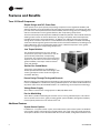
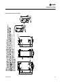
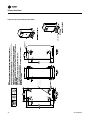
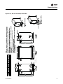
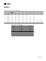
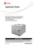
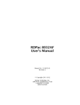
Product Catalog
Split System Condensing Units —RAUJ
Remote Chiller Evaporators
20 - 120 Tons — 50/60 Hz — R-410A
March 2012
SS-PRC030-EN
Introduction
Trane 20 to 120-ton air-cooled condensing units are the leaders in the split system marketplace.
Designed for efficiency, reliability and flexibility, the Trane units have the most advanced design
in the industry.
All 20 to 120-ton units feature the Trane 3-D™ Scroll compressor, solid-state controls and Trane’s
exclusive Packed Stock Plus availability 20 to 60 tons for quick shipment. These innovations make
an already proven product even better!
Trademarks
Trane and the Trane logo are trademarks of Trane in the United States and other countries. All
trademarks referenced in this document are the trademarks of their respective owners.
© 2012 Trane All rights reserved
SS-PRC030-EN
Table of Contents
Introduction . . . . . . . . . . . . . . . . . . . . . . . . . . . . . . . . . . . . . . . . . . . . . . . . . . . . . . . . . . . . 2
Features and Benefits . . . . . . . . . . . . . . . . . . . . . . . . . . . . . . . . . . . . . . . . . . . . . . . . . . . 4
Application Considerations . . . . . . . . . . . . . . . . . . . . . . . . . . . . . . . . . . . . . . . . . . . . . . 6
Selection Procedure . . . . . . . . . . . . . . . . . . . . . . . . . . . . . . . . . . . . . . . . . . . . . . . . . . . . 9
20 to 60-Ton Units . . . . . . . . . . . . . . . . . . . . . . . . . . . . . . . . . . . . . . . . . . . . . . . . 10
80 to 120-Ton Units2
. . . . . . . . . . . . . . . . . . . . . . . . . . . . . . . . . . . . . . . . . . . . . . . . . . . . . . . . . . . 10
Model Number Descriptions . . . . . . . . . . . . . . . . . . . . . . . . . . . . . . . . . . . . . . . . . . . . 10
General Data . . . . . . . . . . . . . . . . . . . . . . . . . . . . . . . . . . . . . . . . . . . . . . . . . . . . . . . . . . 11
Performance Data . . . . . . . . . . . . . . . . . . . . . . . . . . . . . . . . . . . . . . . . . . . . . . . . . . . . . 13
60 Hz Data . . . . . . . . . . . . . . . . . . . . . . . . . . . . . . . . . . . . . . . . . . . . . . . . . . . . . . . 13
50 Hz Data . . . . . . . . . . . . . . . . . . . . . . . . . . . . . . . . . . . . . . . . . . . . . . . . . . . . . . . 17
Controls . . . . . . . . . . . . . . . . . . . . . . . . . . . . . . . . . . . . . . . . . . . . . . . . . . . . . . . . . . . . . . 25
Standard Options 20 to 120-Ton Condensing Units . . . . . . . . . . . . . . . . . . . . 25
Electrical Data . . . . . . . . . . . . . . . . . . . . . . . . . . . . . . . . . . . . . . . . . . . . . . . . . . . . . . . . . 26
Dimensional Data . . . . . . . . . . . . . . . . . . . . . . . . . . . . . . . . . . . . . . . . . . . . . . . . . . . . . . 29
Weights . . . . . . . . . . . . . . . . . . . . . . . . . . . . . . . . . . . . . . . . . . . . . . . . . . . . . . . . . . . . . . 48
Mechanical Specifications . . . . . . . . . . . . . . . . . . . . . . . . . . . . . . . . . . . . . . . . . . . . . . 50
20 to 120-ton Condensing Units . . . . . . . . . . . . . . . . . . . . . . . . . . . . . . . . . . . . . 50
Remote Evaporator Chillers . . . . . . . . . . . . . . . . . . . . . . . . . . . . . . . . . . . . . . . . 51
SS-PRC030-EN
3
Features and Benefits
Trane 3-D Scroll Compressor
Simple Design with 70% Fewer Parts
Fewer parts than an equal capacity reciprocating compressor means significant reliability and
efficiency benefits. The single orbiting scroll eliminates the need for pistons, connecting rods, wrist
pins and valves. Fewer parts lead to increased reliability. Fewer moving parts, less rotating mass
and less internal friction means greater efficiency than reciprocating compressors.
The Trane 3-D Scroll provides important reliability and efficiency benefits. The 3-D Scroll allows the
orbiting scrolls to touch in all three dimensions, forming a completely enclosed compression
chamber which leads to increased efficiency. In addition, the orbiting scrolls only touch with
enough force to create a seal; there is no wear between the scroll plates. The fixed and orbiting
scrolls are made of high strength cast iron which results in less thermal distortion, less leakage, and
higher efficiencies. The most outstanding feature of the 3-D Scroll compressor is the greater
tolerance to slugging tha reciprocating compressors.
Low Torque Variation
The 3-D Scroll compressor has a very smooth
compression cycle; torque variations are only 30
percent of that produced by a reciprocating
compressor. This means that the scroll compressor
imposes very little stress on the motor resulting in
greater reliability. Low torque variation reduces
noise and vibration
Suction Gas Cooled Motor
Compressor motor efficiency and reliability is
further optimized with the latest scroll design. Cool
suction gas keeps the motor cooler for longer life
and better efficiency.
Proven Design Through Testing and Research
With over twenty years of development and testing, Trane 3-D Scroll compressors have undergone
more than 400,000 hours of laboratory testing and field operation. This work combined with over
25 patents makes Trane the worldwide leader in air conditioning scroll compressor technology.
Voltage Power Supply
20 to 120-ton units have four voltage options in 200, 230, 460 and 575.
Passive Manifolding
Trane offers a parallel manifolding scheme that uses no moving mechanical parts. This feature
assures continuous oil return, again providing greater system reliability. And greater reliability
means optimal performance over the life of the unit.
Additional Features
System Control Options
In addition to “no system control” option, Trane offers three system control options on 20-60 ton
units and two system control options on the 80-120 ton units, each using solid- state electronics.
These options allow the unit to be ordered with the controls needed, saving field installation costs.
4
SS-PRC030-EN
Features and Benefits
Coil Frost Protection
Trane offers Frostat™ with the VAV system control option on the 20 to 120-ton units. FROSTAT is
the industry’s most reliable method of coil frost protection and assures that your system will
provide energy efficient comfort at part load conditions.
Remote Chiller Evaporator Option with Field Installation Kit
Allows chilled water to be generated remotely from the condensing section.
The EVP option is controls only and includes unit controller, discharge water temperature sensor
and water freezestat.
Accessory kit includes evaporator, with mounting hardware and insulation, water strainer,
minimum water flow limit switch and evaporator pipe stubs with couplings. Control option must
be selected with accessory kit.
20 to 120-Ton Units
Standard Features
•
•
•
•
•
•
•
•
Trane 3-D™ Scroll compressors
Phase Loss/Reversal/Low Voltage Monitor
Factory-installed Discharge and Liquid Line Service Valves
Passive manifolding for 3-D Scroll compressors
Standard ambient operating range 40°F to 125°F (115°F max ambient for EVP chiller)
Heavy gauge galvanized steel frame
Louvered panels for coil protection
Slate gray air-dry paint finish
Optional Features
•
•
•
•
•
•
•
•
•
•
•
•
•
•
Remote chiller evaporator with field installation kit
Non-fused disconnect (20 to 60-Ton Models)
Low ambient option
Hot gas bypass to the evaporator inlet
Suction service valve
Pressure gauges
Return air sensor
Unit spring isolators
Neoprene-in-shear isolators
cULus approval (not available for 50 Hz)
Packed Stock Plus program (20 to 60-Ton Models)
Extended Compressor Warranty
Corrosion protected condenser coil
Constant volume, VAV, and no controls options on 20 to 60-Ton models, VAV and no controls
options on 80 to 120-Ton Models
Packed Stock Plus
Trane 20 to 60-ton air-cooled condensing units are available through the most flexible packed stock
program in the industry. Trane knows that you want your units on the job site, on time, with the
options you need. Packed Stock Plus provides you with the controls and options you need —
options like hot gas bypass, isolators and refrigerant gauges. You no longer have to settle for a
basic unit requiring many field installed options to meet your job schedule. Now, you can get a
customized unit from the factory in record time. The Packed Stock Plus program provides more
control over unit selection and scheduling than ever before. Trane wants to make it easy for you
to do business with them.
SS-PRC030-EN
5
Application Considerations
Certain application constraints should be considered when sizing, selecting and installing Trane aircooled condensing units. Unit reliability is dependent upon these considerations. Where your
application varies from the guidelines presented, it should be reviewed with the local Trane sales
engineer.
Unit Sizing
Unit capacities are listed in the performance data section. Intentionally oversizing a unit to assure
adequate capacity is not recommended. Erratic system operation and excessive compressor
cycling are often a direct result of an oversized condensing unit. In addition, an oversized unit is
usually more expensive to purchase, install and operate. If oversizing is desired, consider using two
units.
Unit Placement
A base or foundation is not required if the selected unit location is level and strong enough to
support the unit’s operating weight.
Isolation and Sound Emission
The most effective form of isolation is to locate the unit away from any sound sensitive area.
Structurally transmitted sound can be reduced by using spring or rubber isolators. The isolators
are effective in reducing the low frequency sound generated by compressors and, therefore, are
recommended for sound sensitive installations. An acoustical engineer should always be
consulted on critical applications.
For maximum isolation effect, the refrigeration lines and electrical conduit should also be isolated.
Use flexible electrical conduit. State and local codes on sound emissions should always be
considered. Since the environment in which a sound source is located affects sound pressure, unit
placement must be carefully evaluated.
Servicing
Adequate clearance for compressor servicing should be provided. Recommended minimum space
envelopes for servicing are located in the dimensional data section of this catalog and can serve
as guidelines for providing adequate clearance. The minimum space envelopes also allow for
control panel door swing and routine maintenance requirements. Local code requirements may
take precedence.
Unit Location
Unobstructed flow of condenser air is essential for maintaining condensing unit capacity and
operating efficiency. When determining unit placement, careful consideration must be given to
assure proper air flow across the condenser heat transfer surface. Failure to heed these
considerations will result in warm air recirculation and coil air flow starvation.
Warm air recirculation occurs when discharge air from the condenser fans is recycled back at the
condenser coil inlet. Coil starvation occurs when free air flow to the condenser is restricted.
Both warm air recirculation and coil starvation cause reductions in unit efficiency and capacity. In
addition, in more severe cases, nuisance unit shutdowns will result from excessive head pressures.
Accurate estimates of the degree of efficiency and capacity reduction are not possible due to the
unpredictable effect of varying winds.
When hot gas bypass is used, reduced head pressure increases the minimum ambient condition
for proper operation. In addition, wind tends to further reduce head pressure. Therefore, it is
advisable to protect the air-cooled condensing unit from continuous direct winds exceeding 10
miles per hour.
Debris, trash, supplies, etc., should not be allowed to accumulate in the vicinity of the air-cooled
condensing unit. Supply air movement may draw debris between coil fins and cause coil
starvation. Special consideration should be given to units operating in low ambient temperatures.
6
SS-PRC030-EN
Application Considerations
Condenser coils and fan discharge must be kept free of snow and other obstructions to permit
adequate air flow for satisfactory unit operation.
Effect of Altitude on Capacity
Condensing unit capacities given in the performance data tables are at sea level. At elevations
substantially above sea level, the decreased air density will decrease condenser capacity and,
therefore, unit capacity and efficiency. The adjustment factors in Table 4, p. 12 can be applied
directly to the catalog performance data to determine the unit’s adjusted performance.
Ambient Considerations
Start-up and operation at lower ambients requires sufficient head pressure be maintained for
proper expansion valve operation. At higher ambients, excessive head pressure may result.
Standard operating conditions are 40°F to 125°F (115°F max ambient for EVP chiller). With a low
ambient damper, operation down to 0°F is possible. Minimum ambient temperatures are based on
still conditions (winds not exceeding five mph). Greater wind velocities will result in increased
minimum operating ambients. Units with hot gas bypass have a minimum operating ambient
temperature of 10°F. For proper operation outside these recommendations, contact the local Trane
sales office.
Coil Frost Protection
Frostat™ is standard on condensing units when the VAV option is ordered. Frostat™ consists of a
ship-with thermostat for field installation on the suction line. A timer is also factory-installed to
avoid short cycling. Frostat™ cycles the compressor off when the suction line is below 30°F. Refer
to S/S-EB-43 for more detail.
When hot gas valves must be used on 20 to 120-ton units, they can be ordered as a miscellaneous
option. The 20 to 30-ton units require one valve; 40 to 60-ton units also require one valve except
when no system control option is selected; this option requires two valves. The 80 to 120-ton units
require one valve when Supply Air VAV control is selected. Two valves are required on all other 80
to 120-ton control options.
Refrigerant Piping
Special consideration must always be given to oil return. Minimum suction gas velocities must
always be maintained for proper oil return. Utilize Tube Size and Component Selectionapplication
guide SS-APG012-EN for proper system design. For special applications, call Clarksville Product
Support.
Note: Under certain conditions, R-410A refrigerant can present special challenges with piping and
system design. Whenever refrigerant line set lengths approach 150 equivalent feet and/or
design ambient temperature exceeds 115°F, contact your Trane Account Executive to review
application requirements.
Remote Chiller Evaporator
Water Treatment
Using untreated or improperly treated water may result in scaling, erosion, corrosion, and algae
or slime buildup in the heat exchanger that will adversely affect system capacity. Proper water
treatment must be determined locally and depends on the type of system and local water
characteristics. Neither salt nor brackish water is recommended, either will lead to a shortened heat
exchanger life. Trane encourages employment of a qualified water treatment specialist, familiar
with local water conditions, to assist in the establishment of a proper water treatment program.
Water Flow Limits
The minimum and maximum water flow rates are given in Table 2, p. 12. Water flow rates below
the tabulated values will result in laminar flow causing freeze-up problems, scaling, stratification
and poor system control. Flow rates exceeding the maximum listed may result in very high
pressure drop, erosion of the heat exchanger and damage to the water flow switch.
SS-PRC030-EN
7
Application Considerations
Water Temperature Limits
RAUJ with remote EVP chiller performance data is based on a water temperature drop of 10°F. Full
load chilled water temperature drops from 8 to 14°F may be used as long as minimum and
maximum water temperature and minimum and maximum flow rates are not violated. Leaving
water temperatures below 42°F require freeze protection down to 15°F. The maximum water
temperature that can be circulated through the chiller when the unit is not operating is 125°F.
Evaporator damage may result above this temperature.
Short Water Loops
Adequate chilled water system water volume is an important system design parameter because it
provides for stable chilled water temperature control and helps limit unacceptable short cycling of
chiller compressors. Typically, a five-minute water loop circulation time is sufficient to prevent
short water loop issues. Therefore, as a guideline, ensure the volume of water in the chilled water
loop equals or exceeds five times the evaporator flow rate. For systems with a rapidly changing
load profile the amount of volume should be increased.
Note: Water volumes should be calculated as close as possible to maintain constant water flow
through the water loop.
Water Piping
Foreign matter in the chilled water system will increase pressure drop and reduce water flow.
Installation of a properly selected strainer is also necessary to prevent debris larger than 0.039”
from entering the heat exchanger. All building water piping must be thoroughly flushed before
making the final piping connections to the heat exchanger. To reduce heat loss and prevent
condensation, insulation should be applied to piping. Expansion tanks are also generally required
to accommodate chilled water volume changes.
8
SS-PRC030-EN
Selection Procedure
Net capacity curves for the RAUJ condensing units are given in the performance data section.
When matched with a coil curve, the resultant point of intersection will be the system design
balance point. The design operating suction temperature and capacity can then be read directly
from the graph.
Note: It is usually necessary to account for suction and liquid line losses in the performance . The
actual losses are determined by the interconnecting piping.
To plot the DX evaporator performance curve it is only necessary to obtain gross evaporator
capacities for the given entering air conditions and cfm at two different saturated suction
temperatures. The Trane Refrigeration Coil Computer Selection Program can be used to
conveniently provide the necessary evaporator capacity values at the selected suction
temperatures.
Selection Example
The RAUJ 20 to 120-Ton TOPSS™ selection program provides the ability to generate performance
output for pre-selected Trane Modular Climate Changer evaporator coils with the RAUJ
condensing units. To select a condensing unit and evaporator coil not available in the RAUJ
TOPSS™ program, the example below can be used to cross-plot an evaporator coil with known
performance with the RAUJ condensing unit
From the Trane Refrigeration Coil Computer Selection Program:
DX Evap Coil = Model Number DFDB42 - 42" X 60" / 4 Row / 144 FPF - FD/Delta-flo E
Entering Coil Conditions = 80/67 DB/WB and 95°F Ambient - 8500 CFM
Coil Performance @ 38F SST - 406.49 MBh Total
Coil Performance @ 45F SST - 293.09 MBh Total
Balance Point at 95°F Ambient = 370 MBh @ 40.2 SST
Coils are identical fin series and circuiting on both simulations.
Figure 1. 30 Ton condensing unit performance - RAUJ-C30 (60 Hz)
475
Evaporator coil line
406.49MBH
@ 38F SST
Net Capacity(MBH)
425
375
325
293.09MBH
@ 45F SST
275
225
30
32
34
36
38
40
42
44
46
48
50
Saturated Suction(F)
By plotting the two coil performance outputs across the RAUJC30 Net Capacity curve at their
respective total MBH at the defined saturated suction temperatures and ignoring line losses,, we
can see that the condenser/evaporator coil combination, at 95 F ambient, provides 370 MBH Net
Capacity at 40.2 SST.
SS-PRC030-EN
9
Model Number Descriptions
20 to 60-Ton Units1
Digit 17
Digit 13 — Number of Circuits
G = Return Air Sensor
2 = Dual (All 80-120 Ton)
Digit 1 — Unit Type
Digit 18
Digit 14
R = Condensing Unit
J = Corrosion Protected Condenser Coil
B = Hot Gas Bypass Valve
Digit 2 — Condenser
Digit 19
Digit 15
A = Air Cooled
C = Remote Chiller Evaporator & Install
Kit
T = Flow Switch (EVP Control Only)
D = Suction Service Valves
Digit 3 — Airflow
U = Upflow
Digit 4 — Development
Sequence
Digit 20
1 = Spring Isolators
2 = Neoprene Isolators
J= Third
Digits 5,6,7 — Nominal Capacity
C20 = 20 Tons
C25 = 25 Tons
C30 = 30 Tons
C40 = 40 Tons
C50 = 50 Tons
C60 = 60 Tons
80 to 120-Ton Units2
Digit 1 — Unit Type
R = Remote Condensing Unit
E = 200/60/3 XL
D = 415/50/3 XL
F = 230/60/3 XL
4 = 460/60/3 XL
5 = 575/60/3 XL
9 = 380/50/3 XL
Digit 4 — Development
Sequence
B = No System Control
E = Supply Air VAV Control
P = EVP Control
DIGIT 14
B = Hot Gas Bypass Valve
Digit 10 — Design Sequence
(Factory Assigned)
A = First
B = Second
Etc.
Digit 11 — Ambient Control
DIGIT 15
0 = Standard
1 = 0°F (Low Ambient Dampers)
D = Suction Service Valves
Digit 12 — Agency Approval
DIGIT 16
0 = None
3 = cULus (not available for 50 Hz)
F = Pressure Gauges and Piping
1
The service digit for each model number contains
21 digits; all 21 digits must be referenced.
10
C = Remote Chiller Evap & Install Kit
3 = Flow Switch ( EVP Control only)
Digit 8 — Voltage and Start
Characteristics
Digit 9 — System Control
A = Non Fused Unit Disconnect Switch
Digit 19
C80 = 80 Tons
D10 = 100 Tons
D12 = 120 Tons
0 = Standard
1 = 0°F (Low Ambient Dampers)
DIGIT 13
1 = Spring Isolators
Digits 5,6,7 — Nominal Capacity
DIGIT 11 — Ambient Control
0 = None
3 = cULus (not available for 50 Hz)
Digit 18
J = Third
(Factory Assigned)
A = First
B = Second
Etc.
DIGIT 12 — Agency Approval
J = Corrosion Protected Condenser Coil
U = Upflow
E = 200/60/3 XL
F = 230/60/3 XL
4 = 460/60/3 XL
5 = 575/60/3 XL
* = 380/50/3 XL2
* = 415/50/3 XL2
Digit 10 —Design Sequence
Digit 17
A = Air-Cooled
Digit 3 — Airflow
B = No System Control
C = Constant Volume Control
E = Supply Air VAV Control
P = EVP Control
F = Pressure Gauges and Piping
Digit 2 — Condenser
Digit 8 — Voltage and Start
Characteristics
Digit 9 — System Control
Digit 16
2
Contact the local Trane Sales Office for ordering
information regarding 80-120 50Hz models.
SS-PRC030-EN
General Data
Table 1.
General data - 20-120 ton condensing units
Model Number
RAUJ-C20
RAUJ-C25 RAUJ-C30 RAUJ-C40 RAUJ-C50 RAUJ-C60 RAUJ-C80 RAUJ-D10 RAUJ-D12
Compressor Data
Type
Scroll
Scroll
Scroll
Scroll
Scroll
Scroll
Scroll
Scroll
Scroll
10T + 10T
10T +13.5T
15T + 15T
10T + 10T
11.5T +
13.5T
15T + 15T
15T + 15T + 15T + 15T + 20T + 20T +
15T
20T
20T
10T + 10T
11.5T +
13.5T
15T + 15T
15T + 15T + 15T + 15T + 20T + 20T +
15T
20T
20T
Manifolded Sets
Circuit 1
Circuit 2
Unit Capacity Steps
(%)
100-42
100-50
100-75-5025
100-73-4623
100-75-5025
100-83-6650-33-17
100-80-6045-30-15
3/26"/Prop
Direct
3/1.0
20700
3/26:/Prop
Direct
3/1.0
20700
4/26"/Prop
Direct
4/1.0
26790
6/26"/Prop
Direct
6/1.0
36890
6/26"/Prop
Direct
6/1.0
40490
8/26"/Prop
Direct
8/1.0
56490
12/26"/Prop 12/26"/Prop
Direct
Direct
12/1.0
12/1.0
73890
76280
2/42x71
2/42x71
2/42x71
2/59x71
2/51x96
2/51x96
4/59x71
4/51x96
4/64x96
41.4
41.4
41.4
58.2
68.0
68.0
116.4
136.0
170.7
1/240
1/240
1/240
1/240
1/240
1/240
1/240
1/240
1/240
18.7
18.7
18.7
23.5
25.0
25.0
47.1
50.0
62.9
100-50
100-83-6650-33-17
Condenser Fan Data
Qty/Fan Dia. Type
2/26"/Prop
Fan Drive Type
Direct
No. of Motors/HP Ea.
2/1.0
Nominal Total CFM
14600
Condenser Coil Data
Number of Coils/
Size (Inches)
Face Area (Sq. Ft.)
Rows/Fin Per Ft.
Condenser Storage
Capacity (Lbs)(a)
Type
Refrigerant
Microchannel
Data(b)
No. Refrigerant
Circuits
Refrigerant Type
Refrigerant
Operating Charge
(Lbs.)/Unit(c) (d)
1
1
1
2
2
2
2
2
2
R-410A
R-410A
R-410A
R-410A
R-410A
R-410A
R-410A
R-410A
R-410A
11.9
11.8
11.8
22.7
23.4
23.8
57.1
59.1
65.3
Outdoor Air Temperature for Mechanical Cooling
Standard Ambient
Operating Range
(F)(e)
40-125
40-125
40-125
40-125
40-125
40-125
40-125
40-125
40-120
Low Ambient Option
(F)
0
0
0
0
0
0
0
0
0
88.25
60.12
68
88.25
61.12
68
88.25
60.12
68
88.25
88.25
73
113.82
88.25
73
113.82
88.25
73
176.25 in,
88.25
73
227.25 in
88.25
73
227.25 in
88.25
73
Cabinet Dimensions
Length (Inches)
Width (Inches)
Height (Inches)
(a) Condenser storage capacity is given at conditions of 95°F outdoor temperature, and 95% full.
(b) Refer to Refrigerant Piping in the Application Considerations section.
(c) Operating charge is approximate for condensing unit only, and does not include charge for low side or interconnecting lines.
(d) Condensing units are shipped with a nitrogen holding charge only.
(e) Maximum operating ambient for EVP remote chillers is 115°F.
SS-PRC030-EN
11
General Data
Table 2.
General data - 20 - 120 ton remote chillers
RAUJC20
Model Number
RAUJC25
RAUJC30
RAUJC40
RAUJC50
RAUJC60
RAUJC80
RAUJD10
RAUJD12
Shipping weight, lbs
44
84
113
90
135
157
208
292
320
Operating weight, lbs
56
104
142
131
206
244
330
473
520
No. of refrigerant circuits
1
1
1
2
2
2
2
2
2
Water volume, Gal
1.4
2.2
3.3
4.6
7.9
9.7
13.6
20.1
22.2
Chiller refrig charge @ AHRI condition, lbs
0.9
1.5
2.2
3.1
5.3
6.4
9.0
13.3
14.7
Minimum water flow rate, GPM
24
30
36
48
60
72
96
120
144
Maximum water flow rate, GPM
69
89
100
136
176
201
275
346
407
Chiller Water Supply/Return Pipe Size, in
2.0
2.0
2.0
3.0
3.0
3.0
4.0
4.0
4.0
Notes:
1. All heat exchangers are brazed plate.
2. All heat exchangers are single circuit on the water side.
3. Shipping and operating weights are approximate.
4. Refrigerant charge is approximate and for chiller only.
5. Applications with leaving water temperature below 42°F require freeze protection down to 15°F.
6. Maximum chiller operating ambient is 115°F.
Table 3.
EER data - condensing unit only(a)
Net Cap (MBH)
Total Compressor Condenser Fan kW
kW
Each/Total
Control kW
Total Power kW
EER
IEER
RAUJ-C20
266.9
20.6
0.9/1.8
0.4
22.9
11.7
15.1
RAUJ-C25
324.9
23.9
0.9/2.7
0.4
26.9
12.1
15.1
RAUJ-C30
399.4
32.1
0.9/2.7
0.4
35.2
11.4
15.5
RAUJ-C40
545.5
42.4
0.9/3.6
0.7
46.7
11.7
15.4
RAUJ-C50
690.5
53.5
0.9/5.4
0.7
59.6
11.6
15.1
RAUJ-C60
786.6
64.4
0.9/5.4
0.7
70.5
11.2
15.3
RAUJ-C80
1121.0
94.3
0.9/7.2
0.7
102.1
11.0
15.4
RAUJ-D10
1374.0
109.3
0.9/10.8
0.7
120.7
11.4
15.6
RAUJ-D12
1661.0
134.3
0.9/10.8
0.7
145.6
11.3
15.7
Note: Capacity is rated in accordance with AHRI 365 - 95F Ambient, 45F Saturated Suction Temperature
(a) Condensing unit only ratings are in accordance with AHRI standard 365. Full load ratings are at 95°F entering air temperature, and refrigerant conditions
entering the condensing unit of 45°F saturated and 60°F actual temperature. Part load ratings are at 80°F entering air temperature and refrigerant
conditions entering the condensing unit of 50°F saturated suction and 65°F actual temperature.
Table 4.
Altitude correction multiplier for capacity
Altitude (ft.)
2,000
4,000
6,000
8,000
10,000
Condensing Unit Only
0.982
0.960
0.933
0.902
0.866
Condensing Unit / Air Handling Unit Combination
0.983
0.963
0.939
0.911
0.881
Condensing Unit With Evap.
0.986
0.968
0.947
0.921
0.891
12
SS-PRC030-EN
Performance Data
60 Hz Data
Figure 2. 20 Ton condensing unit performance — RAUJ-C20 (60 HZ)
325
300
Net Capacity MBH
275
250
225
200
175
150
30
32
34
36
38
40
42
44
46
48
50
46
48
50
Saturated Suction Temperature (F)
Figure 3. 25 Ton condensing unit performance — RAUJ-C25 (60 HZ)
400
375
350
Net Capacity MBH
325
300
275
250
225
200
175
30
32
34
36
38
40
42
44
Saturated Suction Temperature (F)
SS-PRC030-EN
13
Performance Data
Figure 4. 30 Ton condensing unit performance — RAUJ-C30 (60 HZ)
475
450
425
Net Capacity MBH
400
375
350
325
300
275
250
225
30
32
34
36
38
40
42
44
46
48
50
46
48
50
Saturated Suction Temperature (F)
Figure 5. 40 Ton condensing unit performance — RAUJ-C40 (60 HZ)
650
600
Net Capacity MBH
550
500
450
400
350
300
30
32
34
36
38
40
42
44
Saturated Suction Temperature (F)
14
SS-PRC030-EN
Performance Data
Figure 6. 50 Ton condensing unit performance — RAUJ-C50 (60 HZ)
850
800
750
Net Capacity MBH
700
650
600
550
500
450
400
30
32
34
36
38
40
42
44
46
48
50
46
48
50
Saturated Suction Temperature (F)
Figure 7.
60 Ton condensing unit performance — RAUJ-C60 (60 HZ)
950
900
850
Net Capacity MBH
800
750
700
650
600
550
500
450
30
32
34
36
38
40
42
44
Saturated Suction Temperature (F)
SS-PRC030-EN
15
Performance Data
Figure 8. 80 Ton condensing unit performance — RAUJ-C80 (60 HZ)
1300
1250
1200
1150
1100
Net Capacity MBH
1050
1000
950
900
850
800
750
700
650
30
32
34
36
38
40
42
44
46
48
50
46
48
50
Saturated Suction Temperature (F)
Figure 9. 100 Ton condensing unit performance — RAUJ-D10 (60 HZ)
1600
1500
Net Capacity MBH
1400
1300
1200
1100
1000
900
800
30
32
34
36
38
40
42
44
Saturated Suction Temperature (F)
16
SS-PRC030-EN
Performance Data
Figure 10. 120 Ton condensing unit performance — RAUJ-D12 (60 HZ)
2000
1900
1800
Net Capacity MBH
1700
1600
1500
1400
1300
1200
1100
1000
30
32
34
36
38
40
42
44
46
48
50
46
48
50
Saturated Suction Temperature (F)
50 Hz Data
Figure 11. 20 Ton condensing unit performance — RAUJ-C20 (50 HZ)
275
250
Net Capacity MBH
225
200
175
150
125
30
32
34
36
38
40
42
44
Saturated Suction Temperature (F)
SS-PRC030-EN
17
Performance Data
Figure 12. 25 Ton condensing unit performance — RAUJ-C25 (50 HZ)
325
300
Net Capacity MBH
275
250
225
200
175
150
30
32
34
36
38
40
42
44
46
48
50
46
48
50
Saturated Suction Temperature (F)
Figure 13. 30 Ton condensing unit performance — RAUJ-C30 (50 HZ)
400
375
350
Net Capacity MBH
325
300
275
250
225
200
175
30
32
34
36
38
40
42
44
Saturated Suction Temperature (F)
18
SS-PRC030-EN
Performance Data
Figure 14. 40 Ton condensing unit performance — RAUJ-C40 (50 HZ)
525
500
475
450
Net Capacity MBH
425
400
375
350
325
300
275
250
30
32
34
36
38
40
42
44
46
48
50
46
48
50
Saturated Suction Temperature (F)
Figure 15. 50 Ton condensing unit performance — RAUJ-C50 (50 HZ)
675
625
Net Capacity MBH
575
525
475
425
375
325
30
32
34
36
38
40
42
44
Saturated Suction Temperature (F)
SS-PRC030-EN
19
Performance Data
Figure 16. 60 Ton condensing unit performance — RAUJ-C60 (50 HZ)
775
725
675
Net Capacity MBH
625
575
525
475
425
375
30
32
34
36
38
40
42
44
46
48
50
46
48
50
Saturated Suction Temperature (F)
Figure 17. 80 Ton condensing unit performance — RAUJ-C80 (50 HZ)
1075
1025
975
925
Net Capacity MBH
875
825
775
725
675
625
575
525
30
32
34
36
38
40
42
44
Saturated Suction Temperature (F)
20
SS-PRC030-EN
Performance Data
Figure 18. 100 Ton condensing unit performance — RAUJ-D10 (50 HZ)
1350
1250
1150
Net Capacity MBH
1050
950
850
750
650
30
32
34
36
38
40
42
44
46
48
50
46
48
50
Saturated Suction Temperature (F)
Figure 19. 120 Ton condensing unit performance — RAUJ-D12 (50 HZ)
1650
1550
1450
Net Capacity MBH
1350
1250
1150
1050
950
850
750
30
32
34
36
38
40
42
44
Saturated Suction Temperature (F)
SS-PRC030-EN
21
Performance Data
Table 5.
System performance data — 20-120 Ton RAUJ with remote EVP chiller
Entering Condenser Air Temperature (F)
85
Model
RAUJ C20
RAUJ C25
RAUJ C30
RAUJ C40
RAUJ C50
RAUJ C60
RAUJ C80
22
95
105
115
LWFT(F)
Capacity
Tons
Compr
kW
Capacity
Tons
Compr
kW
Capacity
Tons
Compr
kW
Capacity
Tons
Compr
kW
40
18.8
17.5
17.7
19.4
16.6
21.4
15.4
23.7
42
19.4
17.8
18.3
19.6
17.2
21.7
16.0
23.9
44
20.1
18.0
19.0
19.8
17.8
21.9
16.6
24.1
46
20.8
18.2
19.6
20.0
18.4
22.1
17.1
24.3
48
21.5
18.4
20.2
20.3
19.0
22.3
17.7
24.5
50
22.1
18.6
20.9
20.5
19.6
22.5
18.3
24.7
40
23.3
20.5
21.9
22.7
20.5
25.1
19.0
27.7
42
24.1
20.7
22.7
22.9
21.2
25.3
19.7
28.0
44
24.9
21.0
23.5
23.1
22.0
25.5
20.4
28.2
46
25.8
21.2
24.3
23.4
22.7
25.8
21.1
28.4
48
26.6
21.5
25.1
23.6
23.5
26.0
21.8
28.7
50
27.5
21.7
25.9
23.9
24.2
26.3
22.5
28.9
40
28.4
27.2
26.8
29.8
25.0
32.7
23.3
35.8
42
29.4
27.6
27.7
30.2
25.9
33.1
24.1
36.1
44
30.4
27.9
28.6
30.5
26.8
33.4
25.0
36.5
46
31.4
28.3
29.6
30.9
27.7
33.8
25.8
36.8
48
32.4
28