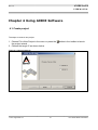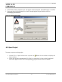
1
[DA1-0032-UM02-011V00-EN]
AXIDE for E8
User Manual
Rev 1.1.0
June 2011
AppoTech Limited
Add: Unit 705-707, 7/F, IC Development Ctr, No. 6, Science Park West Ave. Hong Kong Science Park, Shatin, N.T. HK
Tel: (852) 2607 4090
Fax: (852) 2607 4096 www.appotech.com
Rev 1.1.0
AXIDE for E8
USER MANUAL
Table of Contents
Chapter 1 Introduction .........................................................................6
1.1.Packing List...........................................................................6
1.2.Summary .............................................................................7
1.3.Software ..............................................................................8
1.4.Hardware .............................................................................8
Chapter 2 Installation ...........................................................................9
2.1.System Requirement ..............................................................9
2.2.Installation Process ................................................................9
2.3.Uninstall AXIDE ...................................................................12
Chapter 3 Interface Guide ..................................................................13
3.1.Introduction ........................................................................13
3.2.Interface ............................................................................13
3.2.1.Launch Interface ..........................................................13
3.2.2.Main Interface ..............................................................14
3.2.3.Menu ..........................................................................15
3.3.Toolbar................................................................................19
3.4.Watch Register and Data Ram Window.....................................20
Chapter 4 Using AXIDE Software ........................................................21
4.1.Create project .....................................................................21
4.2.Open Project .......................................................................22
4.3.Project Management ............................................................23
4.3.1.New File ......................................................................23
4.3.2.Add File.......................................................................24
4.3.3.Remove File .................................................................24
4.4.Block Comment / Uncomment ...............................................24
4.5.Display Line Numbers ...........................................................25
4.6.Close All/Save All..................................................................25
Chapter 5 Using Emulator Hardware ..................................................26
Chapter 6 Connect Operation Guide ....................................................28
6.1.Operation Flow Chart ...........................................................28
6.1.1.USB Connection ...........................................................29
6.1.2.Smart Option ...............................................................29
Chapter 7 Debug mode Operation Guide .............................................31
7.1.Connect Emulator (FPGA) Board.............................................31
7.2.Compile Source Code ...........................................................31
© 2011 AppoTech Ltd
3
DA1-0032-UM02-010V00-EN
Rev 1.1.0
AXIDE for E8
USER MANUAL
7.2.1.Assembler ...................................................................31
7.3.Normal (Free) Run ...............................................................32
7.4.Breakpoint Debug ................................................................33
7.5.Single-Step Debug ...............................................................35
7.6.Watch Data .........................................................................35
7.6.1.Watch Registers Window ................................................35
7.6.2.Data RAM Window ........................................................36
Chapter 8 Tutorial ................................................................................37
8.1.Connect and Compile............................................................41
8.1.1.Debug using Emulator Board...........................................41
Appendix I
FAQ .................................................................................43
Appendix II
Compatibility List ..........................................................44
Appendix III
Top Board Configurations ............................................45
Appendix IV
Smart Options ..............................................................48
Appendix V
Revision History .............................................................49
Table of Figure
Figure
Figure
Figure
Figure
Figure
Figure
Figure
Figure
Figure
Figure
Figure
Figure
Figure
Figure
Figure
Figure
Figure
Figure
Figure
Figure
1-1: AXIDE software main interface..................................................7
2-1: Install AXIDE Software.............................................................9
2-2: Select destination..................................................................10
2-3: Click "Next"..........................................................................11
2-4: Wait for installation progress...................................................11
2-5: Click "Close" to finish installation.............................................12
3-1: Welcoming Screen.................................................................13
3-2: Main Interface.......................................................................14
3-3: Toolbar overview...................................................................19
4-1: Choose target IC...................................................................21
4-2: Enter project name................................................................22
4-3: Select project management file................................................23
4-4: Create new file......................................................................24
4-5: Close All/Save All...................................................................25
5-1: Emulator boards....................................................................26
6-1 Operation Flow Chart...............................................................28
7-1: Compile source code..............................................................31
7-2: Debug Toolbar.......................................................................31
7-3: Set breakpoint......................................................................33
7-4: Watch Registers Window.........................................................34
DA1-0032-UM02-010V00-EN
4
© 2011 AppoTech Ltd
Rev 1.1.0
AXIDE for E8
USER MANUAL
Figure
Figure
Figure
Figure
Figure
Figure
Figure
Figure
Figure
Figure
Figure
Figure
Figure
Figure
Figure
Figure
Figure
Figure
Figure
Figure
7-5: Data RAM Window.................................................................35
8-1: Tutorial................................................................................36
8-2: .include................................................................................37
8-3: Set the first breakpoint...........................................................37
8-4: Reach maximum number of breakpoint.....................................37
8-5: Delete All Breakpoint..............................................................38
8-6: Breakpoint in interrupt vector..................................................39
8-7: Breakpoint in delay routine.....................................................39
8-8: Download success message.....................................................40
8-9: Stop at breakpoint.................................................................40
8-10: starting position...................................................................41
8-11: Run to cursor......................................................................41
1: Hardware Configuration Overview...............................................43
2: Power Configuration Jumper (default internal)..............................43
3: External Power Configuration for APG013.....................................44
4: External Power Configuration for APG012.....................................44
5: 5/3.3V Selection (default : 3.3V Internal).....................................44
6: 5/3.3V Selection (5V Internal) (APG012 only)...............................44
7: External RC Configuration..........................................................45
8: Y1/Y2 Configuration..................................................................45
© 2011 AppoTech Ltd
5
DA1-0032-UM02-010V00-EN
Rev 1.1.0
AXIDE for E8
USER MANUAL
Chapter 1
Introduction
1.1. Packing List
A standard AppoTech E8-core microcontroller development suite should have the following
items:
Item
Quantity
Emulator Main Board
x1
Emulator Top Board
x1
Software CD
x1
USB Cable
x1
5V Power Supply
x1
DA1-0032-UM02-010V00-EN
6
© 2011 AppoTech Ltd
Rev 1.1.0
AXIDE for E8
USER MANUAL
1.2. Summary
AppoTech AXIDE for E8 (AXIDE) is a Windows-based Integrated Development Environment
(IDE), including editor, assembler and debugger to interface with the emulator. It supports
project development work based on AppoTech E8-core microcontroller unit (MCU).
•
AXIDE helps to:
•
carry out project management easily;
•
edit and compile source code with a few clicks;
•
debug application with powerful tools like single-stepping and breakpoints.
© 2011 AppoTech Ltd
7
DA1-0032-UM02-010V00-EN
Rev 1.1.0
AXIDE for E8
USER MANUAL
1.3. Software
AXIDE runs on Microsoft Windows operating system. Its main interface is shown below:
Figure 1-1: AXIDE software main interface
It allows users to edit and compile source code with ease. With the emulator hardware,
user can test and debug the application being developed.
1.4. Hardware
The emulator hardware consists of the following parts:
•
Emulator mainboard: for MCU and peripheral emulation
•
Emulator top board: for MCU I/O emulation
DA1-0032-UM02-010V00-EN
8
© 2011 AppoTech Ltd
Rev 1.1.0
AXIDE for E8
USER MANUAL
Chapter 2 Installation
2.1. System Requirement
System requirements for AXIDE are listed below:
•
Computer with 1 GHz or above
•
1 GB memory
•
100MB of available hard disk space
•
CD-ROM or Internet connections
•
Microsoft Windows XP, Windows Vista or Windows 7
•
USB port
2.2. Installation Process
To install AXIDE software to PC:
a. Run setup.msi, then press “NEXT” on the interface:
Figure 2-1: Install AXIDE Software
b.
Select Destination Location
© 2011 AppoTech Ltd
9
DA1-0032-UM02-010V00-EN
Rev 1.1.0
AXIDE for E8
USER MANUAL
Figure 2-2: Select destination
DA1-0032-UM02-010V00-EN
10
© 2011 AppoTech Ltd
Rev 1.1.0
AXIDE for E8
USER MANUAL
c. Click on “Next” button to install
Figure 2-3: Click "Next"
Figure 2-4: Wait for installation progress
d.
Click “Finish” to finish installation
© 2011 AppoTech Ltd
11
DA1-0032-UM02-010V00-EN
Rev 1.1.0
AXIDE for E8
USER MANUAL
Figure 2-5: Click "Close" to finish installation
2.3. Uninstall AXIDE
AXIDE can be uninstalled through Control Panel.
DA1-0032-UM02-010V00-EN
12
© 2011 AppoTech Ltd
Rev 1.1.0
AXIDE for E8
USER MANUAL
Chapter 3 Interface Guide
3.1. Introduction
This chapter will introduce the user interface of AXIDE.
3.2. Interface
3.2.1.
Launch Interface
When AXIDE is running, user can see the interface:
Figure 3-1: Welcoming Screen
© 2011 AppoTech Ltd
13
DA1-0032-UM02-010V00-EN
Rev 1.1.0
AXIDE for E8
USER MANUAL
3.2.2.
Main Interface
Figure 3-2: Main Interface
Menu
Edit Window
Workspace
Window
Status Bar
The Main Interface consists of the following parts:
•
Menu, Toolbar: User can find all the functions in Menu bar, while some functions can be
accessed directly through Toolbar. A pop-up hint will be displayed when mouse cursor is
placed over the button for a moment.
•
Workspace Window: On the left side, where user can see one of the following: Class view,
Project File view, Document view, Variable view (when debugging) and others.
•
Edit Window: On the right side, where user can edit and modify source code.
•
Output Window: On the bottom, where user can see the compiler/connection message, and
output/error information.
•
Status bar: It displays the following information:
a) State of connection, if FPGA is configured or not
b) IC model of the current project
c) PC value
DA1-0032-UM02-010V00-EN
14
© 2011 AppoTech Ltd
Rev 1.1.0
AXIDE for E8
USER MANUAL
3.2.3.
Menu
3.2.3.1.
File Menu
Name
New Project
Shortcut
Ctrl + W
Description
This will bring up the New Project wizard. User can
also press the
New File
Ctrl + N
button to do the same operation.
Create a new empty file in the current project
(source file or header file). User can also press the
button to do the same operation.
Ctrl + O
Open
Open an existing project. User can also press the
button on the toolbar to do the same operation.
Close
-
Close the project.
Add File
-
Add an existing file to the current project.
Remove Files
-
Remove the selected file from the current project.
Ctrl + S
Save the current project file. User can also press
the button on the toolbar to do the same
operation.
-
Save the current file with another name. But the
file with the new name will not be added to the
current project automatically.
-
Save all the currently opened files. User can also
Save ...
Save As ...
Save All
press the
button to do the same operation.
Recent Project
-
Paths of the projects that are opened recently are
recorded here. User can press the specific path to
open the project. At most 5 recent projects can be
saved.
Exit
-
Exit and close AXIDE.
3.2.3.2.
Edit Menu
Name
Undo
Redo
© 2011 AppoTech Ltd
Shortcut
Description
Ctrl + Z
Cancel the last operation. User can press the
button on the toolbar to do the same operation.
Ctrl + Y
Redo the last operation. User can press the button
on the toolbar to do the same operation.
15
DA1-0032-UM02-010V00-EN
Rev 1.1.0
AXIDE for E8
USER MANUAL
Cut
Ctrl + X
Cut the selected text into clipboard.
Copy
Ctrl + C
Copy the selected text into clipboard.
Paste
Ctrl + V
Paste the text in the clipboard to the cursor
position.
Select All
Ctrl + A
Select all text in the current file.
Ctrl + F
Find specific text in the current file.
F4
Jump to previous found text
F3
Jump to next found text
Ctrl + H
Find and replace specified text in the current file
with new text.
Make Selection
Uppercase
Ctrl +
Shift + U
Change the selected text to uppercase letter.
Make Selection
Lowercase
Ctrl + U
Change the selected text to lowercase letter.
Block Comment or
uncomment
Ctrl + Q
Change the text chosen from the current file into
comment or uncomment.
Find
Find Prev
Find Next
Replace
3.2.3.3.
View Menu
Name
Shortcut
Description
Display Line Number
Ctrl + L
Display the line number column on the Edit
window.
Display Bookmark
Margin
-
Display all makers on the left column.
Add a Marker
-
Add maker to the line at the cursor position.
Delete Marker
-
Delete maker to the line at the cursor
position.
Find Next Marker
-
Find the next maker in the current file.
Find Prev Marker
-
Find the previous maker in the current file.
Tool Bar
-
Display/Hide the Toolbar.
Debug Bar
-
Display/Hide the Debug bar.
Status Bar
-
Display/Hide the Status bar.
Fullscreen
-
View in full screen.
ASCII
Ctrl + I
Display/Hide the ASCII Window.
DA1-0032-UM02-010V00-EN
16
© 2011 AppoTech Ltd
Rev 1.1.0
AXIDE for E8
USER MANUAL
Refresh List
-
Refresh data shown on the DataRam
window.
Workspace
-
Display/Hide the Workspace Window
Output
-
Display/Hide the Output Window
Dataram
-
Display/Hide the DataRam Window. In the
DataRam window Users can change the
DATA RAM value and choose the bank of IC.
Register
-
Display/Hide the Watch Registers Window.
In the Watch Registers Window, users can
watch DataRAM, special registers and
change their value.
3.2.3.4.
Setting Menu
Name
Shortcut
Description
Chip Options
-
Select the smart options
Project Options
-
Select the debug output path and include
path
3.2.3.5.
Windows Menu
Name
Shortcut
Description
New Window
-
Open another window for the project
Close
-
Close the present window
Close All
-
Close all the opened windows
Arrange
-
Arrange all minimized windows
Cascade
-
Arrange the windows as overlapping tiles
Tile Vertically
-
Arrange the windows as vertical, nonoverlapping tiles.
Tile Horizontally
-
Arrange the windows as horizontal, nonoverlapping tiles
© 2011 AppoTech Ltd
17
DA1-0032-UM02-010V00-EN
Rev 1.1.0
AXIDE for E8
USER MANUAL
3.2.3.6.
Debug Menu
Name
Compile
Description
Shortcut
F7
Compile the current project. User can do the
same operation by pressing the
on the toolbar.
Rebuild
Crtl+Alt+F7
Clean
button
Compile all the file in the current project.
Old files will all be overwritten.
Delete all the intermediate files
Connect to FPGA
F6
Connect the emulator board with PC.
Run
Ctrl + F5
Start running the compiled program. User
can do the same operation by pressing the
button on the toolbar.
Start Debug
F5
Start running in breakpoint mode. When the
breakpoint is reached, the program will
pause at that point. User can do the same
operation by pressing the
button on the
toolbar.
Pause
Ctrl + Shift
+ Break
Pause the running program. User can do the
same operation by pressing the
button
on the toolbar.
Stop
Shift + F5
Stop the running program and quit the
debug session. User can do the same
operation by pressing the
toolbar.
button on the
Reset
Ctrl + Shift
+ F5
Reset the Program Counter. User can do the
same operation by pressing the
button on
the toolbar.
Step By Step
F11
Start running in single step mode and step
into subroutine. User can do the same
operation by pressing the
toolbar.
button on the
Step over
F10
Start running in single step mode and step
over the subroutine. User can do the same
operation by pressing the
button on the
toolbar.
Run to Cursor
Ctrl + F10
Pause the running program at the cursor
position. User can do the same operation by
pressing the
button on the toolbar.
Breakpoint
F9
Set/Clear the breakpoint on the cursor
DA1-0032-UM02-010V00-EN
18
© 2011 AppoTech Ltd
Rev 1.1.0
AXIDE for E8
USER MANUAL
position. User can do the same operation by
pressing the
button on the toolbar.
Delete All
Breakpoint
Ctrl + Shift
+ F9
Clear all the available breakpoint(s). User
can do the same operation by pressing the
button on the toolbar.
3.3. Toolbar
Figure 3-3: Toolbar overview
Table 3-1: Default Toolbar
Icon
Description
Project Guide: Build a new project.
New File: Open a new blank file
Open Project: Open an existing project.
Save File: Save the current opened file.
Cut: Cut the selection into the Clipboard.
Copy: Copy the selection into the Clipboard.
Paste: Insert the Clipboard contents at cursor.
Undo: Undo the last action.
Redo: Redo the previously action.
Search for next string with reference to textbox
Search for previous string with reference to textbox
Insert a bookmark into program line
Go to the next bookmark
Go to the previous bookmark
Delete the present bookmark
Connect: Connect the emulator board with PC.
Breakpoint: Set/Clear the breakpoint.
Delete All Breakpoint: Clear all the available breakpoint(s).
Compile: Compile Project by assembler.
© 2011 AppoTech Ltd
19
DA1-0032-UM02-010V00-EN
Rev 1.1.0
AXIDE for E8
USER MANUAL
Workspace: Display/Hide the Workspace Window.
Output: Display/Hide the output Window.
Full screen: Display in full screen
ASCII: Display/Hide the ASCII Window.
Table 3-2: Debug Toolbar
Icon
Description
Run: Start running the compiled program.
Start debug: The program will be stopped at the breakpoint when you
press this button.
Pause: When the program is running, press “Pause” and the program will
be stopped immediately.
Stop:Stop the running program and quit the debug session.
Reset: Reset the Program Counter.
Step Into: The program will run just one step (into subroutine) and then
stop when you press this button (Single Step).
Step over: The program will run just one step (over subroutine) and then
stop when you press this button (Single Step).
Run to the cursor: The program will be stopped at the line that cursor
positioned when you press this button.
Data Ram: Display/Hide the Data Ram Window.
Registers: Display/Hide the Watch Registers Window.
3.4. Watch Register and Data Ram Window
During debugging, user can watch the value of special function registers in watch register
and data ram in Data Ram Window. Except for the default registers on the watch list, all
other registers on the list can be dragged to change its position. For details please go to the
section 7.6.1 and 7.6.2.
DA1-0032-UM02-010V00-EN
20
© 2011 AppoTech Ltd
Rev 1.1.0
AXIDE for E8
USER MANUAL
Chapter 4 Using AXIDE Software
4.1. Create project
The steps to create a new project:
1. Choose File->New Project in the menu or press the
the project wizard.
2. Choose the target IC as shown below.
button in the toolbar to launch
Figure 4-1: Choose target IC
© 2011 AppoTech Ltd
21
DA1-0032-UM02-010V00-EN
Rev 1.1.0
AXIDE for E8
USER MANUAL
3. Click ‘Next’ button and then enter the project name and path. Click OK button to confirm.
4. User can also click add sample to load a sample project to get familiar with the
developing environment.
Figure 4-2: Enter project name
APG012A
4.2. Open Project
The steps to open an existing project:
1. Choose File -> Open in the menu or press the
Open window.
button in the toolbar to display the
2. Select the project management file (‘dws’ as extension) in the project’s path and
then click ‘Open’ button. The corresponding project will be shown in AXIDE.
DA1-0032-UM02-010V00-EN
22
© 2011 AppoTech Ltd
Rev 1.1.0
AXIDE for E8
USER MANUAL
Figure 4-3: Select project management file
e
4.3. Project Management
When a new project has been created or an existing project has been opened, user can manage the
project files in the Workspace Window on the left of the AXIDE interface, such as create new file, add file
and remove file. Double-click on one of the files in Workspace Window, and then the file will be opened
in the AXIDE editor.
4.3.1.
New File
The steps to create a new file:
1. Select ‘File->New File’ in the menu or right-click on one of the folders in the Workspace
Window and choose ‘New File’ to launch the New File window.
2. Enter a file name in the ‘File Name’ field. The added file always end with “.asm” and is
considered as source file.
3. Click on ‘OK’ button to finish.
© 2011 AppoTech Ltd
23
DA1-0032-UM02-010V00-EN
Rev 1.1.0
AXIDE for E8
USER MANUAL
Figure 4-4: Create new file
4.3.2.
Add File
This allows users to add an existing file to the current project and the file will be copied to
the corresponding folder. Files with “.ASM” and “.INC” extension will be added to the
Source File folder.
The steps to add file:
1. Select ‘File->Add File’ in the menu or right-click on one of the folders in the
Workspace Window and choose ‘Add File’ to launch the Add File window.
2. Choose the file type (“.ASM” or “.INC”).
3. Choose the file to be added to the project.
4. Click on ‘OK’ button and then the file will be added to the corresponding folder of
the current project.
4.3.3.
Remove File
The steps to remove file:
1. Select ‘File->Remove File’ in the menu or right-click on the file and choose
‘Remove File’ item on the popup menu.
2. AXIDE will ask for confirmation before removal. The file will be removed after user
clicks on ‘OK’ button to confirm.
4.4. Block Comment / Uncomment
Select the lines which user would like to comment or uncomment, then:
1. Right-click on the selection, and select “Block Comment or Uncomment”; or
DA1-0032-UM02-010V00-EN
24
© 2011 AppoTech Ltd
Rev 1.1.0
AXIDE for E8
USER MANUAL
2. Select “Edit->Block Comment or Uncomment”; or
3. Press Ctrl+Q.
4.5. Display Line Numbers
There are three ways to display line numbers:
1. Right-click on the Edit Window, and select “Display Line Numbers”; or
2. Select “View->Display Line Numbers”; or
3. Press Ctrl+L.
4.6. Close All/Save All
User can easily close/save all the opened and edited files with only one click. If user want
to save all the opened files, just right click on the file tab and choose “Save All”. All opened
files will be saved. Under the same principle, the “Close All” button can be used to close all
the opened files at once, without saving.
Figure 4-5: Close All/Save All
© 2011 AppoTech Ltd
25
DA1-0032-UM02-010V00-EN
Rev 1.1.0
AXIDE for E8
USER MANUAL
Chapter 5 Using Emulator Hardware
The emulator hardware package is mainly used for E8-core MCU development and
debugging. Since E8-core MCU only has OTP memory, the emulator board uses FPGA
instead of the target IC for emulating the functions. There are many pins in the board
which are emulating the corresponding pins in the target. These pins can be connected to
the target board for debugging purpose.
Below is a overview of the emulator hardware:
Figure 5-1: Emulator boards
Indicators
USB
Port
DC plug
On/Off
switch
Indicators
Power
Selection
ERC
APG013
MCU pins
XTAL
Crystal 32.768KHz Crystal
1-8M crystal
(1-8MHz)
DA1-0032-UM02-010V00-EN
26
© 2011 AppoTech Ltd
Rev 1.1.0
AXIDE for E8
USER MANUAL
Main Board
Main board is used for E8-core and peripheral emulation, it contains the following
component:
◦ On/Off switch: Emulator power on/ off
◦ DC plug: Connect to 5VDC power supply
◦ USB Port: USB connection to link with PC. Emulator power supply for light target
system loading. The PC USB port should at least provide 500mA current. Note that
it is a type-B female connector.
◦ Indicators:
◦ D1: Power Indicator, located near On/Off switch (Red LED)
◦ D2: Busy, emulator is communicating with PC (Green LED)
◦ D3: Emulator connected (Green LED)
•
D4: Running (Yellow LED)Top board: for MCU I/O emulation
© 2011 AppoTech Ltd
27
DA1-0032-UM02-010V00-EN
Rev 1.1.0
AXIDE for E8
USER MANUAL
Chapter 6 Connect Operation Guide
6.1. Operation Flow Chart
Figure 6-1 Operation Flow Chart
Connect Operation
AXIDE provides communication between PC and emulator board via USB port. The
emulator board communicates with PC using proprietary protocol.
DA1-0032-UM02-010V00-EN
28
© 2011 AppoTech Ltd
Rev 1.1.0
AXIDE for E8
USER MANUAL
6.1.1.
USB Connection
1. Connect emulator board to PC with USB cable. OS will detect the new hardware and
a new USB device will be detected.
2. Open AXIDE. Open an existing project file (*.dws) or create new project (as
explained in detail in Chapter 4) before connect operation.
Click on
button on the toolbar to establish connection. The connection
result will be displayed in the Output Window. The Emulator’s FPGA’s
configuration code will be downloaded.
3. When the emulator board is connected or disconnected, a message will show in
Output Window to notify user. AXIDE will return to its initial state (IDE not
connected) when the emulator board is disconnected. User should check USB
connection to make sure that it is connected properly.
4. The connection status of emulator board will be shown on the status bar of the main
interface.
6.1.2.
Smart Option
Smart Option provides a quick way to configure the hardware and firmware properties for
E8-core MCU.
Example screen of Smart Option of APG012
© 2011 AppoTech Ltd
29
DA1-0032-UM02-010V00-EN
Rev 1.1.0
AXIDE for E8
USER MANUAL
V
Please note that every time the smart option is changed. The user
should press
DA1-0032-UM02-010V00-EN
Restart to apply the change.
30
© 2011 AppoTech Ltd
Rev 1.1.0
AXIDE for E8
USER MANUAL
Chapter 7 Debug mode Operation Guide
7.1. Connect Emulator (FPGA) Board
User can connect the emulator board at any time. Once the board is connected and
recognized by the computer. AXIDE will automatically connect to the board, and the
message “IDE Attached!” will be displayed. While disconnecting the board from the
computer , the message of “IDE Detached“ will be brought up.
7.2. Compile Source Code
7.2.1.
Assembler
The steps to compile an assembler project:
1. Open the project to be compiled, and then select ‘Program->Compile’ in the menu or click on
button in the toolbar to compile the project with the assembler. Before compiling the
project, AXIDE will automatically save the current file first. Assembler result will be displayed
in Output Window.
2. When program is assembled successfully, AXIDE will transfer the objective file to the target
IC and display ‘Start transfer IRAM data …’ in the Output Window. If transfer is successful,
‘Transfer finished.’ will be displayed. If transfer fails, ‘Fatal Error: Unknown Command, Debug
stop.’ will be displayed. When program fails to assemble, error reports will be displayed in the
Output Window. You can double-click on the error message to find out where the error
happens (marked by an arrow).
© 2011 AppoTech Ltd
31
DA1-0032-UM02-010V00-EN
Rev 1.1.0
AXIDE for E8
USER MANUAL
Figure 7-1: Compile source code
7.3. Normal (Free) Run
Figure 7-2: Debug Toolbar
When program is compiled and transferred successfully, the debug toolbar will appear on
the screen. To start to free run the program ignoring breakpoints, click on
button in the
toolbar to run the program in the target IC. The message ‘Program is running …’ will be
displayed in the Output Window.
User can click on
button in the toolbar when the program is running and then the
program will pause. All the status of the program will be displayed, including the SFR and
SRAM status. A message will show in the Output Window at which line the program is
paused.
User can watch the value of registers and Data RAM in order to check program status. Click
DA1-0032-UM02-010V00-EN
32
© 2011 AppoTech Ltd
Rev 1.1.0
AXIDE for E8
USER MANUAL
on
button in the toolbar to continue to run program again at the paused line.
Click on
button in the toolbar to stop the running program.
7.4. Breakpoint Debug
There are 4 ways to set a breakpoint for debugging:
•
Place cursor at the line to set a breakpoint. Then, right-click and select ‘Breakpoints’ item on the
pop-up menu.
•
Place cursor at the line to set a breakpoint and then select ‘Debug->Breakpoint’ from the menu.
•
Place cursor at the line to set a breakpoint and then click on
•
Press F9 when the cursor is placed on the target line.
button in the toolbar.
When a breakpoint is set, a red dot at the left of the line will indicate that there is a
breakpoint. The start debugging
icon will become available as long as at least one
breakpoint is defined. Press the icon and the program will execute until it hits the first
breakpoint. Then the program will stop and display all its status before the termination of
execution.
© 2011 AppoTech Ltd
33
DA1-0032-UM02-010V00-EN
Rev 1.1.0
AXIDE for E8
USER MANUAL
Figure 7-3: Set breakpoint
When program is compiled and transferred successfully, user can set a breakpoint at a
certain line and then click on
button in the toolbar. The program will stop at the
breakpoint and the breakpoint’s PC value will be displayed in the Output Window. A green
arrow will indicate the line that the program reaches. At this point, click on
button in the
toolbar, the Watch Registers Window will show and user can watch the value of registers in
order to know about the program status (refer to section 6.6). User can change location of
breakpoint and click on
button to continue to debug after the program pauses. If no
breakpoint is set or the breakpoint location cannot be reached, there will be two
possibilities after
•
button is clicked on.
If the program is running in invalid address area, the program will be unable to
response correctly. In this case, user can click on
•
button to stop.
If the program is running in valid address area, user can click on
button to
pause. At this point, user can change location of breakpoint and all data returning
will be valid.
DA1-0032-UM02-010V00-EN
34
© 2011 AppoTech Ltd
Rev 1.1.0
AXIDE for E8
USER MANUAL
7.5. Single-Step Debug
When program stops at a breakpoint or pauses at a certain line, click on
button or
button in the toolbar to run in Single step. The program will stop again after one instruction
is executed. The PC value will be displayed in the Output Window and the register values
will be displayed in the Watch Registers Window. The difference between the
button and
the
button is that:
will single-step into subroutine;
will single-step over
subroutine and will stop at instruction after finish calling the subroutine.
7.6. Watch Data
When program stops at a certain line, user can open Watch Registers Window, Data RAM
Window, or IRAM Window to view the values of special function registers, Data RAM or
IRAM.
7.6.1.
Watch Registers Window
Figure 7-4: Watch Registers Window
SFR Name
SFR Vallue
Selection Bar
Select ‘Project->Register’ in the menu or click on
button in the toolbar to open the
Watch Registers Window, where user can watch the values of special function registers
(SFR) and Data RAM by adding them to the register list.
There are 2 ways to add registers to the register list:
•
Select the SFR from the drop-down list of the Combo Box in Watch Register Window and then
click ‘Add’ button.
•
Enter the name or address of the SFR directly in the Combo Box and then click ‘Add’ button.
© 2011 AppoTech Ltd
35
DA1-0032-UM02-010V00-EN
Rev 1.1.0
AXIDE for E8
USER MANUAL
7.6.2.
Data RAM Window
Select ‘Project->Dataram’ in the menu or click on
button in the toolbar to open the
Data RAM Window. Dataram window can only be opened when the code had been
successfully compiled and downloaded to the emulator board.
Figure 7-5: Data RAM Window
DA1-0032-UM02-010V00-EN
36
© 2011 AppoTech Ltd
Rev 1.1.0
AXIDE for E8
USER MANUAL
Chapter 8 Tutorial
Here is a quick tutorial introducing user to experience the powerful multiple breakpoints,
multiple sources feature. To begin this tutorial, the user can browse for the folder “tutorial”
in the installation CD come with the package.
The tutorial project include several source file “*.asm” and “*.inc”:
File Name
Description
MAIN.asm
The Main program
INIT.asm
Main program initialization routine
DELAY.asm
Delay routine
ISR.asm
Interrupt vector routine
APG013.inc
Defines location of control
registers, ROM size, RAM start
address and size
Figure 8-1: Tutorial
© 2011 AppoTech Ltd
37
DA1-0032-UM02-010V00-EN
Rev 1.1.0
AXIDE for E8
USER MANUAL
Now click and open MAIN.asm, it can be noted that besides the program instruction lines,
there are several lines that begin with “#include ….” as shown below. This allows the
MAIN.asm to include other asm files containing other routines, such as DELAY function.
Figure 8-2: .include
Now try to put a breakpoint on line 28 of the MAIN.asm, as shown below.
Figure 8-3: Set the first breakpoint
Note that AX1KIDE supports a total of 14 breakpoints. This is especially handy when user
needs to debug a program that call many routines – so there are a lot of possible paths for
the program outcome. In this situation, the program can still be traced with breakpoints set
at all possible paths.
Continue to add breakpoints until the limit is reached.
Figure 8-4: Reach maximum number of breakpoint
DA1-0032-UM02-010V00-EN
38
© 2011 AppoTech Ltd
Rev 1.1.0
AXIDE for E8
USER MANUAL
Now the program code is full of breakpoints, but not all are needed, AX1KIDE offers a quick
way to remove all breakpoints at once. Click Debug on the Menu, then choose Delete All
Breakpoint.
Figure 8-5: Delete All Breakpoint
© 2011 AppoTech Ltd
39
DA1-0032-UM02-010V00-EN
Rev 1.1.0
AXIDE for E8
USER MANUAL
And also set another breakpoint on line 20 of ISR.asm (2nd line of ISR):
Remarks: Setting breakpoint at the first line of ISR is not supported
Figure 8-6: Breakpoint in interrupt vector
Set breakpoint in the delay routine on line 11 of DELAY.asm
Figure 8-7: Breakpoint in delay routine
DA1-0032-UM02-010V00-EN
40
© 2011 AppoTech Ltd
Rev 1.1.0
AXIDE for E8
USER MANUAL
8.1. Connect and Compile
With AXIDE, it is easy to connect and compile the program. Just run the program code on
the emulator board, which allow the application to interact with outside using board I/O to
read/write data.
8.1.1.
Debug using Emulator Board
Debug the application simply by pressing Connect
and then Compile
. Make sure you
stay at the MAIN.asm before connect and compile, otherwise, error will occur. Note that in
the status bar if the connect and compile action are successful, the following message
should appear:
Figure 8-8: Download success message
Then click start debugging icon, or simply press F5 to click start debugging. The PC should
stop at the first breakpoint, which is located in the delay routine. Click start debugging
again, until the interrupt fires and the program counter stop at the interrupt routine.
Figure 8-9: Stop at breakpoint
© 2011 AppoTech Ltd
41
DA1-0032-UM02-010V00-EN
Rev 1.1.0
AXIDE for E8
USER MANUAL
Click Restart
, and the program counter will go back to the starting position.
Figure 8-10: starting position
Now go to MAIN.asm, right click on line 41 and choose “Run to cursor”, the line will stop at
that position. Press the button Step Into
, and notice the Program Counter change. Step
Into until the Program Counter reach line 11 of DELAY.asm.
Now go back to MAIN.asm, right click on line 41 and choose “Run to cursor”. Press Step
Over
, notice the Program Counter change again and this time it stops at line 42 of
MAIN.asm.
Figure 8-11: Run to cursor
DA1-0032-UM02-010V00-EN
42
© 2011 AppoTech Ltd
Rev 1.1.0
AXIDE for E8
USER MANUAL
Appendix I
FAQ
This section covers the problems from the basic usage of the AXIDE.
Q: What should I do when the application fails to compile?
A: This may happen when the main source file is not set.
1. Select and open the appropriate main source file from the workspace window.
2. Press the Compile button to start the compilation.
Q: What should I do when the Debug button is disabled?
A: This may happen when no breakpoint is set.
1. Select and open the source file from the workspace window.
2. In the edit window, select an appropriate line and press the Breakpoint button to set
breakpoint.
3. Press Connect to FPGA button to configure the FPGA, and then press Compile button
to download the output binary to the emulator board.
4. When download finishes, the Debug button will be enabled.
Q: Why the IDE only compile one file, even when I include other source file into the
project?
A: Link function is not supported by AXIDE. Use “include file” method if the project contains
more than one source file. The tutorial chapter gives an example of how to include multiple
source files.
Q: When hitting the “SLEEP”, why the target cannot continue to run by pressing the Run
button?
A: This is the feature of the emulator in order to implement real chip behavior. The target
will go into sleep mode when hitting the “SLEEP” instruction, unless triggered by I/O input
or watchdog timer timeout. The IDE still allows user to pause or run to read the register
values.
Q: Why the register values did not update when I modify the values during “SLEEP”?
A: This is the limitation of the emulator.
© 2011 AppoTech Ltd
43
DA1-0032-UM02-010V00-EN
Rev 1.1.0
AXIDE for E8
USER MANUAL
Appendix II
Compatibility List
This section covers the MCU and hardware compatible with AXIDE for E8.
Supported MCU:
Item name
APG012
APG013
Supported Emulator hardware:
Item name
Version
Emulator Mainboard
TA1-0003-PCB01-010ES,
TA1-0003-PCB01-010MP
Top Board
TA1-0032-PCB01-010ES,
TA1-0032-PCB02-010MP
DA1-0032-UM02-010V00-EN
44
© 2011 AppoTech Ltd
Rev 1.1.0
AXIDE for E8
USER MANUAL
Appendix III
Top Board Configurations
1. Top Board Configuration
Top board is used for MCU I/O emulation. There are some setting which are configurable
through setting jumpers at the left hand side of the top board. These setting allow user to
dictate the voltage output of the MCU MCU IO pins.
Figure 1: Hardware Configuration Overview
P4
P7
P5
GND
P8
2. Power Configuration (P7)
The default configuration of VDD/VDDA is connect to internal power supply of 3.3V as
shown below. I/O can output logic level at both 5V and 3.3V selectable from 5/3.3V
selection jumper while APG013 can only use 3.3V logic.
It is also possible to customize the voltage output level by connecting an external voltage
supply at P4. P4 can accept voltage range from 2.5V to 5V.
Figure 2: Power Configuration Jumper (default internal)
© 2011 AppoTech Ltd
V_ADJ
V_ADJ
VDD
VDDA
5/3.3V
+3. 3V
45
DA1-0032-UM02-010V00-EN
Rev 1.1.0
AXIDE for E8
USER MANUAL
Figure 3: External Power Configuration for APG013
V_ADJ
V_ADJ
VDD
VDDA
5/3.3V
+3. 3V
P4 Voltage Range:
+2.5-+3.3V
Figure 4: External Power Configuration for APG012
V_ADJ
V_ADJ
VDD
VDDA
5/3.3V
+3. 3V
P4 Voltage Range:
+2.5-+5V
3. 5/3.3V Selection (P8)
When Power Configuration Jumper is set to use internal power supply. There are two
possible option for internal voltage configuration. One is 3.3V which is the default setting in
which both APG012 and APG013 can operate. Another is 5V which should only be used with
APG012 only.
V
Please notes that while the emulator is capable of emulating APG013
at 5V, it is not recommended. The real APG013 IC are not designed
to operate at 5V.
Figure 5: 5/3.3V Selection (default : 3.3V Internal)
EX 33
5/3.3V
5V
Figure 6: 5/3.3V Selection (5V Internal) (APG012 only)
46
EX 33
5/3.3V
5V
DA1-0032-UM02-010V00-EN
© 2011 AppoTech Ltd
Rev 1.1.0
AXIDE for E8
USER MANUAL
4. External Crystal Input
APG013 emulator allow three sources of external crystal input:
1. ERC: External RC can be connected through R39 and C28
2. XTAL: Crystal with frequency from 1-8MHz can be connected to Y2
3. 32.768KHz: 32.768KHz crystal can be connected through Y1
Figure 7: External RC Configuration
R39
C28
Figure 8: Y1/Y2 Configuration
dfdf
© 2011 AppoTech Ltd
OR
47
DA1-0032-UM02-010V00-EN
Rev 1.1.0
AXIDE for E8
USER MANUAL
Appendix IV
Smart Options
This section covers the configurations of the Smart Options.
1. APG012
Name
Description
RSTB
Reset pin option
RDPORT
Read port option
PB4CLKO
PB4 clock output selection
WDTSEL
Watchdog reset behavior selection
PORSEL
Power-on reset delay time selection
PCHSEL
Program counter high selection
CLKSEL
Type of clock selection
WDTCEN
Enable or disable watchdog timer
RCSEL
RC frequency selection
CLKDIV
CLK division selection
ID Space
User space for storing user information
2. APG013
Name
Description
RSTB
Reset pin option
RDPORT
Read port option
PB4CLKO
PB4 clock output selection
WDTSEL
Watchdog reset behavior selection
PORSEL
Power-on reset delay time selection
PCHSEL
Program counter high selection
CLKSEL
Type of clock selection
WDTCEN
Enable or disable watchdog timer
RCSEL
RC frequency selection
CLKDIV
CLK division selection
ID Space
User space for storing user information
Appendix IV
Compatibility List
DA1-0032-UM02-010V00-EN
48
© 2011 AppoTech Ltd
Rev 1.1.0
AXIDE for E8
USER MANUAL
Appendix V
Date
Version
Revision History
Comment
Revised by
2011-0509
0.1.0
Preliminary Release
Rimsky Cheng
2011-0621
1.1.0
Added support to APG012
Added feature to preserve smart options
across sessions
Updated Appendix III: Added smart
options description for APG012
Updated Appendix IV: Added APG012
Zack Pang
The information in this document is believed to be accurate in all respects at the time of publication but is
subject to change without notice. AppoTech assumes no responsibility for errors and omissions, and disclaims
responsibility for any consequences resulting from the use of information included herein. Additionally,
AppoTech assumes no responsibility for the functioning of undescribed features or parameters. AppoTech
reserves the right to make changes without further notice. AppoTech makes no warranty, representation or
guarantee regarding the suitability of its products for any particular purpose, nor does AppoTech assume any
liability arising out of the application or use of any product or circuit, and specifically disclaims any and all
liability, including without limitation consequential or incidental damages. AppoTech products are not designed,
intended, or authorized for use in applications intended to support or sustain life, or for any other application in
which the failure of the AppoTech product could create a situation where personal injury or death may occur.
Should Buyer purchase or use AppoTech products for any such unintended or unauthorized application, Buyer
shall indemnify and hold AppoTech harmless against all claims and damages.
In case of any questions or comments about this documentation, please feel free to contact AppoTech at
[email protected].
© 2011 AppoTech Ltd
49
DA1-0032-UM02-010V00-EN