1
1990 TOYOTA
CELICA
THROTTLE
1)
STWITH
1.6 L ENGINE
LEVER ADAPTOR
250-4204
.
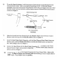
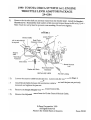
Remove the throttle shaft nut and lock washer from the throttle shaft. Install the Bracket Throttle Lever. Reinstall the lock washer and hex nut, and torque the nut to 84 in-lb (7 ft-lb).
Note: Start the nut by hand to prevent cross-threading. Do not over tighten.
,
,..
FI{';
1/8. of cable MUST
be exposed
\
URE
1
Loosen
Bracket-Cable
This
Nut
Bead Chain
Connector Cove,\
I
"
\
,
~~
-I
\.~
Bead Chain
Connector
1'-
-~
-~..
~
/
I
I
"
~
Snap-In
Adaptor
,
I
.ir'-
!
~
i..-~~j
/..
.:'~Jml
\..4li
!T ( .
~
~
;
I
Chain
---w
.~
11 }1 ~ )
II "
II
'.'
II
Ii
--
\ .",
Washer-#10 Plain
Bead Chain Eyelet
Connector
,
INST
3'
\ ~\\\\\}
A--"\
11'
Bead
-
/
ONLY
,\~r1
! r RR~
2)
PACKAG~
ALLEQ
VIEW
"
Bracket- Throttle
,\
Lever
Pin-Self Locking
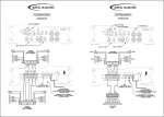
Loosen the accerator cable bracket jam nut. Loosen only the nut shown in Figure I.
.~,..ii8I
--""
Install Bracket-Cable between the accelerator cable bracket and the jam nut previously
loosened and retighten the jam nut.
4)
Remove the Snap-In Adaptor from the Cruise Control Kit.
5)
Remove the Adjustable Sleeve from the Cruise Control Module Cable.
@ Dana Corporation 1990
All Rights Reserved
Printed in the United States of America
Form #2310
6)
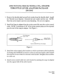
To use the Snap-In Adaptor, it will be necessary to form threads on the end of the Cruise
Control Module Cable. This is accomplished by placing the 1/4" -20 Nut and Washer
Assembly on the end of the Cruise Control Module Cable With your fingers, then use a 7/16"
box end wrench and turn clockwise, until the desired amount of threads have been formed
as shown in Figure 2.
,~
Before Threading Cable
01143
,
f
"""
NuLand
\
\
Cruise
Washer
~;embly
114 -20
\
/
Control
Module
Cable
I
~/
~
01150
After Threading Cable
FIGURE
2
7)
After the threads have been formed screw the Snap-In Adaptor onto the Cruise Control
Module Cable and snap into the BracKet-Cable as shown i~ Figure 1.
8)
Install the Bead Chain Eyelet Connector, with the Bead Chain and Bead Chain Connector
Cover in place, and the Wash~- #10 Plain to the Bracket- Throttle Lever and install the
Pin- Self Locking as shown in Figure 1.
9)
Connect the Bead Chain with the Bead Chain Connector (Double Ended)j to the Cruise
Control Module Cable, with no slack in Bead Chain, and install a Bead Chain Connector
Cover as shown in Figure 1.
10)
Be sure that the throttle is not being held open by the Cruise Control Cable. Adjust cable
by releasing Snap-in Adaptor from Bracket-Cable and threading in or out to adjust cable to
proper length. Snap Adaptor b~ck into-jli--a&et.