1
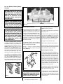
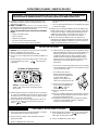
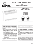
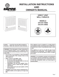
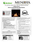
HOMEOWNER'S CARE AND
OPERATION INSTRUCTIONS
B-VENT
GHC/GRD-5500 SERIES
B-VENTED GAS FIREPLACES
P/N 725,029M REV. C 07/2004
MODELS
GRD-5500 SHOWN
Millivolt
Models
Electronic
Models
GHC-5500N
GHC-5500P
GRD-5500N
GRD-5500P
GHC-5500NE-2
GHC-5500PE-2
GRD-5500NE-2
GRD-5500PE-2
RETAIN THESE INSTRUCTIONS
FOR FUTURE REFERENCE
WH Report No. J20046562
WARNING: IF THE INFORMATION IN THIS MANUAL
IS NOT FOLLOWED EXACTLY, A FIRE OR EXPLOSION MAY RESULT CAUSING PROPERTY DAMAGE, PERSONAL INJURY OR LOSS OF LIFE.
FOR YOUR SAFETY: Do not store or use gasoline
or other flammable vapors or liquids in the vicinity of this or any other appliance.
FOR YOUR SAFETY: What to do if you smell gas:
AVERTISSEMENT: ASSUREZ-VOUS DE BIEN SUIVRE
LES INSTRUCTIONS DONNÉ DANS CETTE NOTICE POUR
RÉDUIRE AU MINIMUM LE RISQUE D'INCENDIE OU
POUR ÉVITER TOUT DOMMAGE MATÉRIEL, TOUTE
BLESSURE OU LA MORT.
POUR VOTRE SÉCURITÉ: Ne pas entreposer ni utiliser
d'essence ni d'autre vaperurs ou liquides inflammables
dans le voisinage de cet appareil ou de tout autre
appareil.
POUR VOTRE SÉCURITÉ: Que faire si vous sentez une
odeur de gaz:
DO NOT light any appliance.
DO NOT touch any electrical switches.
DO NOT use any phone in your building.
Immediately call your gas supplier from a
neighbor’s phone.
Follow your gas suppliers instructions.
• If your gas supplier cannot be reached, call the
fire department.
• Ne pas tenter d'allumer d'appareil.
• Ne touchez à aucun interrupteur. Ne pas vous servir
des téléphones se trouvant dans le batiment où
vous vous trouvez.
• Evacuez la piéce, le bâtiment ou la zone.
• Appeflez immédiatement votre fournisseur de gaz
depuis un voisin. Suivez les instructions du
fournisseur.
• Si vous ne pouvez rejoindre le fournisseur de gaz,
appelez le service dos incendies.
Installation and service must be performed by a
qualified installer, service agency or the gas
supplier.
L'installation et service doit être exécuté par un qualifié
installer, agence de service ou le fournisseur de gaz.
•
•
•
•
NOTE: DIAGRAMS & ILLUSTRATIONS NOT TO SCALE.
1
CONGRATULATIONS!
In selecting this Superior B-vented gas appliance you have chosen the finest and most
dependable fireplace to be found anywhere. A beautiful, prestigious, alternative to a
wood burning fireplace. Welcome to a Family of tens of thousands of satisfied Superior
Fireplace Owners.
Please read and carefully follow all of the instructions found in this manual. Please pay
special attention to the safety instructions provided in this manual. The Homeowner's
Care and Operation Instructions included here will assure that you have many years of
dependable and enjoyable service from your Superior product.
TABLE OF CONTENTS
Introduction ..................................... page
General Information ......................... page
2
2
Operation/Care of Your Appliance .... page
Gas Controls/Control
3
Compartment Access ...................... page
Combustion Air Controls ................. page
3
4
Maintenance .................................... page
Manual Limit Switch ........................ page
5
5
Burner Adjustments ......................... page
Flame Appearance and Sooting ..... page
5
5
Adjustment ................................... page
Maintenance Schedule ..................... page
5
6
Log and Rockwool Placement ......... page
Millivolt Appliance Checkout ............ page
7
7
Electronic Appliance Checkout ......... page
Wiring Diagrams .............................. page
7
9
Warranty .......................................... page
Product Reference Information ....... page
9
9
Replacement Parts .......................... page 9
Lighting Instructions – Millivolt ....... page 10
Lighting Instructions – Electronic .... page 12
Troubleshooting Guide – Millivolt ..... page 14
Troubleshooting Guide – Electronic .. page 15
Accessory Components ................... page 16
Replacement Parts List ..................... page 17
INTRODUCTION
The millivolt appliances are designed to operate on either natural or propane gas. A millivolt
gas control valve with piezo ignition system
provides safe, efficient operation.
The electronic appliances are designed to operate on either natural or propane gas. An
electronic intermittent pilot system provides
safe, efficient operation. External electrical
power is required to operate these units.
2
These appliances comply with National Safety
Standards and are tested and listed by Warnock
Hersey (Report No. J20046562) to ANSI ANSI
Z21.50 - 2000 (in Canada, CSA 2.22 - 2000),
and CAN/CGA-2.17-M91 in both USA and
Canada, as vented gas fireplaces.
Installation must conform to local codes. In
the absence of local codes, installation must
comply with the current National Fuel Gas
Code, ANSI Z223.1 (NFPA 54). (In Canada, the
current CAN/CGA B149 installation code.) Electrical wiring must comply with local codes. In
the absence of local codes, installation must
be in accordance with the National Electrical
Code, NFPA 70 - (latest edition). (In Canada,
the current CSA C22.1 Canadian Electric Code.)
DO NOT ATTEMPT TO ALTER OR MODIFY
THE CONSTRUCTION OF THE APPLIANCE OR
ITS COMPONENTS. ANY MODIFICATION OR
ALTERATION MAY VOID THE WARRANTY,
CERTIFICATION AND LISTINGS OF THIS UNIT.
Provide adequate clearances around air openings and adequate accessibility clearance for
service and proper operation. Never obstruct
the front openings of the appliance.
Due to high temperatures the appliance should
be located out of traffic and away from furniture and draperies. Locate furniture and window coverings accordingly.
WARNING: THESE FIREPLACES ARE
VENTED DECORATIVE GAS APPLIANCES.
DO NOT BURN WOOD OR OTHER MATERIAL IN THESE APPLIANCES.
These appliances are designed to operate on
natural or propane gas only. The use of
other fuels or combination of fuels will degrade the performance of this system and
may be dangerous.
For elevations of 0-2000 ft. (0-610 m.) the
GHC/GRD-5500 input is 24,000 BTU/HR for
both natural and propane gases.
Table 1 shows the units' factory-installed
gas orifice size for installations at elevations
of 0-2000 feet (0-610 meters).
GHC
GRD
Series
5500
WARNING: IMPROPER INSTALLATION,
ADJUSTMENT, ALTERATION, SERVICE
OR MAINTENANCE CAN CAUSE INJURY
OR PROPERTY DAMAGE. REFER TO THIS
MANUAL. FOR ASSISTANCE OR ADDITIONAL INFORMATION CONSULT A
QUALIFIED INSTALLER, SERVICE
AGENCY OR THE GAS SUPPLIER.
GENERAL INFORMATION
Note: Installation and repair should be performed by a qualified service person. The appliance should be inspected annually by a qualified professional service technician. More frequent inspections and cleanings may be required due to excessive lint from carpeting,
bedding material, etc. It is imperative that the
control compartment, burners and circulating
air passage ways of the appliance be kept clean.
S'assurer que le brùleur et le compartiment
des commandes sont propres. Voir les instructions d'installation et d'utilisation qui
accompagnent l'apareil.
NOTE: DIAGRAMS & ILLUSTRATIONS NOT TO SCALE.
Orifice size
Nat.
Prop.
#43
#54
Elevation
Feet
(meters)
0-2000
(0-610)
Table 1
Nominal operating pressures for the manifold
side of the gas control system are; 3.5 inches
water column (6.54 MmHg) for natural gas
models and 10 inches water column (18.69
MmHg) for propane gas models.
Do not use these appliances if any part has
been under water. Immediately call a qualified,
professional service technician to inspect the
appliance and to replace any parts of the
control system and any gas control which
have been under water.
Ne pas se servir de cet appareil s'il a été plongé
dans l'eau, complètement ou en partie. Appeler
un technicien qualifié pour inspecter l'appareil et
remplacer toute partie du système de contrôle et
toute commande qui ont été plongés dans l'lau.
Millivolt appliances may be fitted at time of
manufacture with either a Robertshaw millivolt
gas control valve or Robertshaw electronic gas
control valve. Both valves have been tested
with and approved for use with these appliances and are listed accordingly.
A ¹⁄₈" NPT test gage connection is provided on
either gas control valve adjacent to the outlet to
the main burner.
Minimum inlet gas pressure to the appliance is
4.5 inches water column (8.55 MmHg) for
natural gas and 11 inches water column (20.55
MmHg) for propane for the purpose of input
adjustment.
Maximum inlet gas supply pressure to the
appliance is 10.5 inches water column (19.95
MmHg) for natural gas and 13.0 inches water
column (24.25 MmHg) for propane.
The appliance must be isolated from the gas
supply piping system (by closing its individual
manual shut-off valve) during any pressure testing of the gas supply piping system at test
pressures equal to or less than ¹⁄₂ psig (3.5 kPa).
The appliance and its individual shut-off valve
must be disconnected from the gas supply
piping system during any pressure testing of
that system at pressures in excess of ¹⁄₂ psig
(3.5 kPa).
These appliances must not be connected to a
chimney or flue serving a separate solid fuel
burning appliance.
WARNING: FAILURE TO COMPLY WITH
THE INSTALLATION AND OPERATING INSTRUCTIONS PROVIDED IN THIS DOCUMENT WILL RESULT IN AN IMPROPERLY
INSTALLED AND OPERATING APPLIANCE, VOIDING ITS WARRANTY. ANY
CHANGE TO THIS APPLIANCE AND/OR
ITS OPERATING CONTROLS IS DANGEROUS. IMPROPER INSTALLATION OR USE
OF THIS APPLIANCE CAN CAUSE SERIOUS INJURY OR DEATH FORM FIRE,
BURNS, EXPLOSION OR CARBON MONOXIDE POISONING.
Carbon Monoxide Poisoning: Early signs of
carbon monoxide poisoning are similar to
the flu with headaches, dizziness and/or
nausea. If you have these signs, obtain fresh
air immediately. Turn off the gas supply to
the appliance and have it serviced by a
qualified professional, as it may not be operating correctly.
WARNING: B-VENT APPLIANCES ARE NOT
DESIGNED TO OPERATE IN NEGATIVELY
PRESSURED ENVIRONMENTS (PRESSURE
WITHIN THE HOME IS LESS THAN PRESSURES OUTSIDE). SIGNIFICANT NEGATIVELY PRESSURED ENVIRONMENTS
CAUSED BY WEATHER, HOME DESIGN,
OR OTHER DEVICES MAY IMPACT THE
OPERATION OF THESE APPLIANCES.
NEGATIVE PRESSURES MAY RESULT IN
POOR FLAME APPEARANCE, SOOTING,
DAMAGE TO PROPERTY AND/OR SEVERE
PERSONAL INJURY. DO NOT OPERATE
THESE APPLIANCES IN NEGATIVELY PRESSURED ENVIRONMENTS.
WARNING: CHILDREN AND ADULTS
SHOULD BE ALERTED TO THE HAZARDS
OF HIGH SURFACE TEMPERATURES. USE
CAUTION AROUND THE APPLIANCE TO
AVOID BURNS OR CLOTHING IGNITION.
YOUNG CHILDREN SHOULD BE CAREFULLY SUPERVISED WHEN THEY ARE IN
THE SAME ROOM AS THE APPLIANCE.
WARNING: DO NOT PLACE CLOTHING
OR OTHER FLAMMABLE MATERIALS
ON OR NEAR THIS APPLIANCE.
AVERTISSEMENT: SURVEILLER LES
ENFANTS. GARDER LES VÊTEMENTS,
LES MEUBLES, L'ESSENCE OU AUTRES
LIQUIDES À VAPEUR INFLAMMABLES
LIN DE L'APPAREIL.
Piezo
Ignitor
Millivolt
Gas Valve
Figure 1
Control Compartment Access - GRD-5500
Units
The lower control compartment access panel
has been designed to cover the control compartment from view. Lighting instructions are
displayed on the back side of the cover for easy
reference. To attach the panel to the appliance,
hook both ends of the panel over the two
brackets mounted on each side of the front
combustion opening. The cover should hang
from the brackets with the flared edge at the
bottom allowing for a small air gap between the
cover and the appliance. To remove, lift the
panel and pull away from the unit.
Control Compartment Access - GHC-5500 Units
The GHC lower control compartment access is
provided by removing the three louvers .
To remove the louvers, pull them straight out
from the unit. To replace, tilt each of them with
the top edge over the top of each peg and snap
the lower edge to lock in place. See Figure 2.
OPERATION AND CARE OF YOUR
APPLIANCE
Appliance operation must be controlled through
a remotely located wall switch (factory-supplied). Separate switches may provide independent control for the remote controlled fireplace operation (optional equipment).
Gas Controls/Control Compartment
Access
See Figure 1 for the location of the gas control
valve and piezo ignitor (millivolt units).
NOTE: DIAGRAMS & ILLUSTRATIONS NOT TO SCALE.
Louver
Pegs
Louvers
Figure 2
GHC-5500
3
O
N
O
F
F
ON/OFF SWITCH
CONTROL KNOB
AVERTISSEMENT: POUR UTILISATION
UNIQUEMENT AVEC LES PORTES EN
VERRE CERTIFIÊES AVEC L'APPAREIL.
P
C
M
MILLIVOLT GAS CONTROL VALVE
Figure 3
Operation of millivolt and electronic gas control systems are different. Before lighting and
operating your appliance determine if you have
a millivolt or electronic appliance. Millivolt
appliances will be fitted with the gas control
valve shown in Figure 3. Appliances with
electronic systems will be fitted with the electronic valve shown in Figure 4. Familiarize
yourself with the differing controls for the
valve your appliance uses.
Millivolt Appliance Lighting
To light millivolt appliances refer to the detailed lighting instructions found in both English and French on pages 10 and 11 of these
instructions respectively. Appliance lighting
instructions may also be found on the pullout label located near the gas valve in the
control compartment. Refer to Figure 1 for
the piezo ignitor location used with your
appliance.
ELECTRONIC GAS CONTROL VALVE
Figure 4
2. Keep lower control compartment clean by
vacuuming or brushing at least twice a year.
More frequent cleaning may be required due
to excessive lint from carpeting, bedding materials, etc. It is important that control compartments, burners and circulating air passageways of the appliance be kept clean.
3. Always turn off gas to the pilot (millivolt
appliances) before cleaning. Before re-lighting,
refer to the lighting instructions in this manual.
Appliance lighting instructions may also be
found on the pull-out label located near the
gas valve in the control compartment.
4. Always keep the appliance area clear and
free from combustible materials, gasoline and
other flammable liquids.
5. Remember, Millivolt appliances have a continuous burning pilot flame. Exercise caution
when using products with combustible vapors.
Your appliance comes supplied with remote
wall switch or can be used with an optional
remote control kit. The appliance main burner
may be turned on and off with the wall switch
or remote control.
6. Clean the optional glass doors only when
necessary. Wipe surface with clean, dampened, soft cloth. Follow with dry, soft towel as
desired. Take care not to scratch the glass
surface.
Electronic Appliance Lighting
To light electronic appliances refer to the detailed lighting instructions found in both English and French on pages 12 and 13 of these
instructions respectively. Appliance lighting
instructions may also be found on the pullout label located near the gas valve in the
control compartment.
WARNING: DO NOT USE ABRASIVE
CLEANERS. NEVER CLEAN THE GLASS
WHEN IT IS HOT.
Your appliance comes supplied with remote
wall switch or can be used with an optional
remote control kit. The appliance main burner
may be turned on and off with the wall switch
or remote control.
1. When lit for the first time, this appliance will
emit a slight odor for an hour or two. This is
due to the “burn-in” of internal paints and
lubricants used in the manufacturing process.
Glass Doors
Fully Open or
Fully Closed
(Bi-Fold Doors)
Figure 5
Outside Combustion Air Controls
Appliances may be installed with an outside
(make-up air) vent system that is designed to
provide the appliance with outside make-up
air for combustion when in operation. The
shut-off lever for the outside air system is
standard on all appliances but should not be
operated if the complete system is not installed. Refer to Figure 6 for GHC/GRD-5500
series units.
The hand operated shut-off lever is located in the
left side of the fireplace opening behind the
screen. To open, pull all the way. The outside air
damper should be fully open when the fireplace
is in use and completely closed when the fireplace is not being used. This will prevent outside
cold air from entering the dwelling.
WARNING: DO NOT OPERATE THE
SHUTOFF LEVER UNLESS A COMPLETE
OUTSIDE AIR VENT SYSTEM HAS BEEN
INSTALLED WITH YOUR APPLIANCE.
CAUTION: DO NOT ATTEMPT TO TOUCH THE
DOORS WITH YOUR HANDS WHILE THE FIREPLACE IS IN USE. ALWAYS USE DOOR
HANDLES. DOORS WILL BECOME VERY HOT
WHEN FIREPLACE IS IN USE.
WARNING: FIREPLACES EQUIPPED
WITH OPTIONAL ACCESSORY DOORS
SHOULD BE OPERATED ONLY WITH THE
DOORS FULLY OPEN OR FULLY CLOSED
(FIGURE 5 ). THIS APPLIANCE MAY
ONLY BE FITTED WITH DOORS CERTIFIED FOR USE WITH THE APPLIANCE.
Combustion Air Control Lever
Combustion Air Control Lever
on GHC/GRD-5500 Series Units
Figure 6
4
NOTE: DIAGRAMS & ILLUSTRATIONS NOT TO SCALE.
Maintenance
Manual Reset Limit Switch
The appliance and venting system should be
thoroughly inspected before initial use and at
least annually by a qualified service technician. Proper maintenance and use will require
more frequent, less extensive inspections and
servicing by the homeowner.
Generally, annual inspections should be performed by a qualified service technician. More
frequent periodic inspections and cleanings
should be performed by the homeowner. Any
discrepancies discovered by the homeowner
should result in a call to a qualified service
technician to effect the repair or correction.
Lintel
Extention
Refer to the maintenance schedule for maintenance tasks, procedures, periodicity and by
whom they should be performed.
IMPORTANT: TURN OFF GAS AND ANY ELECTRICAL POWER BEFORE SERVICING THE
APPLIANCE.
MANUALLY-RESET BLOCKED FLUE SAFETY
SWITCH
This appliance is equipped with a manuallyreset blocked flue safety switch. Refer to
Figure 7 for its location. If during appliance
operation, the flame goes out (independently
of the burner on/off wall switch), it may be due
to the operation of this safety limit switch.
First allow the appliance to cool. Then reset
the safety switch by pushing the red reset
button on the back of the switch.
CAUTION: THE ELECTRONIC APPLIANCE
SHOULD BE TURNED OFF BEFORE REMOVING THE LIMIT SWITCH.
To access the safety limit switch reset button,
remove the two screws. Pull out limit switch
with low voltage wires attached, push the reset
button, then reinstall the limit switch. At this
time turn the electronic appliance back on.
The appliance should then relight and remain
lit. If this does not occur, turn off the appliance and call a qualified service technician.
Burner Adjustments
Flame Appearance and Sooting
Firebox Wrapper
Limit Switch Screws
Figure 7
If the air shutter opening is too small sooting
may develop. Sooting is indicated by black
puffs developing at the tips of very long orange
flames. Sooting results in black deposits forming on the logs, appliance inside surfaces and
on exterior surfaces adjacent to the vent termination. Sooting is caused by incomplete combustion in the flames and a lack of combustion
air entering the air shutter opening.
Adjustment
To adjust the flame, position the air shutter to
the nominal setting (Figure 8 ). Allow the
burner to operate for at least 30 minutes.
Observe the flame continuously. If it appears
weak or sooty as previously described, adjust
the air shutter open or closed until desired
effect is achieved.
To achieve a warm yellow to orange flame with
an orange body that does not soot, the shutter
opening must be adjusted between these two
extremes.
Orifice
Air Shutter
No smoke or soot should be present. Reposition the log set if the flames impinge on any of
them.
Adjusting
Set Screw
If sooting conditions exist, the air shutter
opening on the main burner can be adjusted.
Normally, the more offsets in the vent system,
the greater the need for the air shutter to be
opened further.
WARNING: AIR SHUTTER ADJUSTMENT
SHOULD ONLY BE PERFORMED BY A
QUALIFIED PROFESSIONAL SERVICE
TECHNICIAN.
Burner Tube
Nominal Air Shutter Settings:
Natural Gas - Closed
Propane Gas - 1/6 in. (1.59 mm) Open
Figure 8
Proper flame appearance is a matter of taste.
Generally most people prefer the warm glow of
a yellow to orange flame. Appliances operated
with air shutter openings that are too large, or
with long vertical vent runs, will exhibit flames
that are blue and transparent. These weak, blue
and transparent flames are termed anemic.
NOTE: DIAGRAMS & ILLUSTRATIONS NOT TO SCALE.
5
Maintenance Schedule
Annually (Before the onset of the Burning Season)
Maintenance Task
Accomplishing Person
Procedure
Inspecting/Cleaning Burner, Logs
and Controls
Qualified Service Technician
Inspect valve and ensure it is properly operating. Check piping for leaks. Vacuum the
control compartment, fireplace logs and burner
area.
Check Flame Patterns and Flame Height
Qualified Service Technician
Refer to Figure 10 on page 7 and verify the
flame pattern and height displayed by the
appliance conforms to the picture.
Inspecting/Cleaning Pilot and Burner
Qualified Service Technician
Refer to Figure 11 on page 7. Remove any
surface build-up on pilot and burner assembly. Wipe the pilot nozzles, ignitor/flame rod
and hood. Ensure the pilot flame engulfs the
flame sensor as shown.
Checking Vent System
Qualified Service Technician
Inspect the vent system at the top and at the
base (within the firebox) for signs of blockage
or obstruction. Look for any signs of dislocation of the vent components.
Appliance Checkout
Qualified Service Technician
Perform the appropriate appliance checkout
procedure detailed in this manual.
Replacing Rockwool Ember Materials
Homeowner/Qualified Services Technician
Remove old ember materials and vacuum the
rockwool placement area. Place new rockwool
as described in this document.
Periodically (After the Burning Season)
Maintenance Task
6
Accomplishing Person
Procedure
Cleaning Firebox Interior
Homeowner
Carefully remove logs, Rockwool and volcanic
stone if used. Vacuum out interior of the
firebox. Clean firebox walls and log grate.
Replace logs, Rockwool and volcanic stone as
detailed in this manual.
Check Flame Patterns and Flame Height
Homeowner
Refer to Figure 10 on page 7 and verify the
flame pattern and height displayed by the
appliance conforms to the picture. Flames
must not impinge on the logs.
Checking Vent System
Homeowner
Inspect the vent system at the top and at the
base (within the firebox) for signs of blockage
or obstruction. Look for any signs of dislocation of the vent components.
Cleaning Optional Glass Doors
Homeowner
Clean as necessary following the directions
provided in this manual. DO NOT TOUCH OR
ATTEMPT TO CLEAN DOORS WHILE THEY
ARE HOT.
NOTE: DIAGRAMS & ILLUSTRATIONS NOT TO SCALE.
Logs and Rockwool (Glowing Embers)
Placement
WARNING: LOGS GET VERY HOT AND
WILL REMAIN HOT UP TO ONE HOUR
AFTER GAS SUPPLY IS TURNED OFF.
HANDLE ONLY WHEN LOGS ARE COOL.
TURN OFF ALL ELECTRICITY TO THE
APPLIANCE BEFORE YOU INSTALL
GRATE AND LOGS.
WARNING: THIS APPLIANCE IS NOT
MEANT TO BURN WOOD. ANY ATTEMPT
TO DO SO COULD CAUSE IRREPARABLE
DAMAGE TO YOUR APPLIANCE AND
PROVE HAZARDOUS TO YOUR SAFETY.
Rockwool
Figure 10
Millivolt Appliance Checkout
WARNING: THE SIZE AND POSITION OF
THE LOG SET WAS ENGINEERED TO GIVE
YOUR APPLIANCE A SAFE, RELIABLE
AND ATTRACTIVE FLAME PATTERN. ANY
ATTEMPT TO USE A DIFFERENT LOG SET
IN THE FIREPLACE WILL VOID THE WARRANTY AND WILL RESULT IN INCOMPLETE COMBUSTION, SOOTING, AND
POOR FLAME QUALITY.
The gas control system on these appliances is
a millivolt standing pilot type. It consists of a
pilot burner, a piezo ignitor, a gas control valve,
a burner assembly and an ON/OFF wall switch.
A temperature limit switch is wired in series
with the millivolt wall switch and gas control
valve. If a higher than normal temperature is
sensed due to a blocked vent or prolonged
downdraft, the limit switch will open and cause
the burner to shut off.
The logs are packaged within the firebox.
The bag of rockwool is in the lower control
compartment. Remove the rockwool from
the packaging and tear into dime size pieces
(Figure 9). Spread across the burner in front
of the front log. See Figure 10. Do not use
more than is necessary to cover the burner.
When properly positioned, the rockwool will
unevenly cover approximately 85% of the
front of the burner with no appreciable gaps.
The pilot flame should be steady, not lifting or
floating. Flame should be blue in color with
traces of orange at the outer edge.
1. Remove the pilot adjustment cap located on
the main gas valve.
2. Adjust the pilot screw to provide properly
sized pilot flame (Figure 10 ). Turn counter
clockwise to enlarge pilot flame and clockwise
to reduce the pilot flame. DO NOT attempt to
adjust pilot flame more than one half turn.
3. Replace the pilot adjustment cap.
The top ³⁄₈" (9 mm) at the pilot generator
(thermopile) should be engulfed in the pilot
flame (Figure 11).
Replace logs if removed for pilot inspection.
To light the burner; rotate the gas valve control
knob counterclockwise to the “ON” positionand
then turn “ON” the remote wall switch.
Electronic Appliance Checkout
³⁄₈" (10 mm)
These appliances are equipped with a beautifully
crafted four (4) piece ceramic fiber log set. The
logs, shown in Figure 12 on page 8, are to be
positioned precisely as shown. Any modification to the to the lay of these logs may result in
sooting, property damage and injury or death.
Figure 11
Figure 9
If the pilot flame pattern is not as shown in
Figure 11, adjust it as follows:
WARNING: PILOT FLAME PATTERN
ADJUSTMENT SHOULD ONLY BE PERFORMED BY A QUALIFIED PROFESSIONAL SERVICE TECHNICIAN.
NOTE: DIAGRAMS & ILLUSTRATIONS NOT TO SCALE.
The gas control system on these appliances is
an electronic low voltage gas control valve with
an intermittent ignitor. It consists of a low
voltage gas control valve, an intermittent ignition system, an electronic control module, transformer and a burner assembly. A temperature
limit switch is wired in series with the gas
control valve. If a higher than normal temperature is sensed, due to a blocked vent or prolonged downdraft, the limit switch will open
and cause the burner to shut off.
The pilot flame should be steady, not lifting or
floating. Flame should be blue in color with
traces of orange at the outer edge.
To light the burner, push the gas control lever
in and toward the left to the “ON” position.
Turn ‘ON’ the remote wall switch. Ensure the
ignitor lights the pilot. The pilot flame should
engulf the ignitor.
7
Carefully position and center the fiber logs
onto the burner grate with the longer log in
front and the shorter log all the way to the
back of the fireplace. Place the two (2) smaller
fiber logs across the two (2) lower logs in the
manner illustrated (Figures 12 ).
a
CAUTION: THESE CERAMIC FIBER LOGS
MUST BE HANDLED CAREFULLY. THEY
WILL STAND UP INDEFINITELY TO EXTREME TEMPERATURES. HOWEVER, THEY
ARE VERY FRAGILE AND ARE SUSCEPTIBLE TO CRUSHING AND/OR BREAKAGE
IF HANDLED ROUGHLY.
No. DESCRIPTION
b
c
d
Figure 12
8
NOTE: DIAGRAMS & ILLUSTRATIONS NOT TO SCALE.
Part No.
Log Set (Complete)
13M3701
a.
Log, Rear, Bottom
13M3001
b.
Log, Front, Bottom
13M3101
c.
Log, Top, Left
13M3201
d.
Log, Top, Right
13M3301
GHC/GRD-5500
LOG PLACEMENT
WIRING DIAGRAMS
Wiring diagrams are provided here for reference purposes only. This information is also
provided on schematics attached directly to
the appliance on a pullout panel located within
the control compartment.
GHC-5500
Robertshaw Ignition Control Equipped
GHC/GRD-5500
Robertshaw Ignition Control Equipped
1. If any of the original wire as supplied must be replaced,
1. it must be replaced with Type AWM 105°C – 18 GA. wire.
2. 120V, 60Hz – Less than 3 amps.
1. If any of the original wire as supplied must be replaced,
1. it must be replaced with Type AWM 105°C – 18 GA. wire.
2. 120V, 60Hz – Less than 3 amps.
ON/OFF SW
LIMIT SW.
120 VAC
LIMIT SW
ON/OFF SW
WALL BLOWER SW
120 VAC
BK
BK
BK
24V
LOW
VOLTAGE
CAUTION: LABEL ALL WIRES PRIOR TO DISCONNECTION WHEN SERVICING CONTROLS.
WIRING ERRORS CAN CAUSE IMPROPER AND
DANGEROUS APPLIANCE OPERATION.
W
BK
GND
Green
Ground
Screw
GHC Series Only
W
24V
LOW
VOLTAGE
Appliance
Ground
Screw
GND
BK
Opt
Blower
Green
Ground
Screw
W
R
R
BK
W
BK
Ignitor
Junction Box
BK
W
TH
TP
BL
R
BL
BL
BK
BK
PRODUCT REFERENCE INFORMATION
We recommend that you record the following
important information about your fireplace.
Please contact your dealer for any questions
or concerns. For the number of your nearest
dealer, please call 800-731-8101
REPLACEMENT PARTS
PV
IGN
Factory Wired
Electronic System Wiring
(Without Forced Air Kit)
Normally, all parts should be ordered through
your distributor or dealer. Parts will be shipped
at prevailing prices at time of order.
GHC/GRD-5500
(Honeywell Ignition Module Equipped)
1. If any of the original wire as supplied must be replaced,
1. it must be replaced with Type AWM 105°C – 18 GA. wire.
2. 120V, 60Hz – Less than 3 amps.
When ordering repair parts, always give the
following information:
1. The model number of the appliance.
2. The serial number of the appliance.
3. The part number.
4. The description of the part.
5. The quantity required.
6. The installation date of the appliance.
Field Wired
Electronic System Wiring
(With Forced Air Kit)
LIMIT SW
ON/OFF SW
NEU. W
BK
120 VAC. BK
GND
24V
Low Voltage
Green
Ground
Screw
R
W
If you encounter any problems or have any
questions concerning the installation or application of this system, please contact your distributor, or LHP directly:
BK
LHP
1110 West Taft Avenue
Orange, CA 92865
Ignitor
Junction Box
BK
BK
W
R
A complete parts list is found at the end of this
manual. Use only parts supplied from the
manufacturer.
TR
Ignition Control
Field Wired
Transf.
120 V.
Gas Valve
M
C
P
G
Your gas appliance is covered by a limited
twenty year warranty. You will find a copy of
the warranty accompanying this manual.
Please read the warranty to be familiar with its
coverage.
Retain this manual. File it with your other
documents for future reference.
BL
GND
TH
MV
IGN
TR
GND
TH
MV
Ignition Control
Factory Wired
WARRANTY
24 V
W
BK
PV/MV
TH
W
PV/MV
TP
24 V
BK
Thermopile
ON/OFF Wall
Switch
Transf.
120 V.
Gas Valve
M
C
P
PV
Limit
Switch
Gas Valve
C
P
GND
M
BK
W
Transf.
120 V.
GND
R
Ignitor
Junction Box
24 V
BK
BL
BL
W
The Date On Which Your Fireplace Was Installed __________________________
The Type of Gas Your Fireplace Uses ___________________________________
Your Dealer's Name _________________________________________________
NOTE: DIAGRAMS & ILLUSTRATIONS NOT TO SCALE.
SPARK
TH-W
(OPT.)
24V
GND
24V
GND
(Burner)
PV
MV
Your Fireplace's Serial Number ________________________________________
PV/MV
Your Fireplace's Model Number _______________________________________
Ignition Control
Factory Wired
Field Wired
Electronic System Wiring
(Without Forced Air Kit)
9
LIGHTING INSTRUCTIONS – MILLIVOLT GAS VALVE
FOR YOUR SAFETY READ BEFORE LIGHTING
WARNING: IF YOU DO NOT FOLLOW THESE INSTRUCTIONS EXACTLY, A FIRE OR EXPLOSION
MAY RESULT CAUSING PROPERTY DAMAGE, PERSONAL INJURY OR LOSS OF LIFE.
A. This appliance has a pilot which must be lighted with a piezo
ignitor. When lighting the pilot, follow these instructions
exactly.
B. BEFORE OPERATING smell all around the appliance area for
gas. Be sure to smell next to the floor because some gas is
heavier than air and will settle on the floor.
WHAT TO DO IF YOU SMELL GAS
•
•
•
•
Extinguish any open flame.
Open windows.
Do not light any appliance.
Do not touch any electrical switches.
• Do not use any phone in your building.
• Immediately call your gas supplier from a neighbor’s phone.
• If your gas supplier cannot be reached, call the fire department.
C. Use only your hand to push in or turn the gas control knob.
Never use tools. If the knob will not push in or turn by hand,
do not try to repair it, call a qualified service technician. Force
or attempted repair may result in a fire or an explosion.
D. Do not use this appliance if any part has been under water.
Immediately call a qualified service technician to inspect the
appliance and to replace any part of the control system and
any gas control which has been under water.
LIGHTING INSTRUCTIONS
1. STOP! Read the safety information above on this page.
2. Access the lower control compartment.
3. Turn remote wall switch to “OFF.”
6. Wait five (5) minutes to clear out any gas. If you then smell gas,
STOP! Follow “B” in the safety information above on this page. If you
do not smell gas, go to the next step.
7. Push in gas control knob slightly and turn counterclockwise
to “PILOT.”
4. Verify main line shut-off valve is open.
5. Push in gas control knob slightly and turn clockwise
to “OFF.”
8. Push in control knob all the way and hold in. Immediately light the
pilot by triggering the spark ignitor (pushing the button) until pilot
lights. Continue to hold the control knob in for about 1 ¹⁄₂ minutes
after the pilot is lit. Release knob and it will pop back up. Pilot should
remain lit. If it goes out, repeat steps 5 through 8.
CONTROL KNOB
• If knob does not pop up when released,
stop and immediately call your service
technician or gas supplier.
• If pilot will not stay lit after several
tries, turn the control knob to “OFF”
and call your service technician or
gas supplier.
9. Turn gas control knob counterclockwise
to “ON.”
Note: Knob cannot be turned from “PILOT” to “OFF”
unless the knob is pushed in slightly. Do not force.
10. Close lower control compartment.
TO TURN OFF GAS TO APPLIANCE
1. Turn remote wall switch “OFF.” The pilot will remain lit for
normal service.
4. Depress gas control knob slightly and turn clockwise
to “OFF.” Do not force.
2. For complete shutdown, turn remote wall switch to “OFF.”
5. Close lower control compartment.
3. Access the lower control compartment.
10
NOTE: DIAGRAMS & ILLUSTRATIONS NOT TO SCALE.
INSTRUCTIONS D’ALLUMAGE – VANNE GAZ MILLIVOLT
POUR VOTRE SÉCURITÉ, LISEZ CES INSTRUCTIONS AVANT L’ALLUMAGE
AVERTISSEMENT : SI VOUS NE SUIVEZ PAS CES INSTRUCTIONS À LA LETTRE, IL POURRAIT S’EN SUIVRE UN INCENDIE OU UNE
EXPLOSION CAUSANT DES DOMMAGES MATÉRIELS, DES BLESSURES CORPORELLES OU MÊME DES PERTES DE VIE.
A. Cet appareil est muni d’une veilleuse qui doit être allumée avec un
allumeur piézo-électrique. Lorsque vous allumez la veilleuse, suivre
exactement ces instructions.
B. AVANT L’ALLUMAGE: Assurez-vous que vous ne détectez aucune
odeur de gaz autour de l’apareil ainsi que près du sol; certains gaz, étant
plus lourds que l’air, descendent au niveau du sol.
VOICI CE QUE VOUS DEVEZ FAIRE SI VOUS DÉCELEZ UNE ODEUR
DE GAZ:
• Éteignez toute flamme visible.
• Ouvrez les fenêtres.
• N’allumez aucun appareil.
• Ne touchez à aucun commutateur électrique.
• Ne vous servez d’aucun téléphone dans votre édifice.
• Appelez immédiatement votre compagnie de gaz en utilisant le téléphone
du voisin.
• S’il vous est impossible de contacter votre compagnie de gaz, appelez
le service des incendies.
C. N’utilisez que votre main pour manipuler le bouton de réglage du gaz.
N’utilisez jamais d’outils. Si le bouton refuse de tourner ou de bouger,
n’essayez pas de le réparer. Communiquez immédiatement avec un
technicien de service qualifié. Toute tentative pour le forcer ou le
réparer, risquerait de provoquer un incendie ou une explosion.
D. Ne vous servez pas de cet appareil si l’un de ses éléments a été
immergé dans l’eau. Appelez immédiatement un technicien compétent
pour faire inspecter l’appareil et remplacer toute pièce du système de
réglage ou commande du gaz qui a été sous l’eau.
INSTRUCTIONS D'ALLUMAGE
1.
2.
3.
4.
ARRÊTEZ! Lisez les consignes de sécurité au verso de cette plaque.
Ouvrez le compartiment de contrôle du bas.
Tournez l’interrupteur mural à la position d’arrêt “OFF”.
Assurez-vous que la soupape d’arrêt de la canalisation principale est
ouverte.
5. Enfoncez légèrement le bouton de réglage du gaz et tournez-le dans
le sens des aiguilles d’une montre
jusqu’à la position
d’arrêt “OFF”.
Le Bouton de Réglage du Gaz
8. Enfoncez le bouton de réglage jusqu’au fond et gardez-le enfoncé.
Allumez immédiatement la veilleuse en déclenchant l’allume-gaz à
étincelle (en poussant le bouton) jusqu’à ce que la veilleuse
s’enflamme. Continuez de tenir le bouton de réglage enfoncé
pendant environ 90 secondes après l’allumage de la veilleuse.
Relâchez le bouton et il sortira subitement. La veilleuse devrait
rester allumée. Si elle s’éteint, répétez les étapes 5 à 8
inclusivement.
• Si le bouton ne sort pas automatiquement après avoir été relâché,
arrêtez immédiatement et téléphonez à votre technicien de service
ou à votre fournisseur de gaz.
• Si la veilleuse refuse de rester
allumée après plusieurs tentatives,
tournez le bouton de réglage jusqu’à
sa position d’arrêt “OFF” et
téléphonez à votre technicien de
service ou à votre fournisseur de gaz.
Remarque: Il est impossible de tourner le bouton de
“PILOT” à “OFF” à moins qu’il ne soit légèrement enfoncé.
Ne le forcez pas.
6. Attendez cinq (5) minutes pour l’evacuation du gaz. Si vous décelez
une odeur de gaz, ARRÊTEZ ! Retournez au point “B” des consignes
de sécurité au verso de cette plaque. Si vous ne remarquez aucune
odeur de gaz, passez à l’étape suivante.
7. Enfoncez légèrement le bouton de réglage du gaz et tournez-le en
sens inverse des aiguilles d’une montre jusqu’à la position de
veilleuse
“PILOT”.
9. Tournez le bouton de réglage du gaz
en sens inverse des aiguilles d’une
montre
jusqu’à sa
position de marche “ON”.
10. Fermez le compartiment de contrôle
du bas.
11. Au besoin, rebrancher l’appareil au courant électrique et remettre
l’interrupteur du brûleur principal à la position “ON” ou régler le
thermostat à la température désirée.
12. Si l’appareil ne fonctionne pas, suivre les instructions intitulées
“Pour fermer le gaz qui alimente l’appareil” et appeler un
technicien ou le fournisseur de gaz.
POUR FERMER LE GAZ QUI ALIMENTE L’APPAREIL
1. Tournez l’interrupteur mural à la position d’arrêt “OFF”. La veilleuse
restera allumée jusqu’au retour du service normal.
2. Pour une fermeture complète, tournez l’interrupteur mural à la
position d’arrêt “OFF”.
4. Enfoncez légèrement le bouton de réglage du gaz et tournez-le dans
le sens des aiguilles d’une montre
jusqu’à la position
d’arrêt “OFF”. Ne forcez pas le bouton.
5. Fermez le compartiment de contrôle du bas.
3. Ouvrez le compartiment de contrôle du bas.
NOTE: DIAGRAMS & ILLUSTRATIONS NOT TO SCALE.
11
LIGHTING INSTRUCTIONS — ELECTRONIC
FOR YOUR SAFETY READ BEFORE LIGHTING
WARNING: IF YOU DO NOT FOLLOW THESE INSTRUCTIONS EXACTLY, A FIRE OR EXPLOSION
MAY RESULT CAUSING PROPERTY DAMAGE, PERSONAL INJURY OR LOSS OF LIFE.
A. When lighting the appliance, follow these instructions
exactly.
B. BEFORE OPERATING smell all around the appliance area
for gas. Be sure to smell next to the floor because some
gas is heavier than air and will settle on the floor.
WHAT TO DO IF YOU SMELL GAS
•
•
•
•
•
Extinguish any open flame.
Open windows.
Do not light any appliance.
Do not touch any electrical switches.
Do not use any phone in your building.
• Immediately call your gas supplier from a neighbor’s
phone.
• If your gas supplier cannot be reached, call the fire
department.
C. Use only your hand to turn the gas control lever. Never
use tools. If the lever will not turn by hand, do not try to
repair it, call a qualified service technician. Force or
attempted repair may result in a fire or an explosion.
D. Do not use this appliance if any part has been under
water. Immediately call a qualified service technician to
inspect the appliance and to replace any part of the
control system and any gas control which has been
under water.
LIGHTING INSTRUCTIONS
1. STOP! Read the safety information above on this page.
5. Push in gas control lever slightly and turn to “OFF”. Do
not force.
2. Turn remote wall switch to “OFF.”
6. Wait five (5) minutes to clear out any gas. If you then
smell gas, STOP! Follow “B” in the safety information
above on this page. If you do not smell gas, go to the
next step.
3. Open lower control compartment door.
4. Verify main line shut-off valve is open.
7. Push in gas control lever slightly and turn to “ON”. Do
not force.
O
N
O
F
F
ON/OFF SWITCH
8. Turn “ON” all electrical power to appliance (remote wall
switch).
P
C
M
9. Close lower control compartment door.
TO SHUT OFF
Note: Lever cannot be turne to "OFF" unless
lever is pushed in slightly. Do not force.
1. Turn off all electrical power to the appliance (remote wall
switch).
TO TURN OFF GAS TO APPLIANCE
1. For complete shut-down, turn remote wall switch to
“OFF.”
3. Push in gas control lever slightly and turn to “OFF”. Do
not force.
2. Open lower control compartment door.
4. Close the main line shut-off valve.
5. Close lower control compartment door.
12
NOTE: DIAGRAMS & ILLUSTRATIONS NOT TO SCALE.
INSTRUCTIONS D’ALLUMAGE — ELECTRONIC
POUR VOTRE SÉCURITÉ, LISEZ CES INSTRUCTIONS AVANT L’ALLUMAGE
AVERTISSEMENT: SI VOUS NE SUIVEZ PAS CES INSTRUCTIONS À LA LETTRE, IL POURRAIT S’EN SUIVRE UN INCENDIE OU
UNE EXPLOSION CAUSANT DES DOMMAGES MATÉRIELS, DES BLESSURES CORPORELLES OU MÊME DES PERTES DE VIE.
A. Lorsque vous allumez l’appareil, suivez exactement ces instructions.
B. AVANT L’ALLUMAGE: Assurez-vous que vous ne détectez
aucune odeur de gaz autour de l’apareil ainsi que près du sol;
certains gaz, étant plus lourds que l’air, descendent au niveau
du sol.
VOICI CE QUE VOUS DEVEZ FAIRE SI VOUS DÉCELEZ UNE
ODEUR DE GAZ
• Éteignez toute flamme visible.
• Ouvrez les fenêtres.
• N’allumez aucun appareil.
• Ne touchez à aucun commutateur électrique.
• Ne vous servez d’aucun téléphone dans votre édifice.
• Appelez immédiatement votre compagnie de gaz en utilisant
le téléphone du voisin.
• S’il vous est impossible de contacter votre compagnie de
gaz, appelez le service des incendies.
C. N’utilisez que votre main pour manipuler l’interrupteur “ON/
OFF” de la valve à gaz. N’utilisez jamais d’outils. Si
l’interrupteur ne bouge pas manuellement, n’essayez pas de le
réparer. Communiquez immèdiatement avec un technicien de
service qualifié. Toute tentative pour forcer l’interrupteur ou le
réparer, risquerait de provoquer un incendie ou une explosion.
D. Ne vous servez pas de cet appareil si l’un de ses éléments a été
immergé dans l’eau. Appelez immédiatement un technicien
compétent pour faire inspecter l’appareil et remplacer toute
pièce du système de réglage ou commande du gaz qui a été sous
l’eau.
INSTRUCTIONS D’ALLUMAGE
1. ARRÊTEZ ! Lisez les consignes de sécurité au verso de cette
plaque.
2. Tournez l’interrupteur mural à la position d’arrêt “OFF”.
6. Attendez cinq (5) minutes pour l’evacuation du gaz. Si vous
décelez une odeur de gaz ARRÊTEZ ! Retournez au point “B” des
consignes de sécurité au verso de cette plaque. Si vous ne
remarquez aucune odeur de gaz, passez à l’étape suivante.
4. Assurez-vous que la soupape d’arrêt de la canalisation principale
est ouverte.
8. Ouvrez le courant électrique (“ON”) qui alimente l’appareil
(interrupteur mural).
5. Enfoncez légèrement la manette de réglage du gaz et tournez à la
position d’arrêt “OFF”.
9. Fermez la porte du compartiment de contrôle du bas.
O
N
7. Enfoncez et tournez la manette de réglage du gaz jusqu’à la position
de marche “ON”. Ne la forcez pas.
O
F
F
3. Ouvrez la porte du compartiment de contrôle du bas.
Interrupter
ON/OFF
10. Au besoin, rebrancher l’apareil au courant électrique et
remettre l’interrupteur principal du brûleur à la position “ON”
ou régler le thermostat à la température désirée.
11. Si l’appareil ne se met pas en marche, suivre les instructions
intitulées “Pour fermer le gaz qui alimente l’appareil” et appeler
un technicien ou le fournisseur de gaz.
P
C
M
POUR ÉTEINDRE L’APPAREIL
Remarque: Il est impossible de tourner la manette à “OFF” à
moins qu’il ne soit légèrement enfoncé. Ne le forcez pas.
1. Coupez tout le courant électrique qui alimente l’appareil (interrupteur
mural).
POUR FERMER LE GAZ QUI ALIMENTE L’APPAREIL
1. Pour une fermeture complète, tournez l’interrupteur mural à la
position d’arrêt “OFF”.
3. Enfoncez légèrement la manette de réglage du gaz et tournez à la
position d’arrêt “OFF”.
2. Ouvrez la porte du compartiment de contrôle du bas.
4. Fermez la soupape d’arrêt de la canalisation principale.
5. Fermez la porte du compartiment de contrôle du bas.
NOTE: DIAGRAMS & ILLUSTRATIONS NOT TO SCALE.
13
TROUBLESHOOTING THE MILLIVOLT GAS CONTROL SYSTEM
Note: Before troubleshooting the gas control system, be sure external gas shut off valve (located at gas supply inlet) is in
the “ON” position.
Important: Valve system troubleshooting should only be accomplished by a qualified service technician.
SYMPTOM
1. Spark ignitor will not
light pilot after repeated
triggering of red button.
2. Pilot will not stay lit
after carefully following
lighting instructions.
CORRECTIVE ACTION
POSSIBLE CAUSES
A. Defective Ignitor
(no spark at electrode)
Check for spark at electrode and pilot; if no spark and electrode wire
is properly connected, replace the ignitor.
B. Defective or misaligned
electrode at pilot (spark at
electrode).
Using a match, light pilot. If pilot lights, turn off pilot and trigger the
red button again. If pilot lights an improper gas mixture caused the
bad lighting and a longer purge period is recommended. If pilot will
not light check gap at electrode and pilot - should be ¹⁄₈"
(3 mm) to have a strong spark. If gap measures ¹⁄₈", replace pilot
assembly (Figure 11 on page 7).
C. Gas supply pressure errant.
Check inlet gas pressure. It should be within the limits as marked on
the rating plate.
D. Pilot orifice plugged.
Clean or replace pilot orifice.
A. Defective pilot generator
(thermopile) or remote wall
switch wiring.
Check pilot flame. It must impinge on pilot generator (Figure 11 on
page 7). Clean and/or adjust pilot for maximum flame impingement
on generator.
Be sure wire connections from generator at gas valve terminals are
tight and generator is fully inserted into the pilot bracket.
One of the wall switch wires may be grounded. Remove wall switch
wires from valve terminals. If pilot now stays lit, trace wall switch
wires for a ground. May be grounded to appliance or gas supply.
With pilot operating (lit), check pilot generator with a millivolt meter.
Take reading at generator terminals of gas valve. Should read 325
millivolts minimum while holding valve knob depressed in pilot
position and wall switch “OFF.” Replace faulty generator if reading
is below specified minimum.
3. Pilot burning, no gas to
burner, valve knob “ON,”
wall switch “ON.”
4. Frequent pilot outage
problem.
14
B. Defective automatic valve
operator.
Turn knob to “ON,” place wall switch to “ON.” Millivolt meter should
read greater than 100mV. If reading is OK and the burner does not
come on, replace the gas valve.
C. Defective limit switch.
Reset the limit switch button. If still not working, isolate the limit
switch. Disconnect the wires from the “ON/OFF” switch and the valve
(label wires for reattachment). Test for continuity with a multimeter.
If continuity is not indicated, switch is defective and must be replaced.
A. Wall switch or wires
defective.
Check wall switch and wires for proper connections. Place jumper
wires across terminals at wall switch. If burner comes on, replace
defective wall switch. If OK, place jumper wires across wall switch
wires at gas valve. If burner comes on, wires are defective or
connections are bad.
B. Pilot generator may not be
generating sufficient
millivoltage.
Re-check Symptom #2.
C. Plugged burner orifice.
Check burner orifice for blockage and remove.
A. Pilot flame may be too low or
blowing (high) causing the pilot
safety to drop out.
Clean/adjust pilot flame for maximum impingement on pilot generator (Figure 11 on page 7).
NOTE: DIAGRAMS & ILLUSTRATIONS NOT TO SCALE.
TROUBLESHOOTING THE ELECTRONIC IGNITION SYSTEM
Note: Before troubleshooting, be sure that the appliance main line gas shut-off valve, the gas control valve and the wall switch are in
the “ON” position.
Important: “ON/OFF” switch must be “OFF” before performing continuity test. Adjust multimeter to the ohm setting when performing continuity tests.
Important: Valve system troubleshooting should only be accomplished by a qualified service technician.
SYMPTOM
1. No spark and no pilot gas.
POSSIBLE CAUSES
A. Faulty transformer.
CORRECTIVE ACTION
Confirm 24Vac output from transformer (red and blue leads). If no, then replace
transformer.
Note: Before replacing transformer check wiring for loose connections or broken wires
and repair as needed. Turn off power before replacing transformer.
B. “ON/OFF” switch defective.
Disconnect the two black wires from the two red wires attached to the limit switch and
transformer (label wires for correct reattachment). Test “ON/OFF” wall switch for
continuity with a multimeter. If continuity is not indicated, switch is defective and must
be replaced.
Note: Before replacing “ON/OFF” switch be sure to check switch wiring for loose
connections or broken wires and repair as needed.
C. Limit switch defective.
Reset the limit switch button. If still not working, isolate the limit switch in the same manner
as the “ON/OFF” switch (label wires for correct reattachment) and test for continuity with
a multimeter. If continuity is not indicated, switch is defective and must be replaced.
D. Ignition control module defective.
If reading is not 24V at “TH” and “TR” terminals on ignition control, replace ignition
control module.
A. No gas supplied to pilot valve.
Check for availability of gas at control. Check that manual valve upstream of gas control
and manual valve on gas control are in the full “ON” position. Check for plugged pilot
orifice or plugged pilot tubing. Also check pilot key adjustment at gas control valve.
B. Faulty gas valve.
Confirm 24Vac at gas valve terminals “C” and “P” of the gas valve. If yes, valve is OK. If
no voltage, check the wiring. If wiring tests OK, check ignition control module.
C. Ignition control module defective.
Confirm 24Vac at “PV” and “PV/MV” on ignition control module. If no, replace the ignition
control.
3. Spark but no pilot gas
(solenoid valve click).
A. Gas supply to pilot restricted.
Check if pilot line and pilot orifice are plugged. Clean or replace as necessary. Adjust pilot
flame if necessary.
4. Pilot gas available, but
pilot does not light
(solenoid click).
A. Ignition control or igniter
defective.
Confirm that the igniter is sparking at the pilot assembly when the “ON/OFF” switch is
activated. If not, undertake the following steps:
2. Spark but no pilot gas
(no solenoid valve click).
With “ON/OFF” switch “OFF,” remove wire at “TR” terminal at the ignition control module.
Disconnect the electrode wire “IGN” at the ignition control. Connect one end of a jumper
wire to the metal blade of a small screwdriver. Attach the other end of the jumper wire to
any metal part of the chassis. Reconnect the “TR” terminal. Position end of metal blade
approximately ¹⁄₈" (3 mm) from the “IGN” terminal. Activate the “ON/OFF” switch.
Sparking should occur between the “IGN” terminal and screwdriver blade. If sparking
does occur, the ignition control module is OK, but either the electrode wire of the igniter
is faulty and the pilot and electrode assembly should be replaced.
5. Pilot burning but main
burners will not come on.
Note: Wait at least 90
seconds after pilot lights
before doing the checkout
for possible causes.
6. Burners come “ON” but go
“OFF.”
B. Sparking, but not at proper
location.
Electrode tip needs to be realigned to correct location. ³⁄₃₂" to ¹⁄₈" (2 – 3 mm) gap between
electrode tip and pilot hood is desired.
A. Low pilot flame or improper
alignment of electrode igniter in
pilot flame.
Pilot and electrode igniter must be properly aligned so that the pilot flame impinges the
top ³⁄₄" (19 mm) of the electrode igniter. The electrode igniter must be pushed all the way
into the pilot bracket. Adjust pilot flame if necessary.
B. Burner orifice(s) plugged.
Check main burner orifice(s) for stoppage. Clean or replace.
C. Gas valve defective.
Check for 24 volts at gas operator terminals “M” and “C.” If there is a 24V reading and the
burner does not come on, the valve operator is defective and the gas valve must be
replaced.
A. Low pilot flame or electrode
igniter not correctly positioned.
Adjust pilot flame and/or check location of electrode igniter.
NOTE: DIAGRAMS & ILLUSTRATIONS NOT TO SCALE.
15
ACCESSORY COMPONENTS
Twin Pane Door
Remote Control System (Standard)
H0249
12M42
Forced Air Kit
011781
FAK-1500
Forced Air Kit
with Variable Speed Wall Switch
051331
FAB-1600
33TBA-BB
RCL
Standard Remote Control System
(Model RCL)
The Model RCL (Standard) Remote Control
System, features a simplistic on/off control
function for the fireplace. This model includes
a hand-held transmitter, a remote receiver
with wall-mount coverplate and all hardware
required to install the unit. The remote receiver can be wall or hearth mounted.
The transmitter has ON and OFF functions that
are activated by pressing either button on the
face of the transmitter. When a button on the
transmitter is pressed, a signal light illuminates
briefly to verify that a signal has been sent.
The Model RCL is designed to operate with all
millivolt ignition systems, as well as electronic
ignition systems. It may be installed with use for
either natural or propane gas appliances. The
RCL offers ease of installation and allows you to
execute on-off commands to the fireplace effortlessly with one simple motion.
The Model RCL comes complete with detailed
operating instructions.
Forced Air Kit
Twin Pane Door
12M43
35TBA-BB
Aluminum-Framed Twin Pane Door
Your appliance can be fitted with beautiful
aluminum-framed twin pane doors. Models
33TBA-BB and 35TBA-BB doors are available
for use with these appliances. Doors are easily
fitted to the fireplace opening. Both models
come with a beautiful bright brass finish.
Glass Enclosure Panels
12M47
12M48
12M49
12M50
If the optional forced air kits, Model FAK-1500 or
Model FAB-1600, are to be used on the GHC-5500
Series appliances, refer to the installation instructions packed with the fan kit. The GHC5500 Series appliances have been pre-wired at
the factory to accept the forced air kit at some
later time. The appliance, must however, be
connected to the main power supply at the time
of installation if the either of the forced air kits are
to be installed later. The FAB-1600 kit comes
with a variable speed wall switch.
Horizontal Trim Kit
024477
35HTK-SPB
Horizontal Trim Kit
024474
35HTK-PB
33AGEP
33AGEP-BB
35AGEP
35AGEP-BB
Glass Enclosure Panels
Bi-Fold Doors
12M05
12M06
33ABF
33ABF-BB
Aluminum-Framed Bi-Fold Doors
Your appliance can be fitted with beautiful
aluminum-framed bi-fold doors. Model 33ABF
doors are available for use with these appliances. Doors are easily fitted to the fireplace
opening. Model 33ABF doors come with standard black finish. Model 33ABF-BB doors have
a beautiful brass finish.
16
Your appliance can be fitted with beautiful
glass enclosure panels. Model 33AGEP and
35AGEP doors are available for use with these
appliances. Doors are easily fitted to the fireplace opening. Model 33AGEP and 35AGEP
doors come with a standard black finish. Model
33AGEP-BB and 35AGEP-BB doors come with
beautiful bright brass finish.
To ensure warranty and to prevent a potential
fire hazard, do not use any other doors on
these appliances.
NOTE: DIAGRAMS & ILLUSTRATIONS NOT TO SCALE.
Horizontal Trim Installation
There are two (2) optional horizontal trim kits,
Models 35HTK-PB, 35HTK-SPB available for
use with the GHC Series appliance. The 35
HTK-SPB kit's trim is solid polished brass, as
opposed to the 35HTK-PB kit's trim which has
a polished brass coating. Refer to the specific
installation instructions packed with each trim
kit for their proper usage and installation.
REPLACEMENT PARTS LIST
MILLIVOLT SYSTEM
No.
GHC-5500
Natural and Propane
DESCRIPTION
GRD-5500
Natural and Propane
Part No.
Qty.
Part No.
Qty.
-
1.
Bar, Louver (Black)
LB-96917A
4
-
2.
Bar, Top
LB-96906A
1
-
-
3.
Trim, Upper/Lower
037171
2
-
-
4.
Panel, Screen/Pull
090673
2
090673
2
5.
Rod, Screen
011381
2
011381
2
6.
Refactory, Bottom
043431
1
043431
1
7.
Log Set (Complete)
13M3701
1
13M3701
1
a.
Log, Rear, Bottom
13M3001
1
13M3001
1
b.
Log, Front, Bottom
13M3101
1
13M3101
1
c.
Log, Top, Right
13M3301
1
13M3301
1
d.
Log, Top, Left
13M3201
1
13M3201
1
10.
Burner Assembly
044251
1
044251
1
11.
ON/OFF Control Switch, Wall
025972
1
025972
1
12.
Cover, Front
025801
1
025801
1
13.
Collar, Flue Extension
030851
1
030851
1
14.
Porcelain Panel
029171
1
029171
1
GAS CONTROLS— ROBERTSHAW MILLIVOLT
GHC/GRD-5500
Natural
GHC/GRD-5500
Propane
No.
DESCRIPTION
Part No.
Qty.
Part No.
Qty.
20.
Valve, Gas (7000 MVRLC)
009737
1
093771
1
21
Ignitor, Piezo
091301
1
091301
1
22.
Panel, Control (Complete)
043331
1
043332
1
23.
Switch, Limit
097367
1
097367
1
24.
Orifice, #43 (Nat.)/#54 (Prop.)
092757
1
092756
1
Orifice, Derating Kit
040611
1
040612
1
25.
Thermopile TP-75
094699
1
094699
1
26.
Pilot assembly
093761
1
093762
1
NOTE: DIAGRAMS & ILLUSTRATIONS NOT TO SCALE.
17
REPLACEMENT PARTS — MILLIVOLT
13
12
7a
7d
14
At Rear of FireBox
10
13
7c
7b
24
26
25
14
At Rear of FireBox
20
22
11
23
18
NOTE: DIAGRAMS & ILLUSTRATIONS NOT TO SCALE.
REPLACEMENT PARTS LIST
ELECTRONIC SYSTEM
No.
GHC-5500
Natural and Propane
DESCRIPTION
GRD-5500
Natural and Propane
Part No.
Qty.
Part No.
Qty.
1.
Bar, Louver (Black)
LB-96917A
4
-
-
2.
Bar, Top
LB-96906A
1
-
-
3.
Trim, Upper/Lower
037171
2
-
-
4.
Panel, Screen/Pull
090673
2
090673
2
5.
Rod, Screen
011381
2
011381
2
6.
Refactory, Bottom
043431
1
043431
1
7.
Log Set (Complete)
13M3701
1
13M3701
1
a.
Log, Rear, Bottom
13M3001
1
13M3001
1
b.
Log, Front, Bottom
13M3101
1
13M3101
1
c.
Log, Top, Right
13M3301
1
13M3301
1
d.
Log, Top, Left
13M3201
1
13M3201
1
10.
Burner Assembly
044251
1
044251
1
11.
ON/OFF Control Switch, Wall
025972
1
025972
1
12.
Cover, Front
025801
1
025801
1
13.
Collar, Flue Extension
030851
1
030851
1
14.
Porcelain Panel
029171
1
029171
1
GAS CONTROLS— ROBERTSHAW ELECTRONIC
No.
GHC/GRD-5500
Natural
DESCRIPTION
GHC/GRD-5500
Propane
Part No.
Qty.
Part No.
Qty.
20.
Valve, Gas (7200 IPER)
098204
1
098235
1
21.
Pilot assembly
098261
1
098262
1
22.
Ignition Control (Robertshaw)
098203
1
098203
1
23.
Ignition Control (Honeywell)
904715
1
904715
1
24.
Transformer Assy - (CIN-TRAN-2014)
040414
1
040414
1
25.
Panel, Control (Complete)
053411
1
053412
1
26.
Switch, Limit
097367
1
097367
1
27.
Orifice, #43 (Nat.)/#54 (Prop.)
092757
1
092756
1
Orifice Derating Kit
040611
1
040612
1
NOTE: DIAGRAMS & ILLUSTRATIONS NOT TO SCALE.
19
REPLACEMENT PARTS — ELECTRONIC
13
12
7a
7d
14
At Rear of FireBox
26
7c
13
10
7b
27
14
At Rear of FireBox
20
11
25
23
23
NOTE: DIAGRAMS & ILLUSTRATIONS NOT TO SCALE.
The manufacturer reserves the right to make changes at any time, without notice, in design, materials, specifications, prices and also to discontinue colors, styles and products.
Consult your local distributor for fireplace code information.
Manufactured by LHP
Printed in U.S.A. © 2001 by Lennox Hearth Products
20
P/N 725,029M REV. C 07/2004
NOTE: DIAGRAMS & ILLUSTRATIONS NOT TO SCALE.
1110 West Taft Avenue • Orange, CA 92865