1
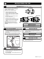
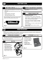
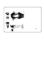
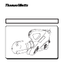
1
2
3
4
4
5
Ni-MH
6
7
27
28
26
25
27
34
18
19
2.0
INSTRUCTIONS FOR USE
2.1
PREPARATION (Refer to Figs. 1, 2 & 3)
BPLT15BSCR
The tool can be easily carried using either the
handle or shoulder strap (19) attached to the
rings (27), see Fig. 1 on page 2.
With the tool at rest, proceed as follows:
• Select the appropriate die set for the
connector. (Ref: Check Thomas & Betts
instruction sheet for the connector and make
sure color code of die matches color code of
connector.)
T&B Series 15600 Dies
• Insert one die into the die adaptor and one
die directly into the head.
DA15-U Adapters
(Optional, see 6.3)
BPLT15BSCR-B
• Insert the conductor in connector.
• Position the connector between the dies and
ensure the correct location of the crimp. (See
connectors instruction sheet for number of
crimps.)
Ensure that the dies are fully secured,
otherwise damage may occur during tool
operation.
Fig. 2
“P” Die
“U” Die
WARNING
When operating the tool, keep hands and other body parts
away from the danger zone.
2.2 DIE ADVANCEMENT (Refer to Fig. 3)
• Press the operating button (26) to activate the
motor-pump and advance the lower die. To halt the
advancement, release the operating button (26) and the
motor will stop.
Make sure the dies are exactly positioned on desired
crimp point, otherwise reopen dies following instructions
as per Step 2.5 and position the connector again.
2.4
HEAD ROTATION
• For ease of operation, the tool head can be rotated
through 180º, allowing the operator to work in the most
comfortable position.
WARNING
Do not attempt to rotate the head when the hydraulic
circuit is pressurized.
26
2.5
25
RELEASE OF DIES
• By pressing the pressure release button (25), the ram
will retract and open the dies.
Fig. 3
2.3
COMPRESSION
• By keeping operating button (26) pressed, the motor
continues to operate: the ram will gradually move forward
until the two dies touch.
• It is recommended to continue pumping until the motor
stops automatically.
TA03982 B Page 3 of 7
3.0
BATTERY USE
The tool is supplied with the batteries completely discharged; before use, fully charge the batteries using the charger supplied.
3.1
BATTERY STATUS (Refer to Fig. 4)
• After releasing the operating button, the residual battery
capacity is automatically displayed for 5 seconds on the
indicator (34). The number of LEDs illuminated indicates the residual
capacity:
8 LEDs illuminated: Fully Charged
4 LEDs illuminated: 50% capacity
1 LED illuminated: Minimum charge
3.2 USING THE BATTERY CHARGER
Carefully follow the instructions in the battery
charger manual.
3.3
USING THE BATTERY
In order to use the batteries correctly,
please follow these rules:
When replacing the battery, press the two points marked
with the word “PUSH” at the same time, remove the flat
battery from its housing and insert the new one.
• Use the battery until the automatic residual energy
display still has 1-2 red LEDs showing: this means the
battery is almost completely discharged and no loss in
the life of the battery has been produced.
• Be particularly careful when charging a new battery
the first 2-3 times in order to maximize the available
energy level.
34
• Allow the battery to cool down to ambient temperature
prior to recharging.
• Rest the battery charger for at least 15 minutes
between charges.
Fig. 4
4.0
MAINTENANCE
The tool is robust, completely sealed, and requires very little daily maintenance. Compliance with the following points,
should help to maintain the optimum performance of the tool:
4.1
THOROUGH CLEANING
Dust, sand and dirt are a danger for any hydraulic device.
Every day, after use, the tool must be wiped with a clean
cloth taking care to remove any residue, especially close
to pivots and moveable parts.
4.2
OIL FILL
Top off the oil, if necessary,
as follows:
- Remove the battery.
- Place the tool in a vertical
position and remove the
filler cap (29) located
inside the battery housing,
taking care not to splash
any oil onto the housing.
- Fill the reservoir to the top.
- Replace the filler cap (29).
Fig. 5
TA03982 B Page 4 of 7
4.3
STORAGE (Refer to Fig 6)
When not in use, the tool
should be stored and
transported in the metal
case, to prevent damage.
This case is suitable for
storing the tool, and its
accessories.
Metal Case: size
22.3x16x5.1 inches,
(566x406x130 mm)
weighs 14.8 lbs. (6,7 kg).
Fig. 6
29
N
P
Q
Q
N-N
P-P
P
N
R
R
Q-Q
R-R
N
N-N
P
N
P
6.3
“U” DIE ADAPTER
DA15-U
Adapter for accepting “U” Dies