1
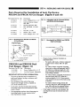
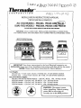
Th
dor
®
CORPORATION
6D 00
INSTALLATION INSTRUCTIONS MANUAL
PROFESSIONAL RANGES
ALL-GAS MODELS - PRG304, PRG36 ANqTPRG48.
DUAL-FUEL MODELS - PRDS304, PRDS36 AND~PRDS48
PLEASE READ ENTIRE INSTRUCTIONS BEFORE PROCEEDING.
IMPORTANT: LOCAL CODES VARY. INSTALLATION, ELECTRICAL CONNECTIONS,
GAS CONNECTIONS. AND GROUNDING MUST COMPLY WITH ALL APPLICABLE CODES.
ill)
—11
IMPORTANT: Save these instructions for the Local Electrical Inspector's use.
INSTALLER: Please leave these Installation Instructions with this unit for the owner.
OWNER: Please retain these instructions for future reference.
Gas Supply:
Natural Gas - 6 inch water column. (14.9mb) min., 8 inch (20mb) nominal
Propane Gas - 11 inch water column. (27.4 mb), 14 inch (37mb) maximum
Electrical Power Supply:
PRG304, PRG36 and PRG48 Models - 120 VAC, 60 Hz.. lPh., 20 Amp circuit.
PRDS304 Model - 120/240 VAC, 50/60 HZ., lPh., 20 Amp circuit.
PRDS36 Models - 120/240 VAC, 50/60 Hz., lPh., 35 Amp circuit.
PRDS48 Models - 120/240 VAC, 50/60 Hz., lPh., 50 Amp circuit.
WARNING: Disconnect power
before installing. Before turning
power ON, be sure that all
controls are in the OFF position.
IMPORTANT INSTALLATION INFORMATION
Model PRDS484GG
INTRODUCTION
(Shown with Low Back Guard Model PRS48LB)
WARNING: Improper
The Thermador Professional*
Ranges are free standing units
installation, adjustment,
alteration, service or main
available in a number of configura
tenance can cause injury or
tions. Model PRG304 is equipped
with four sealed gas surface burn
ers, a large capacity gas oven with
property damage. Refer to
this manual. For assistance
or additional information
gas infra-red broiler and convection
consult a qualified installer,
service agency, manufac
turer (dealer) or the gas
supplier.
\
system. Models PRG364GD.
PRG364GL, and PRG366 feature a
gas cooking surface with four sealed
burners and a griddle, four sealed
/
burners and a grill, or six sealed
— Do not store or use
burners, in addition to a large
capacity gas oven with gas infra-red
gasoline or other
broiler.
Models PRG484GG,
PRG486GD, and PRG486GL feature
flammable vapors and
liquids in the vinicity
of this or any other
appliance.
a gas cooking surface with four
sealed burners, griddle and grill, six
sealed burners and a griddle, or six
sealed.burners and a grill.
WHAT TO DO
IF YOU SMELL GAS
•
•
Do not try to light any
appliance.
Do not touch any
electrical switch; do not
and a small gas oven with broil
capability.
■ Model PRDS304 is equipped with
4
four sealed gas surface burners and
oven with broil capability. Models
Immediately call your
PRDS364GD. PRDS364GL. and
gas supplier from a
1
PRDS366 offer the same cooking
surface configurations but are
neighbor's phone. Fol
low the gas supplier's
i
equipped with a professional size,
instruction.
electric convection, self-cleaning
If you cannot reach your
gas supplier, call the
oven with broil capability. Models
PRDS484GG. PRDS486GD. and
PRDS486GL feature a gas cooking
fire department.
— Installation and service
surface with fo'jr sealed burners,
Model PRDS364GD
griddle and grill, six sealed burners
must be performed by a
and a griddle, or six sealed burners
qualified installer,
(Shown with High Shelf Model PRS36HSI
and a grill. PRDS48 Ranges provide
service agency or the
a large electric oven (toe same as
gas supplier.
>
Model PRG366
(Shown with Island Trim Model PRS36ITI
an electric convection, self-cleaning
building.
•
PRG48
Ranges provide a large gas oven (the
same as used in the PRG36 Ranges)
use any phone in your
•
23
used in the PRDS36 Ranges) and a
'
TA"RT V OF rONTFMT^
small electric oven with a bread
proofing feature and broil capability.
Warning
1-2
Introduction
3
Important Installation Information
3
Step 1: Ventilation Requirements
3
Step 2: Cabinet Preparation
4
Step 3: Unpacking, Moving And Placing The Range
8
Step 4: Install Anti-Tip Device
10
Step 5: Gas Requirements & Hookup
15
Step 6: Electrical Requirements, Connection & Grounding
16
Step 7: Backguard Installation
20
Step 8: Test And Adjustment
21
Installer Checklist
23
52:
V
AVERTISSEMENTS EN FRANCAIS
Thermadar
CORPORATION
For Residential Use Only
®
ALL-GAS MODELS - PRG304 AND PRG36,
DUAL FUEL MODELS PRDS304, PRDS36 AND PRDS48
CET MAN U EL CONTEN IT AVERTISSEMENTS EN FRANCAIS
AVERTISSEMENT: Couper le courant avant d'installer. Avant
de mettre EN MARCHE, soyez certain que tous les controles
sont dans la position ARRETE.
AVERTISSEMENT:
DANGER DE
RENVERSEMENT
DE LA CUISINIERE
^AVERTISSEMENT:
L'lnstallatlon inexacte.
rajustement. la modification, le
service ou l'entretien peut causei
la blessure ou la propriete
endommagee. Serefererace
manuel. Pour l'assistance ou
(1) En branchant l'apparell au
gaz de propane, soyez certain
que le reservoir de gaz du
propane est equipe avec son
regulateur de haute presslon en
addition du regulateur de
celui-ci ou sucum autre
pression fourni avec cet
appareil. La pression de gaz
maximale a cet appareil ne doit
pas exceder une colonne d'eau
de 14.0 pouces du regulateur du
reservoir de gaz du propane.
(2) Cet appareil est dessine
comme un appareil de cuisson.
Base sur les considerations de
securite, ne le jamais utiliser
pour le chauffage ou de falre
appareil.
chauffer une chambre.
rinformation addltionnelle
consulter un installateur
qualifle. une agence de service,
le fabrlcant (le marchand) ou le
fournisseur de gaz.
•
ATTENTION:
Ne pas emmagasuner ou
utiliser de l'essence ou des
autres vapeurs inflammables
et liquides aux endr oits de
CE QUI FAIRE SI VOUS
SBNTEZ LE GAZ.
•
Ne pas essayer d'allumer
aucun appareil.
•
Ne pas toucher aucun
Ne pas installer les
cuisinieres du Modele
PRDS48 tel que la porte du
pas utiliser aucun telephone
four est au ras du devant du
cabinet. Une installation a
dans votre batiment.
ras peut resulter au
interrupteur electrique; ne
•
ATTENTION:
Appeler immediatement votre
four nisseur de gaz du
telephone dun voisin. Suivre
dommage des cabinets par
suite de l'explosition a la
haute chaleur.
l'instruction du four nisseur
de gaz.
•
ATTENTION:
Instructions.
• Si la cuisinifere est tirfee loin
du mur pour le nettcyage,
l'entretien, ou toute autre
raison, assurer que Les
Appareils Anti-Renverses ont
rengages correctement
quand la cuisiniere est
poussfce contre le mur. Dans
revene-ment d'usage
abnormale (tel qu'une
personne qui est debout, est
assise, ou est inclinee sur
une porte ouverte), l'echec
de prendre cette precaution
peut avoir pour le resultat le
renverse-ment de la
cuisiniere. La blessure
elle-meme.
main d'oeuvre adequate
installateur qualife, une
pour eviter le degat et/ ou
la blessure personnelle.
L'appareil est lourd et doit
agence de service ou le
6tre manie in consequence.
doivent etre executes par un
l'appareil n'est pas installe
conformement aux ces
le mouvement de rappareil
contracter votre four nisseur,
• L'installation et le service
ment peut exister si
doivent etre utilises dans
Le materiel adequat et la
incendies.
• Un risque de renverse-
personnelle peut resulter
des liquides chauds
repandus ou de la cuisiniere
Si vous ne pouvez pas
telephoner le service des
• Toutes le cuisinieres
peuvent renverser et la
blessure peut resulter.
Pour empeche le renversement accidentel de la
cuisiniere, l'attacher au
mur, au plancher, ou a
ramoire en installant
L'Appareil Anti-Renvers6
fourni.
fournisseur de gaz.
Page 1
AVERTISSEMENTS EN FRANCAIS
ADVEHnBfflJVIENlY
s
• TOUTESLESCUISINIERES
PEUVENTRENVERSER
• LESBLESSURESAUX
PERSONNES PEUVENT
R&ULTER
• INSTALLER L'APPAREIL
ANTl-RENVERSER EMALLE
AVEC LA CUISINIERE
• VOIR LES INSTRUCTIONS
^INSTALLATION
LES DEGATS DE LA PROTRIETE
• Contacter un installateur ou un entrepreneur du batiment
quallfie pour determiner la methode convenable pour forer
les trous a traverse du materiau du mur du plancher (tel
que ie carreau ceramique, le bols feuillu, et c.)
• Ne pas glisser la culslnlere en traverse d'un plancher qul
n'est pas protege.
• U echec des sulvre oss instructions peut resuter au degats aux
revStements d" mur ou du plancher
AVERTISSEMENT:
ATTENTION:
En branchant l'appareil au gaz de propane
soyez certain que le reservoir de gaz du
propane est £quip£ avec son rggulateur de
haute pression a lui-meme en addition du
regulateur de pression fourni avec l'appare
La pression du gaz fourni avec l'appareil. I
pression du gaz fourni au regulateur de
l'appareil ne doit pas excSder une colonne
d'eau de 14".
>v
<► ATTENTION:
RISQUES D* ELECTROCUTION
Fair preuvre d extreme prudence au cas ou il serait
necessaire de percer le mur ou Ie plancher. Desfils
electriques peuvent etre dlssimules darriere le mur ou sous
le plancher.
Identifier les circuits electriques qul pourraient etre
endommages par 1'instaUatlon du dispositif anti-bascule, et
couper le courant de ces circuits.
L1 echec des suivre ces instructions peut resuter au danger
delectrocution et de blessures.
ATTENTION:
Uapparlel doit etre isole du systeme de tuyauterie de la fourniture de gaz en fermant la soupape a
main d'arret individuel pendant l'essai du systeme de tuyauterie de la fournlture de gaz aux
pressions. d'epreuve egale a ou au moins que 1/2 pslg (3.5 kPa.).
L'appareil et sa soupape d'arrfit Individuel doivent etre deconnectes du systSme de tuyauterie de la
fourniture de gaz pendant l'essai du systeme aux pressions d'epreuve en plus de 1/2 psig (3.5 kPa).
En examlnant la pression de gaz du collecteur, la pression d'entrde au regulateur doit etre au
moins de 6.0"
W.C. pour le gaz naturel ou 11.0" pour le propane.
Ne pas tenter aucun reglage du regulateur de pression.
ATTENTION:
Themador recommande que
les ajustements du bee soient
faits par un technicien
quallfie au temps de
rinstallation. Un soin
extreme doit etre pris quand
les ajustements sont faits
apres l'lnstallation.
Les
ajustements inexacts ou la
manque des ajustements
peut annuler votre garantie.
Page 2
IMPORTANT INSTALLATION INFORMATION
/^IMPORTANT:
ity of this unit, particular attention
should be paid to the hood and duct
work installation to assure it meets
local building codes. To eliminate
risk of burns or fire caused by
reaching over heated surface units,
cabinet storage located above the
surface units should be avoided.
All ranges must be installed with a
backguard. Models PRG304 and
PRDS304 are shipped from the
factory with a standard 9" backguard. For all other models one of
three available backguards must be
ordered separately and installed at
the back of the range. The three
backguard choices include a Low
Back Guard, High Shelf, or Island
Check local building codes for the
proper method of appliance installa
VTrim. See STEPS 2 and 6.
tion. Local codes vary. Installation,
This appliance has been tested in
accordance with ANSI Z21.1 Current
Issue, Standard for Household
Cooking Appliances (USA) and in
must comply with all applicable codes.
In the absence of local codes the
electrical connections and grounding
appliance should be installed in
Domestic Gas Ranges (CANADIAN).
accordance with the National Fuel Gas
Code ANSI Z223.1 Current Issue and
National Electrical Code ANSI/NFPA
It is strongly recommended that this
70-Current Issue. In Canada, installa
accordance with CAN 1.1-M81
tion must be in accordance with the
appliance be installed in conjunction
CAN 1-B 149.1 and .2 - Installation
with a suitable overhead vent hood.
ments.) Due to the high heat capabil-
Codes for Gas Burning Appliances
and/or local codes.
It is strongly recommended that a
hang the range cooking surface by 6"
suitable exhaust hood be installed
on both sides.
(See Step 1 for Ventilation Require
This appliance is equipped with an
intermittent/interrupted ignition
device that cycles the two far left
surface burners on and off when in
the ExtraLow® setting.
<► CAUTION:
(1) When connecting the unit to
propane gas, make certain the
propane gas tank is equipped
with its own high pressure
regulator in addition to the
pressure regulator supplied with
this unit. The maximum gas
pressure to this appliance is not
to exceed 14.0 inches (37mb)
water column from the propane
gas tank regulator.
(2) This unit is designed as a
cooking appliance. Based on
safety considerations never use it
Vjbr warming or heating a room.
STEP1: VENTILATION REQUIREMENTS
above the range. Downdraft ventilation
CAUTION: Ventilation hoods and
blowers are designed for use with
should not be used. The table below
indicates the Thermador hoods, by
single wall ducting. However, some
model number, that are recommended
local building codes or inspectors
for use with the 30", 36". and 48"
may require double wall ducting.
ranges.
Consult local building codes and/or
1. Select Hood and Blower Models:
local agencies, before starting, to
• For wall installations, the hood width
assure that hood and duct installa
tion will meet local requirements.
must, at a minimum, equal the width
of the range cooking surface. Where
space permits, a hood larger in width
• Hood blower speeds should be
variable to reduce noise and loss of
than the cooking surface may be
heated or air conditioned household
desirable for improved ventilation
air when maximum ventilation is not
performance.
required. Normally, the maximum
blower speed is only required when
• For island installations, the hood
RANGE WIDTH
WALL INSTALLATION
HOOD*
30" RANGE
36" RANGE
48" RANGE
Notes
• For best smoke elimination, the
lower edge of the hood should be
installed a minimum of 30" to a
maximum of 36" above the range
cooking surface. (See Fig. 1).
• If the hood contains any combus
tible materials (i.e. a wood covering),
it must be a minimum of 42" above
the cooking surface.
3. Consider Make-Up Air:
• Due to the high volume of ventila
tion air, a source of outside replace
ment air is recommended. This is
particularly important for tightly
sealed and insulated homes.
• A qualified heating and ventilating
contractor should be consulted.
using the grill.
width should, at a minimum, over-
2. Hood Placement:
BLOWER'
PH30HQS
VTR1000Q. VTR1400Q
PHE30.36
orVTNIOOOQ
PH36HQS
VTR1000Q. VTR1400Q
PHE36.42
orVTNIOOOQ
PH48HQS
VTR1000Q. VTR1400Q
PHE48.60
orVTNIOOOQ
ISLAND INSTALLATION
HOOD
BLOWER
PHI48QS
VTR1400Q
PHI48QS
VTR1400Q
PHI60QS
VTR1400Q
' For wall installations where adequate space is available, the installer or user may elect to use a hood that is wider than the range
cooking surface This may be particularly beneficial for those cases, such as a long duct run or heavy usage of the grill, in which
improved capturing of the cooking exhaust is desired
" Thermador offers a choice of remote (VTR1000Q or VTRHOOq) or in-hood (VTN1000Q) blowers for use in wall installations.
Page 3
STEP 2: CABINET PREPARATION
1.
The range is a free standing
4.
unit. If the unit is to be placed
adjacent to cabinets, the
clearances shown in Fig. 1 are
required. The same clearances
apply to island installations,
except for the overhead cabi
nets, which must have a space
5.
6.
wide enough to accept the
flared island hood, as indicated
The PRDS48 Ranges must be
placed with the oven door
projecting out from the cabinet
face. The cabinet face should
line up with the oven front
frame, which is the surface that
the oven door closes against.
(See Fig. 2b and 2c illustrating
side views of 48" ranges.)
3.
required for each type of
head cabinets installed on
either side of the hood is 13".
backguard.
7.
Always keep appliance area
clear and free from combustible
Any openings in the wall behind
the range and in the floor under
the range must be sealed.
materials, gasoline and other
flammable vapors and liquids.
8.
When there is less than a 12"
horizontal clearance between
Do not obstruct the flow of
combustion and ventilation air
to the unit.
combustible material A and the
back edge of the range above
in Fig. 1.
2.
The maximum depth of over
The gas and electrical supply
should be within the zones
shown in Fig. 3a, 3b and 3c.
FIG. 1 Cabinet Clearances
CAUTION:
the cooking surface, a
Thermador Low Back or High
Do not install the iModel
PRDS48 ranges such that the
Shelf backguard must be
installed. (See Fig. 2a). When
oven door is flush with the
clearance to combustible
cabinet face. A flush installa
material A is over 12", a
tion could result in damage to
Thermador Island Trim may be
the cabinets due to exposure
used. (See Fig. 2b). Except in
to high heat.
the case of 30" Ranges,
A
backguards must be ordered
As defined in the "Nationa\ Fue\
separately. Figures 2a. 2b
Gas Code" (ANSI Z223.1. Latest
and 2c indicate the space
Edition).
30" Wide Hood (Model *PH30QS)
48" for Island (Model #PHI48QS)
I For 30' Ranges
36" Wide Hood (Model #PH36QS)
48" for Island (Model #PHI48QS)
j For 36" Rangej
48" Wide Hood (Model 0PH48QS)
60" for Island (Model #PHI60QS)
| For 48' Ranges'
Min. Distance Between Overheaad
-4-»»
alA
Cabinets of Combustible Material
A
30" Range - 30"
36" Range - 36"
48" Range - 48"
30" Min. to 36" Max.
bottom of overhead
18" Min.
Hood to cooking
surface (42" if hood
contains combustible
I
13"M
Cabinet
CAUTION: See
Depth
Range width
30". 36" or 48"
12' Mn to
combus
tible side
wan
combustible
"'
cii .A
materials A)
(bom
Figs. 2a 2b and
2 c 42' Min to
material A.
from cooking
surface
sees!
For Electrical and Gas Supply Zone,
"see Figures 3a, 3b and 3c. Zone size
and position differ according to the
model.
•35-3/8" Min. Range Height with
Leveling Legs fully retracted
•36-3/4" Max. Range Height with
Leveling Legs fully extended
A as defined in the "National Fuel Gas Code" (ANSI Z223.7. Latest
Edition). 'The range height is adjustable. The level of the range top
must be at the same level or above the countertop level.
Page 4
STEP 2: CABINET PREPARATION
FIG. 2a
FIG. 2b
Side View 30" Ranges
- Com
bustible
////
Side View 36" and 48" Ranges
////
////
///S
//// -—Com-
Materials &
28-3/4'
27-5/8"
Optional
High
Shelf
AY Mln. to
Combustibles A
42" Mln. to
Std.
Combustibles A
__
Low Back
Guard
(Provided
with 30" Range)
Clearance
s/ss
ss/s
//
26-3/8'
»►
+— 24-3/8"
*-
16-1/2"—>
A as defined in the 'National Fuel Gas Code*
(ANSI Z223.1. Current issue).
FIG. 2c
Side View 30", 36" and 48" Ranges
CombuHtbte
Materials A
12" Min. to
Combustibles A
CAUTION:
without Backguard
Combustibles A
or with island Trim
Do not install the Model PRDS304 and
Island
Trlrr
PRDS48 ranges such that the front
surface of the oven door is flush with
the cabinet face. A flush installation
could result in damage to the cabinets
due to high heat. The face of the
1-1/2*
cabinet should line up with the oven
front frame. The front frame location
relative to the rear of the range is 24-3/
8" on the PRDS304 and 25" on the
PRDS48, as shown in Figures 2a and
2b.
Clearance
'//// \
777/
////
////
30" Ranges - 26-3/8"
36" & 48" Ranges - 28"
Page 5
STEP 2: CABINET PREPARATION
GAS AND ELECTRIC SUPPLY ZONES:
FIG. 3a
Gas & Electrical Supply Zone for PRG304, PRG36 & PRG48 All-Gas Ranges
5/8" Flex Line to
Typical placement shown.
Other placement of Gas
Appliance
Three-Prong,
with a power supply cord with a three-prong
grounding plug. IT MUST BE PLUGGED
120 VAC
Receptacle
Supply and Electrical
Receptacle within the
Electrical and Gas Supply
The All-Gas Ranges are factory equipped
INTO A MATING, GROUNDING-TYPE. 120
VAC RECEPTACLE THAT IS CON1/2" N P T NECTED TO A CORRECTLY POLARIZED
Gas & Electrical
Supply Zone
Zone is acceptable.
AND GROUNDED 120 VAC CIRCUIT.
(See STEP 6.)
NOTE:
A Manual Gas
The range must beconnected only to the
Shut-Off Valve
(not shown) must
be easily accessible
If the range is to be connected to propane
type of gas for which it is certified.
gas, ensure that the propane gas supply
through an adjacent
tank is equipped with its own high pressure
1 3/4" Maximum
cabinet without moving
regulator in addition to the pressure
Protrusion from Wall
the range.
regulator supplied with the range. (See
for Gas Supply
STEP 5.)
FIG 3b Gas & Electrical Supply Zone for PRDS304 Dual-Fuel Ranges
The Dual-Fuel ranges may be connected
to the power supply with a 3-pole, 3conductor range supply cord kit, a 3-pole,
Appliance
4-conductor range supply cord kit or by
hard-wiring to the power supply. It is the
1/2" N.P.T.
responsibility of the installer to provide the
240 VAC Receptacle
proper wiring components (cord or conduit
(Shown) or Junction
and wires) and complete the electrical
Box
connection as dictated by local codes and
Gas &
ordinances, and/or the National Electric
Electrical
Code. The units must be properly
•^Supply Zone grounded. Refer to Step 6 for details.
Typical placement shown.
5/8" Flex Line to
Other placement of Gas Supply
and Electrical Receptacle
within the Electrical and Gas
Supply Zone is acceptable.
NOTE:
A Manual Gas
Shut-Off Valve
(not shown)
must be easily
The range must be connected only to the
type of gas for which it is certified. If the
accessible
2" Maximum Protru
through an
adjacent cabinet without
sion from Wall for Gas
Supply
moving
4-3/4"
the range.
range is to be connected to propane gas,
ensure that the propane gas supply tank
is equipped with its own high pressure
regulator in addition to the pressure
regulator supplied with the range. (See
STEP 5.)
FIG. 3c Gas & Electrical Supply Zone for PRDS36 and PRDS 48 Dual-Fuel Ranges
The Dual-Fuel ranges may be connected
Typical placement shown.
Other placement of Gas Supply
and Electrical Receptacle
5/8" Flex Line to
Appliance
within the Electrical and Gas
Supply Zone is acceptable.
240 VAC Receptacle
(Shown) or Junction
NOTE:
Box
A Manual Gas
Shut-Off Valve
(not shown)
must be easily
accessible
through an
adjacent cabinet without
moving
the range.
PRDS36
7"
PRDS48
12"
Supply Zone
and wires) and complete the electrical
connection as dictated by local codes and
ordinances, and/or the National Electric
Code. The units must be properly
grounded. Refer to Step 6 for details.
The range must be connected only to the
type of gas for which it is certified. If the
2" Maximum
Protrusion from Wall
for Gas Supply
range is to be connected to propane gas,
ensure that the propane gas supply tank is
equipped with its own high pressure
regulator in addition to the pressure regulator
supplied with the range. (See STEP 5.)
B
Model
Electrical
to the power supply with a 3-pole, 3conductor range supply cord kit, a 3-pole.
4-conductor range supply cord kit or by
hard-wiring to the power supply. It is the
responsibility of the installer to provide the
proper wiring components (cord or conduit
16"
Page 6
STEP 2: CABINET PREPARATION I
ELECTRICAL SUPPLY, DUAL FUEL RANGES
Installation of Dual Fuel ranges
This is especially critical if the
must be planned so that the
junction box in the wall will be
rough-in of the junction box for
directly behind the junction box
on the unit when the unit is
the receptacle or conduit connec
tion will allow maximum clear
ance to the rear of the unit.
installed. Refer to Figures 16
and 16a for location of junction
box on unit. Orient the recep
tacle or conduit connector to
When the power supply cord (not
supplied) or conduit is connected
to the mating receptacle or
junction box cover, the combined
plug/receptacle or junction box
cover/conduit connector should
protrude no more than 2-1/4
minimize binding when the unit
is connected to the receptacle or
junction box and slid back in
position.
inches from the rear wall. See
Figure 3d.
FIG. 3d
Wall Connection
2-1/4" Max
n
2-1/4" Max. When
Plugged in
Junction Box & Conduit
Power Cord & Receptacle
Page 7
STEP 3: UNPACKING, MOVING AND PLACING THE RANGE
<►
CAUTION:
Proper equipment and
adequate manpower must
be used in moving the range
Chart A
30" Range
36" Range
48" Range
Shipping Weight
335 lbs.
444 lbs.
584 lbs.
Weight without
285 lbs.
390 lbs.
524 lbs.
215 lbs.
295 lbs.
395 lbs.
to avoid damage to the unit
packing materials
or the floor. The unit is
heavy and rests on adjust
able steel legs.
After removing door(s),
burner caps, front kick
• The range has an approximate
30" Range
Chart B
shipping weight as shown in
Chart A. It is recommended that
the door(s), grates, burner caps,
front kick panel and oven racks be
removed to facilitate handling.
This will reduce the weight as
shown in Chart A and allow the
J
V panel and oven racks
Doorway Width Required 28-7/8"
36" Range
48" Range
30-7/8"
30-7/8"
29-1/2"
29-1/2"
(Unit Assembled)
Doorway Width Required 27-3/4"
.
(Oven Door(s) Removed)
range to pass through 30" door
ways. See Chart B and Fig. 2a and
2b. Do not remove the grill or
griddle assemblies.
FIG. 4 All Ranges - Removal of
Kick Panel and Two Front
Shipping Bolts
FIG. 5 All-Gas and Dual Fuel
Ranges -Removal of Two Rear
Shipping Bolts
• Remove the outer carton and
packing material from the ship
ping base. Remove the front kick
panel (see Fig. 4) by removing two
(2) screws at the top and pulling
forward. The dual fuel ranges are
held to the skid by four (4) bolts,
the front two (2) are behind the
kick panel (see Fig. 4) and the
rear two (2) are located on the
bottom flange of the range back
Kick
(see Fig. 5). All-gas ranges are
Panel
held in place by 4 bolts, two (2)
as shown in Fig. 4 and two (2) at
FIG. 6
the rear as shown in Fig. 5. After
All Ranges Door Removal
removing the bolts the range
must be lifted and removed from
Hinge Latch
the skid.
• To remove the door, open the
door to the fully open position.
Close the hinge latches (See Fig.
6) by rotating towards the door
top. The door can then be re
moved by gently lifting and
pulling the door, with the hinges
Hinge Clip In
Locked Position
up and out of the frame. Do not
lift the range by the door
handle(s).
Page 8
Lower Clip After
Replacing Door
STEP 3: UNPACKING, MOVING AND PLACING THE RANGE
Due to the weight, a dolly with soft
wheels should be used to move this
unit. The weight must be supported
uniformly across the bottom (See
Dolly Positioning
Range
Must be
Fig. 7).
Uniformly
Supported
by Braces
Provided
on Bottom
yof Range
After transporting the professional
range by dolly close to its final
location, the range can be tipped
back and supported on the rear
legs while the dolly is carefully
removed. THE FLOOR UNDER
THE LEGS SHOULD BE PRO
TECTED (WOOD STRIPS, CAR
PET, PANELING, ETC.) BEFORE
PUSHING THE UNIT INTO POSI
TION. The anti-tip device (30" and
36" ranges) must be installed (STEP
4). gas and electric connections
should be made (STEPS 5 and 6).
and the backguard installed (STEP
7) before the range is placed in its
final position.
For proper performance the profes
sional range must be level. The
range is leveled by adjusting the
legs with a wrench. Replace the
kick panel and oven doors by
reversing the procedure described
above. It is important that the
two (2) screws retaining the kick
panel are secure to prevent
accidental access to live electri
Griddle Level Adjustments
The griddle should be level or tilted slightly forward
and should not rock. Screws are installed in the back
ledge to eliminate rocking and to adjust the level of
the griddle. To access these screws (A) (see Fig. 8),
carefully remove the black aluminum trim strips
running front to back alongside the griddle, then lift
the back of the griddle.
cal components and wires.
FIG. 8 Griddle Leveling Screws
griddle
leveling screw
Page 9
■ STEP 4: INSTALLING ANTI-TIP DEVICE
For all 30" and 36" ranges, an anti-tip device must be installed
as per these instructions.
WARNING
RANGE TIPPING HAZARD
•
ALL RANGES CAN TIP
All ranges can tip and injury could
result. To prevent accidental tipping of
the range, attach it to the wall, floor or
INJURY TO PERSONS
COULD RESULT
cabinet by installing the Anti-Tip Device
INSTALL ANTI-TIP
supplied.
•
A risk of tip-over may exist if the appli
ance is not installed in accordance with
these instructions.
•
If the range is pulled away from the wall
DEVICES PACKED
WITH RANGE
SEE INSTRALLATION
INSTRUCTIONS
for cleaning, service, or any other rea
son, ensure that the Anti-Tip Device is
properly reengaged when the range is
pushed back against the wall. In the
event of abnormal usage (such as a
person standing, sitting, or leaning on an
open door), failure to take this precau
tion could result in tipping of the range.
Personal injury might result from spilled
hot liquids or from the range itself.
CAUTION
PROPERTY DAMAGE
Contact a qualified installer or contrac
tor to determine the proper method for
•
WARNING
drilling holes through the wall or floor
ELECTRICAL SHOCK HAZARD
etc.)
Use extreme caution when drilling holes
Do not slide the range across an unpro
into the wall or floor. There may be
tected floor.
concealed electrical wires located behind
Failure to follow these instructions may
material (such as ceramic tile, hardwood,
the wall or under the floor.
•
result damage to wall or floor coverings.
Identify the electrical circuits that could
be effected by the installation of the
Anti-Tip Device, then turn off power to
these circuits.
•
Failure to follow these instructions may
result in electrical shock or other per
sonal injury.
Tools Needed for Installation of Anti-Tip Device:
- Screwdriver, Phillips
- Hammer
- Drill, electric or hand
- Pencil or other marker
- Measuring tape or ruler
- Wrench, 7/16" (PRG Ranges only)
- 1/8" drill bit (wood or metal wall or floor)
- Wrench adjustable (PRG Ranges only)
- 3/16" carbide-tipped masonry drill bit (concrete or concrete block wall or floor)
- 3/16" anchors, drywall or concrete, 2 each (not required if mounting bracket is being attached to solid
wood or metal)
Page 10
STEP 4: INSTALLING ANTI-TIP DEVICE
Parts Required for Installation of Anti- Tip Device:
PRG304 and PRG36 All Gas Ranges (Figures 9 and 10)
Thermador Part No.
Qty
Description
15-10-916
4
Screw. Phillips,#10 x 1-1/2'
15-10-771
1
Anti-Tip Channel, Adjust
FIG. 10
Adjustable Anti-Tip Channel PRG304
and PRG36 All-Gas Ranges
able. PRG
15-10-772
1
Mounting Bracket. PRG
15-10-909
1
Bolt. Hex Head. l/4"-20x
■5-1/2"
15-10-910
1
Nut. Hex. 1/4-20
15-10-911
2
Washer. Flat. 1/4-20
15-10-948
2
Screw, Phillips. #10 x 1/2"
FIG. 9
This Hole
This Hole
For Flush
1/2"
For Flush
Mount of
PRG36
Mount of
PRG 304
1-17/32"
1-9/32"
Mounting Kit for PRG304 and PRG36
FIG. 11
All-Gas Ranges
Mounting Kit for PRDS304 and PRDS36
Dual Fuel Ranges
Mounting Bracket
15-10-772(1 Each)
15-10-909(1 Each)
15-10-770(1 Each)
15-10-916 (4 Each)
15-10-916 (4 Each)
15-10-771 (1 Each)
15-10-911 (2 Each)
Prepare holes at fastener locations as
identified below:
15-10-910(1 Each)
15-10-948 (2 Each)
For walls, wall studs, or floors composed
of solid wood or metal, drill 1/8" pilot
PRDS304 and PRDS36 Dual
holes.
Fuel Ranges (Figure 11)
Thermador Part No.
15-10-916
15-10-770
For walls or floors composed of drywall,
sheet-rock or other soft materials, drill 3/
Qty
Description
4
Screw. Phillips,#10x 1-1/2"
16" holes to a minimum depth of 1-3/4",
Anti-Tip Channel, Adjustable,
then tap plastic anchors into each of the
1
IMPORTANT INSTALLATION INFORMATION:
•
thickness of 3/4".
The thickness of the wall or floor may
a hammer.
The anti-tip bracket may be attached to a
solid wood cabinet having a minimum wall
•
•
require use of longer screws, available at
For walls or floors having ceramic tile
your local hardware store.
covering, drill 3/16" holes through the tile
only, then drill into the material behind
In all cases, at least two (2) of the bracket
the tile as indicated immediately above.
mounting screws must be fastened to solid
If the range is moved to a new location, the
Anti-Tip Device must be removed and rein
wood or metal.
•
holes using a hammer.
For walls or floors composed of concrete or
concrete block, drill 3/16" holes to a
minimum depth of 1-3/4", then tap con
crete anchors into each of the holes using
Use appropriate anchors when fastening the
stalled.
mounting bracket to any material other
than hardwood or metal.
Page 11
STEP 4: INSTALLING ANTI-TIP DEVICE
PRG304 AND PRG36 All-Gas Ranges (Figures 9, 10, 12a 12b and 13)
STEP A:
Determine the best location for the
PRG Mounting Bracket. The bracket may be
mounted to the wall or floor behind the
range, offset from either the left or right side
wall by 2-3/4" for model PRG304 or
FIG. 12a
PRG36 Wall Mount (0" Clearance)
PLAN VIEW
4-5/8" for Model PRG36.
Locate the bracket on the side of the
range that will not interfere with the
gas supply line, electrical wiring,
conduit or any other item.
Select either the rear wall or the floor
T
for mounting the bracket, based
upon which will provide the greatest
holding strength.
May Bo Used On Enhef Le't
o> Right Side (Right Sno.vn)
STEP B:
Set the bracket on the floor and turn it
SIDE VIEW
until it is oriented properly. The bracket should
be standing up on end. The set of mounting
flanges having one (1) hole per side should be
resting on the floor, and the other set of
mounting flanges having two (2) holes per side
should be positioned vertically facing the rear.
STEP C:
Slide the bracket left or right to the
correct position for the model that you are
installing. The distance from the side wall to the
center line of the closest mounting hole is 2-3/4"
for model PRG304 or 4-5/8" for Model PRG36.
FIG. 12b
PRG Wall Mount (Max 2" Clearance)
PLAN VIEW
STEP D: If you plan to mount the bracket to the
rear wall, slide the bracket back until it is
positioned against the rear wall. If you plan to
mount the bracket to the floor, position the
bracket such that the center line of the mount
ing holes in the horizontal bracket flanges are
7/16" in front of the rear edge of the range
side panel when the range is in its final in
stalled position.
May Be Used O^ Ennor left
STEP F:
I ^a^'
or RiQhi Side (Rici'i: Shown!""""' .. "
STEP E: With the bracket properly positioned,
use the bracket as a template and mark the
location of the selected mounting holes in
either the rear wall 1 (4 holes) or the floor (2
holes) with a pencil.
Drill holes at the marked locations.
STEP G: Using the screws provided, securely
fasten the bracket to the rear wall (4 screws) or
floor (2 screws).
Page 12
STEP 4: INSTALLING ANTI-TIP DEVICE
STEP H:
Using the l/4"-20 x 1/2" Hex Head
Bolt, Hex Nut and two (2) Flat Washers,
FIG. 13 PRG36 Floor Mount
securely attach the Adjustable Anti-Tip
PLAN VIEW
Channel to the existing hole in the flange
located at the bottom rear of the range.
(There are two (2) holes in the range flange,
Anti-Tip Channel
so be certain to select the hole that is on the
same side as the mounting bracket.) The
O O O O'
flat face of the channel should be flush
*— Mounting Bracket
against the underside of the range flange.
From the bottom of the channel, screw the
two (2) #10 x 1/2" Phillips Screws up
through the first pair of holes extending
beyond the rear edge of the range flange.
These screws will prevent rotation of the
channel. Note: A number of mounting
holes are provided in the Adjustable
Anti-Tip Channel. Be certain to use the
hole that enables the channel to engage
the mounting bracket when the range is
in its final installed position. For
ranges that are to be installed flush
against a rear wall, use the first hole in
the Adjustable Anti-Tip Channel, such
that the short portion of the channel
extends out from the bottom of the range
flange and the long portion is hidden
beneath the range.
"T
PRG304: 2-3/4"
PRG36: 4-5/8"
±
May Be Used On Either Left
or Right Side (Right Shown)
SIDE VIEW
-Anti-Tip Channel
Leveling Leg -
- Mounting Bracket
AND THE ADJUSTABLE MOUNTING CHAN
Refer to Figure 10.
NEL MUST BE ATTACHED TO THE APPRO
PRIATE MOUNTING HOLE.
STEP I:
REMOVE ANY
LOOSE ITEMS SUCH AS GRATES AND
Carefully slide the range into position.
FOR THE ANTI-TIP CHANNEL TO ENGAGE
BURNER CAPS FROM THE TOP OF THE
THE MOUNTING BRACKET, THE REAR
RANGE, THEN CAREFULLY TILT THE
EDGE OF THE RANGE SIDE PANEL MUST
RANGE FORWARD TO ENSURE THAT THE
BE WITHIN 2" OF THE VERTICAL MOUNT
ANTI-TIP DEVICE ENGAGES TO PREVENT
ING FLANGE OF THE ANTI-TIP BRACKET,
TIPPING.
PRDS304 AND PRDS36 Dual-Fuel Ranges (Figures 11, 14 and 15)
STEP A:
Determine the best location for Anti-
For Model PRDS304, the dimensions
shown are from the left side wall only.
Tip Channel Mounting Bracket. The bracket
may be mounted to the wall or floor behind
For Model PRDS36, the dimensions
shown are from either the left or right
side wall. Locate the bracket on the
side of the range that will not interfere
the range, offset from side wall as indicated
in the chart below and in Figures 14 and 15:
Model No.
"A", Min.
"B", Max.
PRDS304
5-1/2"
16-1/2"
PRDS36
6-1/2"
13-1/2"
with the gas supply line, electrical
wiring, conduit or any other item.
Select either the rear wall or the
floor for mounting the bracket,
based upon which will provide the
greatest holding strength.
Page 13
STEP 4: INSTALLING ANTI-TIP DEVICE
STEP B: Set the bracket on the floor and turn
it until it is oriented properly. The long
channel should be on the top with the free
end facing towards you, one set of mounting
FIG. 14 PRDS Wall Mount
flanges should be resting horizontally on
PLAN VIEW
the floor, and the other set of mounting
flanges should be positioned vertically
facing the rear.
STEP C:
Slide the bracket to the desired
position. Note that the minimum (dim. "A")
and maximum (dim. nB") spacing from the
side wall to the center line of the closest
bracket mounting hole is as shown in the
chart above and in Figures 14 and 15.
STEP D:
SIDE VIEW
If you plan to mount the bracket to
the rear wall, slide the bracket back until it
is positioned against the rear wall. If you
plan to mount the bracket to the floor,
position the bracket such that the center
line of the mounting holes in the horizontal
bracket flanges are 7/16" in front of the
rear edge of the range side panel when the
range is in its final installed position.
STEP E:
With the bracket properly posi
FIG.15 PRDS Floor Mount
tioned, use the bracket as a template and
mark the location of the selected four (4)
mounting holes.
STEP F:
PLAN VIEW
Drill four (4) holes at the marked
locations.
STEP G:
Using the four (4) screws provided,
securely fasten the bracket.
STEP H:
Carefully slide the range into
position.
FOR THE ANTI-TIP DEVICE
TO ENGAGE THE RANGE, THE REAR
Sr-o-.vn [(Oil
EDGE OF THE RANGE SIDE PANEL
le't S cle Wan
MUST BE WITHIN 2" OF THE VERTI
CAL MOUNTING FLANGE OF THE ANTITIP BRACKET, REMOVE ANY LOOSE
ITEMS SUCH AS GRATES AND BURNER
CAPS FROM THE TOP OF THE RANGE,
THEN CAREFULLY TILT THE RANGE
FORWARD TO ENSURE THAT THE
ANTI-TIP DEVICE ENGAGES TO PRE
VENT TIPPING.
Page 14
SIDE VIEW
STEP 5: GAS REQUIREMENTS AND HOOKUP
Verify the type of gas being used at the installation site.
As shipped from the factory, all units are configured for
use on natural gas. For use with propane gas, the unit
must be converted. Field conversion for use with
propane must only be done by qualified service person
nel. Contact the dealer where the unit was purchased
or Thermador (800/735-4328). The field conversion kit
for all Professional Series ranges is Thermador Model
STARLPKIT.
• A manual gas shut-off valve must be installed
external to the appliance, in an accessible location
from the front, for the purpose of shutting off the gas
supply. The supply line must not interfere with the
back of the unit. Make sure the gas supply is turned
off at the manual shut-off valve before connecting the
appliance.
For installation of the appliance at high altitude, please
consult your local gas company for their recommenda
tion of the correct orifice sizes and any other necessary
adjustments that will provide proper gas combustion at
specified altitudes.
<►
HOOK UP
• The range is supplied with its own pressure regulator
that has been permanently mounted within the range
body.
• Use 5/8" flex line to connect between the gas supply
CAUTION:
When connecting unit to propane gas, make
certain the propane gas tank is equipped with
its own high pressure regulator in addition to
the pressure regulator supplied with the
appliance. The pressure of the gas supplied to
the appliance regulator must not exceed 14"
(37mb) water column.
and the appliance manifold pipe, which exits the
upper left rear of the appliance. The appliance
manifold pipe connection is 1/2" NPT. (See Fig. 3a,
3b, or 3c.) Use caution to avoid crimping the 5/8" flex
line when making bends.
• The gas supply connections should be made by a
competent technician and in accordance with local
codes or ordinances. In the absence of a local code,
the installation must conform to the National Fuel
Gas Code ANSI Z223.1. Current Issue.
Natural Gas Requirements:
Inlet Connection:
1/2" N.P.T. (Minimum 5/8"
dia. flex line.)
Supply Pressure: 6" to 14" water column. (14.9
to 37 mb)
Manifold Pressure: 5" water column (12.5 mb)
• Always use pipe dope or Teflon® tape on the pipe
threads, and be careful not to apply excessive pres
sure when tightening the fittings.
• Turn on gas and check supply line connections for
leaks using a soap solution. Do not use a flame of
any sort to check for leaks.
Propane Gas Requirements:
Inlet Connection:
1/2" N.P.T. (Minimum 5/8"
dia. flex line.)
Supply Pressure:
11" to 14" water column.
(27.4 mb to 37 mb)
Manifold Pressure:
<►
10" water column (24.9 mb)
CAUTION:
"The appliance must be isolated from the gas supply piping system by closing its individual manual shutoff valve during any pressure testing of the gas supply piping system at test pressures equal to or less
than 1/2 psig (3.5kPa.)."
"The appliance and its individual shut off valve must be disconnected from the gas supply piping system
during any pressure testing of the system at test pressures in excess of 1/2 psig (3.5kPa.)."
When checking the manifold gas pressure, the inlet pressure to the regulator should be at least
6.0" (14.9 mb) W.C. for natural gas or 11.0" (27.4 mb) for propane.
Do not attempt any adjustment of the pressure regulator.
Page 15
STEP 6: ELECTRICAL REQUIREMENTS, CONNECTION & GROUNDING
Prior to servicing appliance, always
disconnect appliance electrical
supply cord, if so equipped, from
wall receptacle. If appliance is hard
wired to power supply, disconnect
Dual Fuel range models
PRDS304. PRDS36 and
proper circuit breaker or
disconnecting the proper fuse.
PRDS48 can be cord-con
nected or hard-wired to the
power supply, as described on
Gas range models PRG304,
PRG36 and PRG48 must be
Page 17.
plugged into a 3-prong
power to unit by turning off the
grounding type receptacle.
Chart C: ELECTRICAL SUPPLY CIRCUIT REQUIREMENTS
MODEL NUMBER
VOLTAGE
CIRCUIT RATING
FREQUENCY
PHASE'
PRG304. PRG36
120 VAC
15 Amps
50/60 Hz.
Single
PRDS3O4
120/240 VAC
20 Amps
50/60 Hz.
Single
PRDS36
120/240 VAC
35 Amps
50/60 Hz.
Single
PRDS48
120/240 VAC
50 Amps
50/60 Hz.
Single
and PRG48
V
For the PRG All-Gas Ranges,
improper polarization of the
For the PRDS Dual-Fuel
Ranges, a neutral supply wire
absence of local codes and
ordinances, the power supply
120 VAC electrical supply
circuit will cause malfunction
must be provided from the
power source (breaker/fuse
dance with the National
(such as continuous sparking of
the burner igniters), may
damage this appliance, and
could create a condition of
shock hazard at the igniter of
panel) because critical range
Electric Code.
components, including the
surface burner spark
reignition module, require
120 VAC to operate safely and
Observe all governing codes
and ordinances when ground
ing. In the absence of these
each burner. If the circuit is not
properly. An improper
correctly polarized, it is the
responsibility and obligation of
the installer or user to have the
existing receptacle changed to
a properly polarized receptacle
in accordance with all appli
cable local codes and ordi
nances by a qualified electri
cian. In the absence of local
codes and ordinances, the
receptacle replacement shall be
in accordance with the National
120/240 VAC power supply
will cause malfunction,
damage this appliance, and
possibly create a condition of
Electric Code.
connection shall be in accor
codes or ordinances observe
National Electrical Code ANSI/
NFPA No. 70 Current Issue.
See pages 17 and 18 for
grounding method.
shock hazard. If the correct
Electrical wiring diagrams and
power supply circuit is not
schematics have been placed in
provided, it is the responsibil
ity and obligation of the
installer or user to have proper
the toe kick area of the range
for access by a qualified service
power supply connected. This
technician.
must be accomplished in
accordance with all applicable
local codes and ordinances by
a qualified electrician. In the
The PRDS Dual Fuel Ranges
may be connected to a 120/
208 VAC power supply.
Chart D: POWER SUPPLY WIRE - RATING AND SIZE REQUIREMENTS
MODEL
NUMBER
VOLTAGE
RATING. MIN.
RATING
CONDUCTOR SIZE . AWG
GROUND
L1.L2
NEUT
TEMPERATURE
PRDS304
300 VAC
105°C
10
12
10
PRDS36
300 VAC
105°C
10
12
10
PRDS48
300 VAC
105°C
8
10
8
Page 16
STEP 6: ELECTRICAL REQUIREMENTS, CONNECTION & GROUNDING
Dual Fuel models PRDS304, PRDS36 and PRDS48 must be connected to the power supply utilizing one of the
following methods. For all methods of connection, the length of the cord or conduit/wiring must allow the unit to
be slid completely out of the cabinet without having to unplug or disconnect the unit from the power supply.
Recommended minimum free length of cord or conduit is four feet. Electrical installations and grounding must
be in accordance with all local codes and ordinances, and/or the National Electric Code, as applicable.
• 3-CONDUCTOR CORD- Where
local codes and ordinances
permit grounding through
neutral, unit may be connected
to the power supply with a 3-
pole, 3-conductor cord kit rated
125/250 volts, 50 amperes, and
marked for use with ranges. The
cord kit must be attached to the
range junction box with a strain
relief which will fit a 1 -3/8"
diameter hole. If not already
equipped, the cord must have
#10 closed-loop lugs attached to
the free ends of the individual
conductors, preferably soldered
in place.
Locate the junction box on the
rear of the unit and remove
cover.
Refer to Fig. 16 for
PRDS304 range and Fig. 16a for
PRDS36 and PRDS48 ranges.
Remove the knock out ring in
the junction box to provide a 1 3/8" diameter hole. Install the
ends of the individual conduc
tors, preferably soldered in place.
Locate the junction box on the
rear of the unit and remove
cover. Refer to Fig. 16 for
PRDS304 range and Fig. 16a for
PRDS36 and PRDS48 ranges.
Remove the knock out ring in the
junction box to provide a 1 -3/8"
diameter hole. Remove the
ground strap retaining screw and
bend the ground strap up. Refer
to Fig. 18. Install the cord to the
junction box, and make the
connections to the terminal block
provided. Secure the ground
lead from the cord to the junc
tion box with the screw previ
ously used to secure the ground
strap. Refer to Fig. 18a. The
cord kit must be plugged into a
mating NEMA 10-50R receptacle
provided in the gas and electrical
supply zone, as shown in Figures
conductors. The ends of the
wiring must have #10 closed-
loop lugs attached, preferably
soldered in place. Make the
connections to the terminal
block provided. Secure the
ground lead to the junction box
with the screw previously used
to secure the ground strap.
Refer to Fig. 18a. The frSe end
of the conduit must be con
nected to a junction box pro
vided in the gas and electrical
supply zone, as shown in
Figures 3b and 3c on Page 6.
FIG. 16 Location of Junction Box
on PRDS304 Range
3b, and 3c on Page 6.
cord to the junction box, and
make the connections to the
PERMANENT CONNECTION
terminal block provided. Refer
(HARD WIRING)- Units may be
hard wired to the power supply.
to Figures 17 and 17a. The cord
kit must be plugged into a
The installer must provide
mating NEMA 10-50R receptacle
approved flexible aluminum
Width
conduit, 3/4" trade size, maxi
of J-Box
provided in the gas and electrical
supply zone, as shown in
Figures 3b. and 3c on Page 6.
• 4-CONDUCTOR CORD- Where
local codes and ordinances DO
NOT PERMIT GROUNDING
THROUGH NEUTRAL unit must
be connected to the power
supply with a 3-pole, 4-conduc
tor cord kit rated 125/250 volts,
50 amperes, and marked for use
with ranges. The cord kit must
mum 6 feet long. Locate the
junction box on the rear of the
unit and remove cover. Refer to
Hole for
Connection of
Cord 67 Conduit
FIG. 16a Location of Junction Box
on PRDS36, 48.
Fig. 16 for P*RDS304 range and
Fig. 16a for PRDS36 and
PRDS48 ranges. Remove the
ground strap retaining screw and
bend the ground strap up. Refer
to Fig. 18. The conduit must be
installed to the junction box
Hole for Con
nection of Coed
or Conduit
using an approved conduit
connector.
be attached to the range junc
tion box with a strain relief
which will fit a 1-3/8" diameter
hole. If not already equipped,
the cord must have #10 closed-
loop lugs attached to the free
Wiring for the unit is to be
brought into the junction box
through the conduit. Refer to
Chart D on Page 16 for rating of
wiring and sizing of individual
Page 17
6*WidthofJ-Box
MODEL
DIM "A"
PRDS36
13-1/4"
PRDS48
19"
STEP 6: ELECTRICAL REQUIREMENTS, CONNECTION & GROUNDING
A 3 or 4 conductor supply may be connected to
the terminal block. A 4 conductor supply shall
be used only when the range is installed in a
mobile home or where local codes do not
permit grounding through the neutral.
FIG.17
Conductor Securement
Upper Nut
^-Cupped Washer
*"- Supply Wire
lat Washer
3 WIRE LEAD CONNECTION
1.
Remove upper nuts only from the terminal
block studs. Do not remove nuts which
secure range internal wiring leads.
2.
Secure the neutral, grounded wire of the
supply circuit, to the center stud of the
terminal block with nut. (See Fig. 17a).
3.
FIG. 17a
3 Wire Connection
Secure the LI (black) and L2 (red) power leads
to the outside terminal block studs (brass
colored) with nuts.
4.
Tighten nuts securely.
4 WIRE CONNECTION
1.
L2Red
Neutral White
Remove upper nuts only from the terminal
block studs. Do not remove lower nuts
which secure range internal wiring
leads.
FIG. 18 Ground Strap
2.
Remove ground strap screw and bend the
strap up as shown in Fig. 18)
3.
Secure the neutral wire to the center stud of
the terminal block with nut. Tape neutral
wire and connector, as shown in Fig. 18a to
insure strap does not contact a grounded
surface.
4.
Secure the LI (black) and L2 (red) power
leads to the outside terminal studs (brass
Bend Ground Strap Up
colored) with nuts.
5.
Secure the bare copper ground lead to the
range chassis using the ground screw previ
FIG. 18a
Secure Neutral Wire
ously used for the ground strap.
6.
Tighten all connections securely.
L1 Black
Ground Wire
Page 18
STEP 6: ELECTRICAL REQUIREMENTS, CONNECTION & GROUNDING
Recommended Grounding Method - All-Gas
Models PRG304, PRG36 and PRG48
The 30," 36" and 48" all-gas ranges are factory equipped with a power
supply cord with a three-prong grounding plug (with polarized parallel
blades). IT MUST BE PLUGGED INTO A MATING GROUNDING TYPE
RECEPTACLE THAT IS CONNECTED TO A CORRECTLY POLARIZED 120
VOLT CIRCUIT. (See Fig. 19). Improper grounding will cause malfunc
tion (such as continuous sparking of the burner igniters), may
damage this appliance, and could create a condition of shock
hazard at the igniter of each burner. If the circuit does not have a
grounding type receptacle, it is the responsibility and obligation of the
installer or user to have the existing receptacle changed to a properly
grounded receptacle in accordance with all applicable local codes and
ordinances by a qualified electrician. In the absence of local codes and
ordinances, the receptacle replacement shall be in accordance with the
National Electric Code. THE THIRD GROUND PRONG SHOULD NOT,
UNDER ANY CIRCUMSTANCES, BE CUT OR REMOVED.
Alternate Grounding Method - All-Gas
Models PRG304, PRG36 and PRG48
FIG. 19 Recommended
Grounding Method Models PRG304, PRS36
and PRG48
THREE-PRONG
RECEPTACLE
THREE-PRONG
PLUG
FIG. 20 Alternate
Grounding Method Models PRG304, PRG36
and PRSG48
If installing a properly grounded wall receptacle is impossible at the time of
installation, consult your local electrical inspector for permission to
connect a temporary adapter (with polarized blades) which could be
plugged into your present 2-wire receptacle.
(See Fig. 20). This method is not recommended.
If this is done, you must attach the lug and/or the green adapter wire to
the receptacle cover plate screw. Ground from it to a grounded metal cold
water pipe. (See Fig. 21).
DO NOT GROUND TO A GAS SUPPLY PIPE.
Grounding Method - Dual-Fuel
Models PRDS304, PRDS36 and PRDS48
FIG. 21 Grounding Method Models PRDS304,
All ranges must be properly grounded. See the grounding instructions for
your installation case, as follows. Refer also to the instructions and
PROS36 and PRDS48
Figures on Pages 17 and 18.
CASE 1: Electrical Connection and Grounding with a 3 Conductor Power
Supply (To be used when local codes permit grounding through
the neutral.) Secure the neutral, grounded wire of the supply
circuit to the neutral terminal of the NEMA 10-50R receptacle.
Connect the L! (black) and the L2 (red) hot heads to the other
terminals on the NEMA 10-50R receptacle. A separate ground
wire is not required. Ensure that the house supply wires and all
electrical connections meet the requirements of all applicable
codes.
Page 19
METER
CLAMP
METAL WATER PIPE
STEP 6: ELECTRICAL REQUIREMENTS, CONNECTIONS & GROUNDING
CASE 2: Electrical Connections and Grounding
- with a 4-Conductor Power Supply (to be
used only when local codes do not permit
grounding through the neutral). Secure the
neutral (white) wire of the supply circuit to the
neutral terminal of the NEMA 14-50R recep
tacle. Connect the LI (black) and the L2 (red)
hot leads to the other terminals on the NEMA
and connected to the box. per the
instructions.
Ensure that the house supply wires and
all electrical connections meet require
ments of all applicable codes.
DO NOT GROUND TO A GAS SUPPLY PIPE.
14-50R receptacle. Connect a separate
ground (green) wire to the grounding terminal
of the NEMA 14-50R receptacle.
Improper grounding will cause malfunction (such
as continuous sparking of the burner igniters),
may damage this appliance, and could create a
If range is hard-wired to power supply, follow
condition of shock hazard at the igniter of each
burner. It is the responsibility and obligation of
the instructions for permanent connection on
pages 17 and 18. The ground wire must be
the installer or user to ensure that the appliance
is properly grounded.
brought out to the junction box on the range
STEP 7: BACKGUARD INSTALLATION
The backguard must be attached
before sliding the range into the
final installed position. A Low Back
or High Shelf backguard must be
installed when there is less than a
12" clearance between combustibles
and the back of the range above
the cooking surface. (See Fig. 2a
FIG. 22
and 2b).
Front of Unit
An Island Trim is available for
covering the backguard mounting
flanges for island installations,
where there is a minimum of 12" of
horizontal clearance between
combustibles and the back of the
range. (See Fig. 2c).
The backguard is inserted, as
shown in Fig. 22, into the guide
channels on the back of the range.
Secure the backguard with the (4)
sheet metal screws provided.
For installation of backguards
on all models, refer to the following
instructions on Page 21.
Chart D: BACKGUARD KIT MODEL NUMBERS
RANGE MODEL NO.
9" STD. LOW BACK
12" LOW BACK
22" HIGH SHELF
1-1/2" ISLAND TRIM
PRDS304/PRG304
Included with Range
N/A
PRS301TS
PRDS36/PRG36
N/A
PRS36LBS
PRS36ITS
PRDS48/PRG48
N/A
PRS48ITS
Page 20
tT
STEP 7: BACKGUARD INSTALLATION
INSULATION AND RETAINER REMOVAL
Before the backguard can be assembled onto Model
PRDS304. PRDS36 and PRDS48 Ranges, the insulation
FIG. 22a
retainer and the insulation must be removed to avoid
interference. This insulation is not required on the
PRDS304, PRDS36 and PRDS48 models.
The High Shelf Back Trim is shown. The procedure is
the same for Island Trim or Low Back Trim
Step 1
Remove the four (4) screws holding in insulation
retainer.
See Fig. 22a.
Step 2
Slide insulation retainer and insulation out and
discard.
FIG. 22b
See Fig. 22b.
Insulation
Retainer
NOTE: DO NOT REMOVE INSULATION WHEN
INSTALLING A BACKGUARD ON MODELS PRG304.
PRG36 AND PRG48 ALL-GAS RANGE.
STEP 8: TEST AND ADJUSTMENT
CAUTION
Thermador recommends that
burner adjustments be made by
a qualified technician at the
time of installation. Extreme
care should be used when
adjustments arc made after
installation. Improper or lack of
adjustments may void your
Install any loose components, such as burner caps and grates, that may
have been removed earlier. Be certain that burner caps seat properly into
the alignment slots in the burner bases. Before testing operation of the
appliance, verify that the unit and the gas supply have been carefully
checked for leaks and that the unit has been connected to the electric
power supply. Turn the manual gas shut-off valve to the open position.
Check operation of the sealed gas burners and grill by pushing and
turning each knob counterclockwise to "HI". The burner igniters will click
until the flame ignites. The two far left sealed burners feature XLO®,
causing the flame to cycle on and off when the knob is set to the XLO
range. This is normal operation.
warranty.
Burner flames should be blue and stable with no yellow tips, excessive
noise, or lifting of the flame from the burner. If any of these conditions
exist, check that the air shutter (grill, griddle and gas oven only) or burner
ports are not blocked or clogged. Remove any blockages that exist.
If the flame is too yellow, indicating insufficient air, adjust the shutter
counterclockwise to increase air inlet (grill, griddle and gas oven only).
The sealed top burner flames should be approximately 1" to 1-1/4" high. The
griddle, grill, gas oven and infrared broiler burner flames should be as shown
in Fig. 23).
NOTE: No air shutter or low flame adjustment is necessary or possible with
the sealed top burners.
Page 21
STEP 8: TEST AND ADJUSTMENT
FIG. 23
PROPER FLAME (APPROX.)
The gas oven infra-red broiler
burner has no air shutter and
is not adjustable when used
Griddle. Grill, & Gas Oven Burners
with natural gas. When used
on propane gas, an air shutter
is attached, but it is not
Flame Height •H"
3urner
Natural Gas
Propane Gas
Griddle
3/4"
3/4"to 1"
Grill
1/4"
1/2"
Gas oven 1-1/2" to 2"
1-1/2"to 3"
adjustable. It is necessary to
operate the oven broiler for 45
minutes to eliminate the harsh
odor of the insulation binder.
This must be done before
broiling food in the range for
the first time and with proper
ventilation.
Gas Oven Infra-Red Broiler Flame Characteristics should be Visually Inspected
to Resemble Diagram. (Looking at Front of Burner).
1/8" Plume
Screen should be
Glowing Red
Flame should be approximately 1/8"
thick and should be blue in color
TO CLEAN AND PROTECT
EXTERIOR SURFACES
The stainless steel surfaces may be cleaned by wiping
DO NOT allow deposits to remain for long periods of
with a damp soapy cloth, rinsing with clear water and
time.
drying with a soft cloth to avoid water marks. Any mild
glass cleaner will remove fingerprints and smears.
DO NOT use ordinary steel wool or steel brushes. Small
bits of steel may adhere to the surface causing rust.
For discolorations or deposits that persist, refer to the
Care and Use Manual.
DO NOT allow salt solutions, disinfectants, bleaches or
cleaning compounds to remain in contact with stain
To polish and protect the stainless steel, use a cleaner/
polish such as Stainless Steel Magic*.
less steel for extended periods. Many of these com
pounds contain chemicals which could prove harmful.
Rinse with water after exposure and wipe dry with a
clean cloth.
Page 22
INSTALLER CHECKLIST
FINAL CHECK LIST
□
a
Placement of unit.
□
Specified clearances maintained
Manual gas shut off valve
installed in an accessible
location (without requiring
removal of range).
to cabinet surfaces.
LJ
Burner caps positioned properly
seated (not all models). Refer to
□
Gas supply pressure does not
details.
Use & Care Manual for Grill
on sealed burner bases.
ELECTRICAL
All packaging material removed.
Q
Receptacle with correct over-
Q
Backguard attached (if horizon
Q
materials behind cooking
surface is less than 12").
Zl
Ceramic briquettes bag placed
in grill unit (if equipped) per
□
Proper ground connection.
Q
Proper polarity at receptacle.
□
instructions enclosed.
_)
The stainless steel grill housing
(if equipped) is in place. The
Kick panel in place and two (2)
screws secure.
Q
enclosed.
Connection: 1/2" N.P.T. with
a minimum 5/8" diameter
flex line.
rJ
The appliance is connected only
to the type of gas for which it is
Q
Air Shutter adjustment for
proper flame made for Grill.
Griddle and Gas Oven. See
Step 8 and Fig.23.
□
Griddle is level or tilted slightly
forward and does not rock (not
Q
oven(s).
□
Door opens and closes properly.
CTwo doors on Model PRDS48.)
Q
If used on propane gas, verify
that the propane gas supply is
equipped with its own high
pressure regulator in addition
to the pressure regulator
supplied with the appliance.
certified for use.
Page 23
Oven door hinges seated and
hinge locks in proper position.
All internal packing materials
removed. Check below grates
and grill pans and within
GAS SUPPLY
a
other burners operating.
all models).
OPERATION
ceramic briquettes are placed
on grill tray per instruction
Each burner lights satisfacto
rily, both individually and with
for service cord connection.
tal clearance to combustible
Bezels centered on burner
knobs, and knobs turn freely.
current protection is provided
Q
Grill components properly
Unit tested and free of gas leaks.
exceed 14" (37mb) W.C.
□
Q
Burner caps properly seated
into burner bases with align
ment pins engaged.
□
Unit Level - front to back side to side.
□
Q
Burner grates correctly posi
tioned, level, and do not rock.
NOTES
Page 24
NOTES
Page 25
THERMADOR® is a leading manufacturer of Convection Micro Thermal Ovens. Convection Thermal Ovens. Thermal
Electric Ovens, Warming Drawers. Free-Standing and Slide-In Ranges. Steel Gas ExtraLow5 Cooktops. Steel Gas
Cooktops, Glass Gas ExtraLowCooktops, Glass Gas Cooktops. Glass Ceramic Gas Cooktops. GlassCeramic Dual-Fuel
Cooktops, Glass Ceramic All-Radiant Cooktops. Glass Ceramic Halogen Cooktops. Electric Cooktops. Professional All Gas Ranges and Cooktops, Professional Dual-Fuel Ranges. CooknVent- Downdraft Ventilation System. Hoods.
Ventilators, Housings, Dishwashers and Char-Glox Outdoor Barbecues.
Specifications are for planning purposes only. Refer to installation instructions and consult your countertop supplier
prior to making counter opening. Consult with a heating and ventilating engineer for your specific ventilation
requirements. For the most detailed information, refer to installation instructions accompanying product or write
Thermador indicating model number.
We reserve the right to change specifications or design without notice. Some models are certified for use in Canada.
Thermador is not responsible for products which are transported from the United States for use in Canada. Check with
your local Canadian distributor or dealer.
For the most up to date critical installation dimensions by fax. use your fax handset and call 702/833-3600. Use code
#8030.
Thermador
®
CORPORATION
5551 McFadden Avenue. Huntington Beach. CA • 800/735-4328
ECO 15540-01 • 15-12-596B • © 1998 Thermador Corporation • Litho U. S A. 9/98
5040001320