1
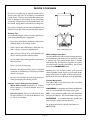
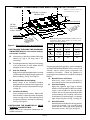
Care & Use Manual
and
Installation Instructions
for
Thermador® Glass Ceramic Gas
and
Glass Ceramic Dual Gas & Electric
Cooktops
Models:
CGX304 / CGX365 / CGX456
CD365 / CD456
A Special Message to Our Customers,
Thank you for buying a Thermador® cooktop. We hope that the information in this manual helps you easily operate and care for your cooktop for
years of satisfaction.
Please contact us if you have any questions or comments.
Sincerely,
Thermador Test Kitchen Consumer Scientists
TABLE OF CONTENTS
Gas Requirements ............................. 1
What To Do If You Smell Gas.......... 1
Important Safety Instructions ....... 2-3
Electrical Requirements .................... 4
Models and Parts Identification ................5-7
Cooktop Operating Instructions
Before Using the Cooktop
for the First Time .................................... 8
Electric Cooktop Operation ............. 8-9
Electric Control Knob ............................ 9
Signal Lights ............................................... 9
Gas Cooktop Operation............... 10-11
Gas Control Knobs .............................. 10
Cookware......................................... 12-13
Electric Cooking Chart ....................... 14
Gas Cooking Chart .............................. 15
Care and Maintenance
Ceramic Cooktop Cleaning
Guide ................................................. 16-17
Cleaners to Avoid ................................ 16
Daily Care Techniques ........................ 16
Special Care Techniques ..................... 17
Dual and All Gas Cooktop
Cleaning Guide ................................ 18-19
Where to Order Cooktop Cleaning
Creme® .............................................................................. 19
Installation Instructions ............. 20-24
Warranty .......................................... 25
Before Calling for Service .... Back Cover
How to Obtain Service ......... Back Cover
Packaged with Cooktop
Care and Use Manual plus Installation Instructions
Cooktop Cleaning Creme®
Razor Blade Scraper
Mounting Brackets
Registration Card
Foam Tape Seal
WARNINGS FOR SAFE GAS INSTALLATIONS
Installer: Please leave these instructions with the unit for the owner.
Owner: Please retain these instructions for future reference.
!
▲
WARNING: If the information in this manual is not followed exactly, a fire or
explosion may result causing property damage, personal injury or death.
AVERTISSEMENT
✓ Ne pas entreposer ni utiliser de
l‘essence ni d’autres vapeurs ou
liquides inflammables dans le
voisinage de l’appareil, ni de tout
autre appareil.
FOR YOUR SAFETY
✓ Do not store or use gasoline or
other flammable vapors and
liquids in the vicinity of this or
any other appliance.
S’IL Y A UNE ODEUR DE GAZ:
WHAT TO DO IF YOU SMELL GAS
•
Shut off gas to the appliance.
•
Coupez l’admission de gaz de l’appariel.
•
Extinguish any open flame.
•
Ènteindre toute flamme nue.
•
Open Lid.
•
Ouvrir le couvercle.
•
If odor continues, immediately phone your
gas supplier.
•
•
If you cannot reach your gas supplier, call
the fire department.
Si l’odeur peraiste, appeler immediatement
votre compagnie de gaz ou votre
departement des incendies.
Installation and service must be performed by a qualified installer,
service agency or the gas supplier.
PROPANE GAS INSTALLATION
The cooktop is ready for use with natural gas. It
may be converted for use with propane gas
using the Burner Propane Conversion Kit, Model
NLPKIT5, Part Number 35-00-622. A qualified
service techhnican or installer can convert the
cooktop. Be sure the unit being installed is
correct for the type of gas being used. Refer to
the Rating plate on the right side underneath
the cooktop, see pages 5 to 7 for the location.
CAUTION
!
▲
TESTED IN ACCORDANCE WITH ANS Z21.1a
1996 CURRENT ISSUE, STANDARD FOR
HOUSEHOLD COOKING GAS APPLIANCES, and
CAN/CGA 1.1 DOMESTIC GAS RANGES,
CURRENT ISSUE.
Check your local building codes for the proper method
of installation. In the absence of local codes this unit
should be installed in accordance with the National
Fuel Gas Code No. Z223.1 Current Issue and National
Electrical Code ANSI/NFPA No. 70 Current Issue or
the CAN - B149 Installation Codes for Gas Burning
Appliances and C22.1 Canadian Electrical Code Part 1.
When connecting the unit to propane gas, make certain the propane tank
is equipped with its own high pressure regulator. In addition, the pressure
regulator supplied with the cooktop must be on the inlet gas pipe of this
unit. The maximum gas pressure to this appliance is not to exceed 14.0
inches water column from the propane gas tank pressure regulator.
PAGE 1
SAFETY PRACTICES TO AVOID PERSONAL INJURY
!
▲
IMPORTANT SAFETY INSTRUCTIONS
READ ALL INSTRUCTIONS BEFORE USING YOUR COOKTOP
WARNING: IF THE INFORMATION IN THIS
MANUAL IS NOT FOLLOWED EXACTLY, A FIRE OR
EXPLOSION MAY RESULT CAUSING PROPERTY
DAMAGE, PERSONAL INJURY OR DEATH.
WARNING: TO REDUCE THE RISK OF FIRE,
ELECTRIC SHOCK, OR INJURY TO PERSONS,
OBSERVE THE FOLLOWING:
• DO NOT USE WATER, including wet dishcloths or
towels - a violent steam explosion will result.
• SMOTHER FLAMES from a grease fire with a closefitting lid, cookie sheet or other metal tray. Turn off
the gas burners or the electric elements. BE CAREFUL TO PREVENT BURNS. If the flames do not go
out immediately EVACUATE AND CALL THE FIRE
DEPARTMENT.
• Use baking soda to SMOTHER FLAMES from other
type food fires. Never use water on cooking fires.
• NEVER PICK UP A FLAMING PAN - You may be
burned.
• TURN OFF THE VENTILATOR in case fire or when
"flaming" liquor or other spirits. The blower could
spread the flames.
• ALWAYS HAVE A WORKING SMOKE DETECTOR NEAR THE KITCHEN.
• USE AN EXTINGUISHER ONLY IF:
1. You know you have a Class ABC extinguisher, and
you already know how to operate it.
2. The fire is small and contained in the area where it
started.
3. The fire department is being called.
4. You can fight fire with your back to an exit.
WARNING: TO REDUCE THE RISK OF FIRE, ELECTRIC SHOCK, OR INJURY TO PERSONS, OBSERVE THE FOLLOWING:
• Use this unit only in the manner intended by the
manufacturer. If you have any questions, contact the
manufacturer
!
▲
• Before servicing or cleaning unit, switch power off at
service panel and lock service panel to prevent power
from being switched on accidentally.
• Do not cook on a cooktop in which the glass top has
broken. If the cooktop glass should break, do not use
it or attempt to clean or fix it. Cleaning solutions and
spill-overs may penetrate the broken cooktop and
create a risk of electric shock. Turn off electric circuit
to the cooktop and call an authorized service agency
immediately.
• WARNING: DO NOT STORE ITEMS OF INTEREST
TO CHILDREN ABOVE THE COOKTOP OR AT
THE BACK OF IT. IF CHILDREN CLIMB ONTO
THE COOKTOP TO REACH THESE ITEMS, THEY
COULD BE SERIOUSLY INJURED.
• Children should not be left alone or unattended in an
area where appliances are in use. They should never
be allowed to sit or stand on any part of appliance.
WARNING: Do not store flammable materials on or
near the cooktop.
• When using the cooktop, do not touch the hot
cooking area or the immediate surrounding area.
Even though dark in color, these areas may be hot.
Areas adjacent to the elements may become hot
enough to cause burns.
• Never let clothing, pot holders, or other flammable
materials come in contact with the burners, burner
grates or cooking area until they are cool to the
touch.
• Use only dry pot holders. Moist or damp pot holders
on hot surfaces may cause burns from steam. Do not
use a towel or other bulky cloth in place of pot
holders. Do not let pot holders touch hot cooking
areas.
• Always use utensils that have flat bottoms and that
are large enough to cover the whole cooking area.
The use of a utensil smaller than the size of the
cooking area will expose a portion of the heated area
to direct contact with the user which could result in
burns.
• Always use cookware and utensils appropriate for
the type and amount of food being prepared.
PAGE 2
!
▲
IMPORTANT SAFETY INSTRUCTIONS
• Hold the handle of the pan to prevent movement of
the utensil when stirring or turning food. Turn
handles of utensils inward so that they do not extend
over adjacent work areas, cooking areas, or the edge
of the cooktop. This will help prevent hot food spills.
!
▲
• The cooktop is factory assembled for natural gas. It
should be correctly adjusted by a qualified service
person or installer for the type of gas with which it is
used. (See Page 1 for propane gas.)
• CAUTION: The cooktop is for cooking. Never use
it to warm or heat a room.
• For personal safety, wear proper apparel. Loose
fitting garments or hanging sleeves should never be
worn while cooking.
• Be sure your appliance is properly installed and
grounded by a qualified servicer in accordance with
the Installation Instructions provided with the cooktop.
• In the event that personal clothing catches fire,
DROP AND ROLL IMMEDIATELY to extinguish
flames.
• Do not repair or replace any part of the appliance
unless specifically recommended in this manual. All
other servicing should be referred to a qualified
servicer.
• Use high heat settings on the cooktop only when
necessary. Use low to medium settings to heat oil
slowly.
• Other than the use of metal pans, only certain types
of glass, heat-proof glass ceramic, ceramic, earthenware, or other glazed utensils are suitable for cooktop
use. These types of utensils may break with sudden
temperature changes. Use only on low or medium
heat settings according to the utensil manufacturer’s
directions.
• Clean the cooktop with caution. If the soil must be
removed while the cooktop is hot, clean the hot top
with the metal razor blade scraper only. Do not use
a wet sponge or cloth while it is hot. Some cleaners
produce noxious fumes if applied to a hot surface.
• Clean the ventilation system above or behind the
cooktop frequently, so that grease from the cooking
vapors does not accumulate on the filters, fan, intake,
or hood.
• For proper lighting and performance of the burners,
keep the igniters clean. It is necessary to clean these
when there is a boil over, or when the burner does
not light even though the electronic igniters click. See
Page 18.
• Do not use aluminum foil to line any part of the
cooktop. Improper use of a foil liner could result in
a shock, fire hazard or it could obstruct the flow of
combustion and ventilation air. Foil is an excellent
heat insulator and heat will be trapped beneath it.
This will upset the cooking performance and can
damage the cooktop finish.
• Do not heat unopened food containers; a buildup of
pressure may cause the container to burst.
• Never leave the burners unattended when using high
flame settings. Boilovers cause smoking, and greasy
spillovers that may ignite. More importantly, if the
flame is smothered, unburned gas will be coming into
the room. See “What To Do If You Smell Gas”, Page
1.
• During cooking, set the burner control so that the
flame heats only the bottom of the pan and does not
extend beyond the edge of the pan.
• If the cooktop is near a window, be certain the
curtains do not blow over or near the burners; they
could catch on fire.
• Take care that drafts, like those from fans or forced
air vents, do not blow flammable material toward the
flames or push the flames so that they extend beyond
the edges of the utensil.
• In the event a burner goes out and gas escapes, turn
OFF all the controls and open a window or a door.
Do not attempt to use the cooktop until the gas has
had time to dissipate. Wait at least 5 minutes before
using the cooktop.
PAGE 3
ELECTRICAL REQUIREMENTS AND GROUNDING INSTRUCTIONS
PLEASE READ CAREFULLY
See Installation Instructions for electrical requirements and grounding instructions, Page 24.
MODELS:
CGX304U
CGX365U
CGX456U
Ratings see back cover
FOR PERSONAL SAFETY, THIS APPLIANCE
MUST BE PROPERLY GROUNDED.
DO NOT UNDER ANY CIRCUMSTANCES
CUT OR REMOVE THE THIRD (GROUND)
PRONG FROM THE POWER CORD PLUG.
ALWAYS DISCONNECT THE ELECTRICAL
PLUG FROM THE WALL RECEPTACLE
BEFORE SERVICING THIS UNIT.
If the electrical outlet you intend to use does not accept
the 3-prong plug, it is the personal responsibility and
obligation of you, the user, to have it replaced with a
properly grounded 3-prong wall receptacle in accordance
with the National Electrical Code and/or applicable local
codes and ordinances, by a qualified electrician.
!
▲
Cooktop
➛
The power cord on your cooktop is equipped with a
three prong grounding plug with polarized parallel
blades. This type of plug is for your protection against
shock hazard. This cord must be plugged directly into a
properly grounded 3-prong wall receptacle that is connected to a correctly polarized 120 volt electric power
supply. It is recommended that a separate circuit
serving each appliance be provided.
CAUTION - ALL MODELS
In Case of an Electrical Failure
If for any reason a gas control knob is turned ON and
there is no electric power to operate the electronic
igniter of the cooktop, turn OFF all the gas control
knobs and wait 5 minutes for the gas to dissipate
before lighting the burner manually. On all models
only the standard burners can be turned on
manually.
To light the burners manually, carefully hold a lighted
match to the burner ports and push and turn the gas
control knob to HI until it lights and then turn knob to
desired setting. During a power failure you can use the
standard cooktop burners, but each must be lit with a
match. The ExtraLow® burners can not be used
during a power failure. Refer to pages 5 through 7
and 11 for more information.
PAGE 4
Three
Prong
Plug
➛
MODELS:
CD365U
CD456U
Ratings see back cover
Outlet
MODEL and PARTS IDENTIFICATION
Model CD456U
9
1
2
8
1
3
5
3
4
HOT
6
5
2
4
6
HOT
➚
7
Model CD365U
9
1
2
5
8
12
11
10
HOT
1
3
6
2
HOT
5
10
6
11
1.
1300 to 9100 BTU/HR Burner & Control Knob
2.
1650 to 11,000 BTU/HR Burner & Control Knob
3.
1650 to 11,000 BTU/HR Burner & Control Knob
4.
1300 to 9100 BTU/HR Burner & Control Knob
5.
Dual-Circuit Element: Small 6"–1000 Watt,
Large 9" – 2200 Watt Element & Control Knob
7
➚
3
12
6.
Dual-Circuit Element: Small 5" –800 Watt,
Large 7" – 1700 Watt Element & Control Knob
7.
"ON" Light
8.
"Hot" Indicator Lights
9.
Grates
10. Burner Cap
11. Burner Plate
12. Rating Plate, right side, underneath cooktop
PAGE 5
MODEL and PARTS IDENTIFICATION
Model CGX304U
Models CGX365U
Models CGX456U
Page 6
MODEL and PARTS IDENTIFICATION
Model CGX304U
1. ExtraLow® 365 to 11,000 BTU/HR Burner &
Control Knob
6. Grate
7. Burner Cap
2. ExtraLow® 300 to 9100 BTU/HR Burner &
Control Knob
8. Burner Plate
3. 1300 to 9100 BTU/HR Burner & Control Knob
9. Rating Plate, right side,
underneath cooktop
4. 1650 to 11,000 BTU/HR Burner & Control Knob
5. "ON" Light
Models CGX365U
1. 1300 to 9100 BTU/HR Burner &
Control Knob
6. "ON" Light
7. Grate
2. ExtraLow® 365 to 11,000 BTU/
HR Burner & Control Knob
3. ExtraLow® 300 to 9100 BTU/HR
Burner & Control Knob
4. 1300 to 9100 BTU/HR Burner &
Control Knob
8. Burner Cap
9. Burner Plate
10. Rating Plate, Right Side,
Underneath Cooktop
5. 1650 to 11,000 BTU/HR Burner &
Control Knob
Models CGX456U
1. 1300 to 9100 BTU/HR Burner &
Control Knob
6. 1650 to 11,000 BTU/HR Burner &
Control Knob
2. 1650 to 11,000 BTU/HR Burner &
Control Knob
7. "ON" Light
8. Grate
3. ExtraLow® 365 to 11,000 BTU/
HR Burner & Control Knob
4. ExtraLow® 300 to 9100 BTU/HR
Burner & Control Knob
5. 1300 to 9100 BTU/HR Burner &
Control Knob
9. Burner Cap
10. Burner Plate
11. Rating Plate, Right Side,
Underneath Cooktop
Page 7
ELECTRIC COOKTOP OPERATION
BEFORE USING THE COOKTOP FOR THE
FIRST TIME:
• Remove all packing materials and literature from the
cooktop surface. Read all safety precautions and
care & use information prior to operating.
ELEMENTS
When either element is turned on the "ON" signal light
turns red; when both elements are turned off, the
“ON” signal light goes out.
outer
• While cool, wipe with a clean, damp sponge and dry.
• Apply the Cooktop Cleaning Creme® packaged
with the cooktop. Buff with a clean cloth. This helps
protect the surface and makes cleanup easier. See
Page 16 for daily care instructions.
• There may be a slight odor during the first several
uses; this is normal and will disappear.
• Optimum cooking results depend on the proper
cookware being selected and used. See Pages 12-13.
• The cooking surface will hold the heat and remain
hot up to 25 or 30 minutes after the elements have
been turned off. See Hot Surface Indicator lights on
Page 9.
Precautions for Long Life and Good Appearance
of the Surface:
• Regular, daily care using the Cooktop Cleaning
Creme will protect the surface and make it easier to
remove food soil and water spots.
• The glass ceramic cooking surface is a durable material that is resistant to impact but is not unbreakable
if a pan or other object is dropped on it.
inner
Dual Radiant Elements (Models CD365 & CD456)
This type of electric element has two cooking sizes.
Select either the small inner element or both the inner
and outer elements, (dual) depending of the base size of
your pan.
TEMPERATURE LIMITERS
Each radiant heating element has its own sensor to
protect the glass cooking surface from extreme high
temperatures. The limiters will operate automatically
by cycling the element off regardless of the knob setting.
Although cycling is normal, any one of the following
conditions can activate the limiter and cause it to cycle
on and off more than usual:
• Do not use aluminum foil directly on the glass; it will
melt and permanently damage the glass surface.
• The base of the pan is not making full contact with the
heating surface (due to a warped or uneven base).
• Do not allow plastic, paper, or cloth to come in
contact with the hot glass surface; these items can
melt or burn and can damage the glass surface.
• The pan base is too small for the size of the element.
• Do not allow pans to boil dry. This can permanently
damage the pan, element and/or the cooktop.
• The pan has boiled dry.
• The material or shape of the pan is slow to transfer
the heat.
• No pan has been placed on the element.
• Use only flat bottom pans. (See Page 12).
• Never cook food directly on the glass.
• Do not use the glass surface as a cutting board.
• Do not slide cookware across the cooking surface;
it may scratch the glass. Even cookware with smooth
bases may scratch, if grit gets between the pan and
the surface.
Page 8
ELECTRIC COOKTOP OPERATION
CONTROL KNOBS
The placement of each knob corresponds to the placement of the heating element that it controls. To turn
on any element, PUSH DOWN on the knob and TURN
in either direction to the desired heat setting.
RETAINED HEAT
The glass cooking surface retains heat and stays hot
after the element(s) have been turned off. The retained
heat may be used to hold foods at serving temperatures
for a short time.
There are an infinite number of heat settings
between the LO and HI positions. Detents (fixed
positions) are found at LO and HI to define minimum
and maximum heat settings. The LO setting provides a
very low heat for simmering foods such as spaghetti
sauce and cooking Hollandaise sauce. With the option
of using either gas and electric, you can move a pan from
gas to electric (LO) for an even lower heat setting.
Hot Surface Indicator Lights
"ON" Indicator
Light
SIGNAL LIGHTS
Element “ON” Signal Light
The element “ON” signal light glows whenever any
element is turned on. The light remains lit until all of the
elements are turned off.
The “ON” light is located on the right side and below
the control knobs.
When the elements are turned on, a red glow can be
seen through the glass. The elements cycle on and off
to keep the selected heat setting. Poor cookware
causes the element to cycle on and off more often. (See
Temperature Limiters on Page 8).
To turn ON the small, inner element only, press
down on the control knob and turn it clockwise to a
heat setting.
To turn ON both inner and outer elements
together, press down on the control knob and turn it
counterclockwise to a heat setting.
HOT SURFACE INDICATOR LIGHTS
Whenever a cooking surface is too hot to touch, an
indicator light will turn on automatically in the area
marked Hot Surface. The light remains on until the
cooking area has cooled to a safe-to-touch temperature. There is one Hot Surface Indicator light for each
electric heating element.
If a Hot Surface Indicator light is on, use caution when
working or cleaning around the cooktop.
The element is in the off position when the indicator on
the knob lines up with the word “OFF” and snaps into
place. Align the indicator with the LO position. The dual
element symbol and the inner element symbol ● are
not heat settings.
●
Page 9
GAS COOKTOP OPERATION
• The burner flame will pulse ON and OFF when the
setting is at any position between LO and XLO.
GAS CONTROL KNOB SETTINGS
OFF
• The length of time the flame is ON and OFF varies.
• With a setting just below LO, the flame will be ON
approximately 53 seconds and OFF 7 seconds of each
minute.
HI
LO
STANDARD BURNER
(All Models)
All standard burner controls press down to turn and
have an infinite number of heat settings. There are no
fixed positions. Select the appropriate control knob,
press down and turn it counterclockwise to the HI
position (detent) until the burner lights. Adjust the
flame size. Turn off by turning the control clockwise to
OFF.
OFF
• With a setting at the XLO position, the flame is ON
approximately 7 seconds and OFF 53 seconds of each
minute.
FOR THE BEST RESULTS
• Temperature control will be more accurate if a lid is
used.
• Bring food to a rolling boil; stir well to be sure all the
food is boiling; cover and reduce the heat to just
below LO.
• Check periodically to see if the control knob should
be turned to a lower setting.
• Adjust control knob to lower settings in small steps.
HI
• If control is set too low to maintain simmer, bring the
food back to a boil before setting a higher simmer
setting.
XLO
LO
WHAT TO EXPECT WHEN USING XLO
EXTRALOW®
(CGX Models Only)
All ExtraLow controls press down to turn and have an
infinite number of heat settings. There are no fixed
positions. The ExtraLow settings are located after LO
and before XLO®, at the detent, shown by the broken
line.
The XLO setting on the right front and right rear
burners (CGX304), and the center front and center
rear burners (CGX365 and CGX456) are designed to
provide flame settings which enable you to simmer,
poach, melt and hold cooked food at a serving temperature, without scorching or burning. This is accomplished because the XLO setting cycles the flame OFF
and ON for varying lengths of time.
HOW THEY WORK
• The BTU/HR usage on the 9,100 BTU/HR burner
ranges from HI (at 9100) to XLO (at 300). The
BTU/HR usage on the 11,000 BTU/HR burner ranges
from HI (at 11,000) to XLO (at 365).
• There are an infinite number of settings between HI
and XLO; the control knob can be set at any
position.
• The type and quantity of the food will affect which
setting to use.
• The size, type and material of your pan will affect
which setting to use.
• When a large pan is used on a small burner, it may
cause the simmer action to occur mainly in the center
of the pan. When the food is stirred, the cooler food
near the edges of the pan may result in an overall
temperature too cool to simmer. If this happens, turn
the burner up slightly.
• It is normal to stir food occasionally. This is especially
important when simmering for several hours. For
example: homemade spaghetti sauce or beans.
• It is normal not to see simmer bubbles immediately
after the food has been stirred.
• While the flame is ON there may be bubbling; there
should be at least steam and a slight quivering of the
liquid’s surface.
• Simmer bubbles may not be seen when the flame has
cycled OFF. (Models CGX)
Page 10
GAS COOKTOP OPERATION
COOKTOP PARTS
IGNITERS
FOR PROPER COMBUSTION DO NOT
USE THE COOKTOP WITHOUT THE
BURNER GRATES IN PLACE .
Each five finger grate is porcelain enameled cast iron
and has five (5) prongs. These prongs fit into the five
(5) indentations on the burner plate below.
The cooktop uses electronic igniters to
light the burners. Each burner has its
own igniter that sparks when any burner
is turned on. When the igniters are
clicking (sparking), do not touch the
burners. If a burner fails to ignite, see “Before Calling
For Service,” inside back cover.
GRATES
AUTOMATIC RE-IGNITION
If any burner flame blows out, the electronic igniter
automatically sparks on all burners to relight the flame.
!
▲
Prongs
WARNING Do not clean or touch any of the
burners when one or both XLO® burners are in use.
When the XLO burner automatically reignites, the
igniters at all the burners will spark.
(Underside)
POWER FAILURE
BURNER CAP
In the event of a power failure, each standard burner can
be manually lighted separately. The two ExtraLow®
burners cannot be used during a power failure.
A Tab
If the cooktop is being used when the power failure
occurs, turn all the burner control knobs to the OFF
position. Then, the standard burners can be lighted by
holding a match at the ports and turning the control
knob to the HI position. Wait until the flame is burning
all the way around the burner cap before adjusting the
flame to the desired height.
D
Gas Port
(Underside)
BURNER BASE
Indentations
Be sure to turn the ExtraLow burners OFF if a power
failure occurs, as they will not turn back on until both
control knobs are turned OFF first. See “What To Do
If You Smell Gas,” Page 1.
Igniter
C
BURNER EFFICIENCY and
FLAME CHARACTERISTICS
B Notch
The Burner Cap is porcelain enamel and has a tab (A) on
the underside that fits into the notch (B) on the burner
base (C). The circle of gas ports are located under the
burner cap. If these ports (D) are clogged, use a wire,
a straightened paper clip or a needle to clear the ports.
Do not use a toothpick; it could break off inside the port.
If the condition persists, contact a service agency for
adjustment.
The burner flame should be blue in color and stable with
no yellow tips, excessive noise or fluttering. It should
burn completely around the burner cap.
Foreign particles in the gas line may cause an orange
flame during initial use. This should disappear with use.
If the flame does not burn evenly all the way around the
burner cap, be sure the cap is resting correctly on the
burner base and the gas ports are dry.
The burner should light in 4 seconds or less. If a
burner does not light, check to see that the cap is resting
correctly on the burner base.
Page 11
PROPER COOKWARE
CHARACTERISTICS OF A GOOD PAN
The choice of pans directly affects the cooking speed
and uniformity. For best results select pans with the
following features:
FLAT BASES - Check flatness of pan with a straight
edge. When pan is hot, the base (pan bottom)
should rest evenly on the surface without wobbling.
•
To check flatness on the electric surface, put one
inch of water in a pan. Turn control to HI and
observe the bubble formation in the bottom of the
pan. Flat pan bases have an even distribution of
bubbles. Bubbles forming in one or two areas show
uneven pan contact and uneven heat conduction.
Balanced Pan
PAN MATERIAL and WEIGHT - Medium to heavy
weight metal pans, with copper or aluminum disc
bottoms, conduct heat well. On the glass surface
they may leave residues which look like scratches;
clean immediately to remove. Medium to heavy
weight pans distribute heat more evenly and resist
warping. To prevent warping, cool pans slowly so
they will stay flat.
DIAMETER - The base of the pan should cover or
match the diameter of the electric element or flame
size. Pans may overhang the element area no more
than 1" all around. On a gas burner, the flames
should hit only the bottom of the pan.
Convex (rounded)
Concave (hollow)
PLACEMENT - Center the pan on the burner grate or
electric element before turning the unit on.
SIZE - Use cookware that is large enough to accommodate the amount of food or liquid to eliminate the
possibility of boilovers and spattering.
Flame Too Large for Pan Size
Use Lids that fit Properly
TIGHT FITTING LID - A lid shortens cooking time
by holding the heat inside the pan.
Do not use cookware with these characteristics:
• Thin bottom
• Concave bottom when heated
• Convex bottom when heated
• Poor balance (rocks back from weight of handle)
!
▲
•
Unbalanced Pan
!
▲
•
Plastic, paper and cloth can melt or burn
when in contact with a hot surface or burner grate.
Do not let these items come in contact with the
burner grate or electric element cooking surface.
•
Do not allow pans to boil dry. This can permanently damage the pan, the element, the burner
grate, the cooktop glass and/or the burner plate.
CAUTION
Foods packaged in aluminum foil should not
be placed directly on the glass ceramic surface or
burner grate for cooking; aluminum foil can melt to
either surface and cause permanent damage.
CAUTION
Page 12
PROPER COOKWARE
Do not use unusually large or warped utensils such as
canners and stock pots on HI heat for an extended
period of time. This may cause heat build up which can
result in damage to the cooktop or the surrounding
countertop. Once food has reached temperature, turn
the control setting down to maintain the cooking heat.
Use canners and stock pots that have a flat bottom and
extend no more than 2 inches beyond the burner grate.
Canning Tips:
An oversize canning pot can be used on the gas burners
with success following these suggestions:
•
Use a canner with a dark or dull finish to reduce heat
reflecting back to the cooktop surface.
•
Select a canner with a flat bottom, rather than one
with a concave, convex or rippled bottom.
•
Allow at least 3/8 inch of air space between the
canner overhang and the cooktop surface.
•
Use the lowest heat setting possible to maintain a
boil or pressure.
•
Be sure to cover all containers.
•
Follow the canning instructions given in a standard
cookbook or manufacturer’s instructions provided
with the canning jars.
•
Use care to prevent burns from the large amount of
steam generated by the canning process.
Look for canners fitting this description:
• Water Bath Canner: Standard 21 to 22-quart
canners with an 11 to 12-inch diameter and a 9 to
11-inch depth.
•
Pressure Canner: Canners vary in size from 8 to
22 quarts with 8 to 11-inch bottom diameters and
a 6-1/2 to 12-inch depth.
Large or Warped Utensils
Woks and Speciality Pans
Use only a flat bottom wok on electric heating elements.
A round bottom wok can be used on the burners with
a support ring. The round bottom wok is unstable
without the ring. Check that the ring does not restrict
air to the burners causing a yellow flame. See Custom
Accessories AWOKRING below.
Specialty pans such as woks, lobster pots, pressure
cookers, griddles, French fryers, etc. must meet similar
design requirements as regular cookware: flat bottom,
balanced, correct size, and proper cover (if applicable).
Custom Accessories
Thermador® offers several accessories for use on dual
or gas burner cooktops.
AWOKRING - a ring designed to hold a round bottom
wok. It is custom fitted to the shape of the grate.
GG1 - a cast aluminum griddle with a non-stick finish
that spans two burners. It is custom fitted to the grates.
AEGRIDDLE - an anodized aluminum griddle that
spans two glass ceramic electric elements.
For product information, call your local dealer or
800/735-4328
Page 13
ELECTRIC COOKING CHART
FOOD
BREADS
French Toast, Pancakes,
Grilled Sandwiches
START COOKING
CONTINUE COOKING
5 to 6
3 to 4
CEREALS
Cornmeal, Grits,
Oatmeal
H1
3-1/2 to 5
CHOCOLATE
LO
EGGS
Cooked in Shell
Fried, Scrambled
Hl
LO
5 to 6
2 to 3
5 to 6
5 to 6
Hl
5 or 6
3 to 4
LO
LO
3 to 4
5 to 6
3 to 4
Hl
LO to 2
5 to 6
3 to 4
POPCORN
6 to H1
2 to 3
PRESSURE COOKER
Meat,Vegetables
Hl
LO
Hl
LO
6 to Hl
LO to 2
3 to 4
LO to 2
4to 5
LO to 2
STIR FRY (Flat bottom WOK)
H1
5 to 6
VEGETABLES
Dried (i.e. beans)
Fresh
Grilled/ Sauted
Hl
HI
5 to 6
LO
LO
4 to 6
MEAT, FISH, POULTRY
Bacon, Sausage Patties
Braising: Swiss Steak,
Pot Roast
Frying: Chicl<en
Pan Frying: Lamb Chops,
Thin Steaks, Hamburgers,
Link Sausage
Simmering: Stewed
Chicken, Corned Beef
Poaching: Fish
RICE
SAUCES
Tomato Base
White, Cream, Bernaise,
Hollandaise
SOUPS, STEWS
Page 14
GAS COOKING CHART
Food
Start Cooking
Continue Cooking
Standard Burners
BREADS
French Toast, Pancakes,
Grilled Sandwiches
Med. - preheat skillet
Med. Lo to Med.
cook
Use standard
burner setting
CEREALS
Cornmeal, Grits,
Oatmeal
HI - cover, bring water
to a boil, add cereal
Med. Lo to Med.finish cooking according
to package directions
I to XLO® - to hold,
cover*
CHOCOLATE
LO to melt*
Remove when melted
2 to XLO - allow 10 to
1 5 minutes to melt.
I to XLO - to hold*
EGGS
Cooked in Shell
HI - cover, bring
water to a boil, add
eggs, cover
OFF to LO - cook 3 to
4 minutes for soft cooked;
or 15 to 20 minutes
for hard cooked
1 to XLO - cook 3 to 4
minutes for hard cooked;
15 to 20 minutes
for hard cooked
Fried, Scrambled
Med. to Med. Hi melt butter, add egg
LO to Med. Lo finish cooking
I to XLO - to hold for
a short period*
Med. - until meat starts
to sizzle
HI - melt fat, then
brown on Med. HI to
HI, add liquid, cover
Med. Lo - to
finish cooking
LO - cover,
simmer until tender
Use standard
burner setting
3 to I - simmer until
tender
Frying: Chicken
HI - melt fat, then
brown on Med.
LO - cover, finish
cooking
Use standard
burner setting
Pan Frying: Lamb Chops,
Thin Steaks, Hamburgers,
Link Sausage
Med. Hi to HIpreheat skillet
Med. to Hibrown meat
4 to 3 - hold, uncovered
3 to 2 - hold, covered
Simmering: Stewed
Chicken, Corned Beef,
Poaching Fish
HI- cover, bring liquid
to a boil
LO to Med. Lo - simmer
slowly
4 to I - simmer slowly
MEAT, FISH, POULTRY
Bacon, Sausage Patties
Braising: Swiss Steak,
Pot Roast
or
Continue Cooking
Extra Low®, Burners
(CGX models only)
POPCORN
Med to Med-HI - cover, heat Med. to Med. Hiuntil kernels start to pop
finish popping
Use standard
burner setting
PRESSURE COOKER
Meat, Vegetables
Med. Hi to HI- build
up pressure
Med. Lo to Med. maintain pressure
Use standard
burner setting
RICE
HI- cover, bring water to
boil, add rice, cover
LO - cover,
cook according to
package directions
4 to 2 - cook according
to package directions
I to XLO - hold, cover
SAUCES
Tomato Base
Med. Hi to HI- cook
meat/vegetables,
follow recipe
Lo to Med. Lo - melt fat,
follow recipe
LO
2 to XLO - simmer*
(2 to 3 to thicken sauce,
uncovered)
I to XLO - to hold,
cover*
White, Cream, Bernaise,
Hollandaise
LO to Med. Lo finish cooking
SOUPS, STEWS
HI - cover, bring
liquid to a boil
LO to Med. Lo - simmer
3 to 2 - simmer* I to
XLO - to hold, cover*
STIR FRY
HI - heat oil, add
vegetables
Med. Hi to HIfinish cooking
Use standard
burner setting
VEGETABLES
Fresh
Grilled, Sauted
HI - cover, bring water
and vegetable to a boil
HI
LO
I to XLO - to hold, cover*
Med.
* Stir occasionally
Page 15
CERAMIC COOKTOP CLEANING GUIDE
Care is easy on a daily basis when preventative steps
are taken. Apply only a small amount of Cooktop
Cleaning Creme® to a clean paper towel or cloth.
This provides a protective film that makes it easy to
remove water spots or food spatters.
The temperature of the cooking surface during use
reduces the protective qualities of the Cleaning Creme,
so it must be re-applied regularly to maintain the
appearance of the cooktop.
CLEANERS / PRODUCTS TO USE ON THE CERAMIC
SURFACE
Cooktop Cleaning Creme (incl. with cooktop)
Bon Ami®
Soft Scrub®, except on trim frame.
Vinegar (rinse and dry)
CLEANERS TO AVOID ON THE GLASS CERAMIC
SURFACE AND METAL TRIM FRAME: Use of these
types of cleaners may cause discoloration and permanent
damage.
•
Glass cleaners: Do not use glass cleaners containing
ammonia or chlorine bleach. These ingredients may
etch or stain the cooktop.
•
Caustic cleaners: Oven cleaners such as Easy Off®
or Dow® may etch the cooktop surface.
•
Abrasive cleaners: Metal scouring pads such as
Chore Girl® and Kurly Kate® and scrub sponges
such as Scotch Brite® can scratch the cooktop and
leave metal marks.
Soap-filled scouring pads such as Rescue® or S.O.S.®
can scratch the cooktop surface.
Clean cloth, paper towel or sponge
Razor blade scraper (packaged with range)
Non-metal Scouring Pads:
Dobie®, Scruffy®, Tuffy®
CLEAN CARE TECHNIQUES (FOR MOST SOILS)
1. Clean the surface when it is completely cool,
with the exception of spills containing milk, dry
sugar, sugar syrup, or tomato described in the
Special Care Techniques on the following page.
These must be removed IMMEDIATELY.
CAUTION: DO NOT use any kind of cleaner on
the glass while the cooktop is hot. The resulting
fumes can be hazardous to your health. The heated
cleaner can chemically attack and damage the
cooktop.
•
Powdery cleaners that contain chlorine bleach can
stain the cooktop.
•
Cleaners that are flammable may be dangerous
2. Cooktop surface, glass-ceramic: Wipe off greasy
spatters with a clean, damp sponge, cloth or paper
towel. Rinse and dry. Use vinegar if smudge
remains. Apply Cleaning Creme as directed above.
Rub on the cooktop surface. When dry, buff surface
with clean paper towel or cloth.
3. Knobs, plastic: Pull up to remove. Wipe with hot
soapy sponge; rinse and dry. Do not soak.
4. Trim Frame, enamel paint on stainless steel:
Wipe with hot, soapy sponge; rinse and dry. Do not
use steel wool pads and / or powdered cleansers,
The paint could be scratched or marred.
How to Use Razor Blade Scraper
Use Daily
Page 16
GLASS CERAMIC COOKTOP CLEANING GUIDE
CD365U Model Shown
SPECIAL CARE TECHNIQUES
TYPE OF SOIL
POSSIBLE SOLUTION
Dry sugar, sugar syrup, milk or tomato spills.
Melted plastic film or foil. All these items
REQUIRE IMMEDIATE REMOVAL. Remove only
these types of spills while the surface is hot using the
razor blade scraper. See Page illustration on page16.
Failure to remove these soils immediatly can
permanently damage the surface.
• Remove pan and turn off the element.
• Angle the scraper slightly, using care not to gouge or
scratch the glass. Push soil off the heated area.
• After the surface has cooled, remove the residue and
apply the Cooktop Cleaning Creme®.
• Soften by laying a damp paper towel or sponge on top
of soil for about 30 minutes.
• Use non-metal scouring pad such as Dobie® with Soft
Scrub®, or use the razor blade scraper. Rinse and dry.
Recondition with Cooktop Cleaning Creme and a
clean cloth or paper towel.
Burned-on food soil, dark streaks, and specks
• Use vinegar or a soapy sponge to remove grease; rinse
thoroughly and dry. Apply Cooktop Cleaning Creme.
• Pans with aluminum, copper or stainless steel bases
may leave marks. Treat immediately, after surface has
cooled, with the Cooktop Cleaning Creme. If this
does not remove the metal marks, try a mild abrasive
(Bon Ami®, Soft Scrub®) with a dampened paper
towel; rinse; and re-apply creme.
Failure to remove metal marks before the next
heating makes removal difficult.
Greasy spatters
Metal marks
Hard water spots
Hot cooking liquids dripped on surface
• The minerals in some water can be transferred onto
the surface and cause stains. Use undiluted white
vinegar, rinse and dry. Recondition with Cooktop
Cleaning Creme.
Remove boil-overs / stains, before using the cooktop again.
Surface scratches:
Small scratches are to be expected on the glass surface
, but do not affect cooking. Although scratches are not
removable, in time they will become smoother and
much less noticeable with daily use of the Cooktop
Cleaning Creme.
• Can be reduced by removing sand-like grains/grit such
as salt and seasoning from below the pan.
• Can be reduced by using pans with bases that are
smooth, clean, and dry before use. Use recommended
Cooktop Cleaning Creme daily on the cooktop.
CAUTION: Diamond rings will scratch the surface.
Page 17
DUAL and ALL GAS COOKTOP CLEANING GUIDE
The entire Cooktop can be safely cleaned by wiping with clean warm water and a clean sponge, then drying. If
stubborn soil remains, follow the recommended cleaning methods below.
C
G
D
C
B
F
A
D or E
(CGX365U Model Shown)
•
•
•
•
•
•
G
Do not clean any part of the cooktop surface when any element or burner is on.
Always use the mildest cleaner that will do the job. Use clean, soft cloths, sponges or paper towels.
Rub stainless steel finishes in the direction of the grain. Wipe area dry to avoid water marks.
Before cleaning, be certain the burners are turned off and the grates are cool.
Do not clean removable cooktop parts in any self-cleaning oven.
After cleaning, place all parts in their proper positions before using cooktop.
The cleaners recommended below indicate a type and do not constitute an endorsement. Use all
products according to package directions.
A
Aluminum
Alloy –
Burner Base
Clean and polish with RevereWare® Metal Polish following package directions.
Use Brillo® or S.O.S.® pads to clean. Rub lightly, in a circular motion, rinse and dry.
Aluminum cleaners may dull the surface.
B
Ceramic
Igniter
Carefully wipe with a dampened cotton swab or gently scrape with a toothpick. Avoid
excess water on the igniter as it will cause excessive sparking until they dry.
Remove any lint that may remain on the igniter after cleaning.
C
Plastic
Control
Knob/
Nameplate
All burner control knobs should be in the OFF position before cleaning. Lift off and
wipe with a sudsy sponge. Rinse and dry. Do not soak or wash in the dishwasher.
For removal, lift up. The Thermador® nameplate is not removable.
D
Porcelain
Enamel
Do not let acid spills like milk, wine, tomatoes or fruit juices remain on porcelain
surface. Wipe up immediately using a dry towel. Do not use a moistened sponge/towel
on hot porcelain.
Trim Frame
• Light soil, not cooked on – Hot water and mild detergent, Cooktop Cleaning Creme®.
Avoid cleaners listeds on Page 16.
Burner Caps,
Grates and
Plates
DO NOT SOAK CAPS.
• Moderate soil, cooked on – Cooktop Cleaning Creme, Soft Scrub®.
• Heavy soil, cooked on – Brillo or S.O.S. (fresh pad).
Grates Only
• Very heavy soil, cooked on - Easy Off Fume Free, MAX® (cold formula). It is normal for
grates to craze (hairlike lines) and blister with age because of closeness to high
temperatures and soils.
DUAL and ALL GAS COOKTOP CLEANING GUIDE
(Continued)
E
Stainless
Steel
Trim Frame
Always wipe or rub with grain. Clean with a soapy sponge; rinse and dry. Or wipe with
Fantastic® or Formula 409® sprayed onto a paper towel. Polish with Revere Ware®
Metal Polish or Stainless Steel Magic® and a soft cloth. Remove water spots with a cloth
dampened with white vinegar.
F
Cooktop Seal
To loosen soil, lay a dampened cloth on seal for a few minutes. Then wipe clean. A mild
detergent can be used. DO NOT use any sharp object on the seal; it will cut or
permanently damage it.
G
Rubber
Gasket
Remove knob. Pull gasket toward stem and lift out. Wash with mild detergent and hot
water; rinse and dry. Replace gasket by fitting groove around opening. The top will not
be flush with the glass surface.
Where to order Cooktop Cleaning Creme®
Thermador® recommends any Cooktop Cleaning
Creme made for glass ceramic cooktops. To
purchase additional supplies of Cooktop Cleaning
Creme, phone your nearest parts distributor or
(800) 735-4328.
Page 19
INSTALLATION INSTRUCTIONS
GLASS CERAMIC GAS & GLASS CERAMIC DUAL GAS AND ELECTRICS COOKTOPS
30" MODELS: CGX304U
36" MODELS: CGX365U / CD365U
45" MODELS: CGX456U / CD456U
PLEASE READ ENTIRE INSTRUCTIONS BEFORE PROCEEDING
IMPORTANT: Save these instructions for the local electrical inspector’s use.
INSTALLER: Please leave these Installation Instructions with this unit for the owner.
OWNER: Please retain these instructions for future reference.
POWER REQUIREMENTS & GROUNDING
TABLE OF CONTENTS
Safety Instructions ....................................................................... 20
Power Requirements and Grounding ..................................... 20
Gas Pressure and Propane Installation ................................... 20
Cabinet Considerations and Cutout ................................. 21-22
Installing the Cooktop .......................................................... 22-23
Connecting Gas ........................................................................... 23
Connecting Electrical Supply ..................................................... 24
Final Check.................................................................................... 24
Before First Use ........................................................................... 24
Warranty ....................................................................................... 25
IMPORTANT SAFETY INSTRUCTIONS
•
Installation must conform with local codes or, in the
absence of local codes, with the National Fuel Gas
Code, ANSI Z223.1.
•
The appliance must be electrically grounded in
accordance with local codes or, in the absence of
local codes, with the National Electrical Code,
ANSI/NFPA 70-1990. (In Canada, installation must
be in accordance with the CAN 1-B149.1 and .2
Installation Codes for Gas Burning Appliances and/
or local codes.)
•
This appliance has been tested in accordance with
ANS Z21.1 - 1996, Standard for Household Cooking
Appliances (USA) and in accordance with CAN1.1M81 Interim Reqt #58 Domestic Gas Cooktops
(CANADA).
!
▲
WARNING: Improper installation, adjustment,
alteration, service or maintenance can cause
injury or property damage. Refer to this manual.
For assistance or additional information consult
a qualified installer, authorized service agency,
manufacturer or the gas supplier.
•
This appliance is equipped with an intermittent/
interrupted ignition device.
•
The cooktop should be used in conjunction with a
suitable ventilation system. Either a Thermador
overhead or down-draft system is suggested.
CGX MODELS:
Power Supply: 120 VAC, 15 or 20 Amp. Circuit, 50/60 Hz.
2-wire grounded outlet. For appliance rating See back cover.
This appliance is factory-equipped with a 5-foot power
supply cord with a 3-prong grounding plug (with polarized
parallel blades). THE THIRD GROUND PRONG
SHOULD NOT, UNDER ANY CIRCUM–
STANCES, BE CUT OR REMOVED. IT MUST BE
PLUGGED INTO A MATING GROUNDING TYPE
RECEPTACLE, CON-NECTED TO A CORRECTLY
POLARIZED 120 VOLT CIRCUIT. A separate circuit is
recommended. If there is any doubt as to whether the
wall receptacle is properly grounded, the customer
should have it checked by a qualified electrician.
! cord, be sure all controls are in the OFF position.
▲
WARNING: Before you plug in electrical
POWER REQUIREMENTS & GROUNDING CD
MODELS:
Power Supply: 120 /208 VAC, 15 or 20 Amp. Circuit,
50/60 Hz., 3 wire. 120/240 VAC, 20 Amp. Circuit, 50/60
Hz. 3-wire grounded outlet. For appliance rating, see
back cover. Install junction box (not furnished) below
countertop within 3 feet of flexible conduit (supplied)
located at center rear of cooktop. Junction box must be
accessible from front of cabinet. If cooktop is installed
over an oven, see oven installation instructions.
Supply Pressure
Natural Gas - 6 inches water column minimum.
Propane Gas - 11 inches water column minimum.
Propane Gas Installation
The propane gas tank must be equipped with its own
high pressure regulator in addition to the pressure
regulator supplied with this unit. The maximum gas
pressure to this appliance is not to exceed 14.0 inches
water column from the propane gas tank regulator.
The cooktop is shipped from the factory for use with
natural gas. For use with LP, conversion kit Model
NLPKIT5, Service Part No. 35-00-622, must be purchased
separately. A qualified technican or installer must do
the conversion.
Page 20
CABINET CONSIDERATIONS AND COUNTERTOP CUTOUT
Fig. 1
Installed Dimensions
(from cooktop edges)
Depth from Front to Back
Cabinet 13" Max.
Hood Depth 24" Max.
Above Counter 30" Min. to
Combustible Surface
➝
CGX304 - 30" Min.
CGX365/CD365 - 36" Min.
CGX456/CD456 - 45" Min.
18" Min. Centered Over Cooktop
To Left Side
Wall 6" Min.
To Right Side Wall
3" Min.
➝
Cooktop to Front of Countertop - 1-1/4" Min.
Dimensions are minimum clearances to Combustible Materials
For Cutout Dimensions See Fig. 2
Dimension requirements in Figs. 1 & 2 are for
combustible surfaces. When the surface is protected
by a material listed by UL as a Floor Protector and Wall
Shield (UL Cat. DFCV) covered with not less than No.
28 MSG sheet metal, 0.015 inch stainless steel, 0.024
inch aluminum or copper, it is considered noncombustible
and some dimensions may be reduced. For a
noncombustible surface over the cooktop, the minimum
clearance is 24" rather than 30".
NOTICE: All measurements given have to be precisely
followed. If non-standard cabinets are used, care should
be taken to alter dimensions accordingly.
Plan the installation of the unit so that the power cord
receptical or junction box, gas shut-off valve and gas
pressure regulator are accessible from the front of
cabinet. If a drawer is installed directly under the
cooktop, its depth (front to back) should be no greater
than 15".
Cooktop Installation over a Thermador oven.
The cooktop can be installed over a single Thermador®
electric oven: models CT130, S301 or SC301. The
cooktop should be located on the same center line as
the under-the-counter single oven. See specific oven
Installation Instructions for the location of the junction
boxes. This installation is an IAS approved installation.
Page 21
CABINET CONSIDERATIONS AND COUNTERTOP CUTOUT
Note: For overhead cabinets and
side wall clearances see Fig. 1.
1-3/4" Min. to Combustible Rear Wall
21" Cooktop
4" Below Countertop
2-1/4" Min.
to Back
Wall
➝
B
.
" Min
2
/
1
3
l
Wal
Side
to
C
➝
1-3/4" Min. to
Counter Front
A
➝
1/8" Min.
Clearance
From Cooktop
to Start of Radius
Min. to ➝
6-1/2"
ll
de Wa
Left Si
Note: Cooktop may be installed undercounter as close as
construction allows. Good practice is to leave some
airspace at bottom and sides.
Cooktop
Figure 2 - Cutout Dimensions Are Underlined
1. INSTALLING THE COOKTOP IN NORMAL
COUNTERTOPS (For solid surface cooktop,
see Section 2, below)
A.
Instructions are based on Standard American
cabinets 36" high x 24" deep with a 25"
countertop.
B.
Provide approximately a 10 square inch opening
in the toe kick area or other cabinet area for
adequate air inlet to the cabinet.
C.
Seal the Cooktop
Apply the foam tape packaged with the cooktop
to underside of the cooktop along the perimeter
before installing. See Fig. 4 on Page 23.
D.
Attach Brackets to the Cooktop
Attach clamps of the hold-down brackets
packaged with the cooktop to the rough-in box.
Use the washer and screws provided. See Fig. 4
on Page 23.
E.
Install the Cooktop
Insert cooktop into the cutout. Adjust holddown brackets to desired position and tighten
screws to rough-in box. Insert adjusting screw
into clamp and secure cooktop to countertop.
See Fig. 4 on Page 23.
2. INSTALLING THE COOKTOP IN SOLID
SURFACE COUNTERTOPS
Always consult the countertop manufacturer for
specific instructions
30" Models 36" Models
45" Models
A
Cut-out
20 to
20-3/8"
20" to
20-3/8"
20" to
20-3/8"
B
Cut-out
29" to
29-3/8"
35" to
35-3/8"
44" to
44-3/8"
C
Overall
30"
36"
45"
Countertops made from natural (i.e. granite and marble)
or SOLID SURFACE MATERIALS, such as Surell™ and
Corian®, require special cutout preparation and
installation procedures. Follow the guidelines in
preparing the cutout dimensions. Install the cooktop as
follows:
A. Round Corners on Cutout
Round the cutout corners according to
instructions from the countertop manufacturer.
B. Seal the Cooktop
Apply heat reflective tape (such as Scotch®
Aluminum Foil Tape #425 or #427) around the
cutout so that it folds over the top and side
surfaces. Be sure the tape extends beyond the
outermost flange of the cooktop. All corners
should also be covered with tape. Let bottom
edge of tape hang free. See Fig. 3 on Page 23.
C. Attach Brackets
Attach brackets to the burner box using washers
and screws provided. Use a wooden block
underneath the countertop before tightening
the bracket screws. See Fig. 4 on Page 23
Page 22
INSTALLING THE COOKTOP
D.
E.
Install the Cooktop
Center the cooktop in the cutout to insure
adequate clearance between the burner box
and countertop edge. (A light pencil mark
along the center of front edge and side edge of
cooktop and counter will aid positioning of the
cooktop in the center.)
CAUTION: Do not attempt any adjustment of
! the pressure regulator, except conversion to
▲
propane.
3.
Trim Tape
Trim excess aluminum tape along the frame
edges. BE CAREFUL not to scratch painted
metal frame or countertop.
Fig. 3 Counter cutout - solid surface
Countertops
CONNECT GAS SUPPLY
The gas inlet to the unit is located at the right rear
of rough-in box. See Fig. 5 below. After installing
a gas shut-off valve in an easily accessible location
under the unit. Install the gas pressure regulator
(supplied) to manifold pipe using Telfon® tape on
threads of manifold pipe. To prevent possible
damage to the gas pressure regulator, install it
after the rough-in box is in its permanent position.
Fig. 5 Rough-in Box Area
Opening for Gas
Connection &
Electrical Cord
2"
2-1/2"
➝
Fig. 4 Attaching Hold Down Brackets
Rough-in Box
Clamp
Connect the gas supply line to the unit pressure
regulator using a l/2" flex gas line connector between
wall shut-off valve and pressure regulator.
Secure regulator to cooktop gas inlet using approved
Teflon tape. Turn to hand tighten plus 1/4 turn, not
exceeding 1 turn for alignment.
➝
Adjusting Screw
Turn on gas at shut-off valve and check supply line
connections for leaks using a soap solution. Do not use
a flame of any sort.
Important Notes for Gas Connection:
The appliance and its individual gas shut-off valve must
be disconnected from the gas supply piping system
during any pressure testing of that system at test
pressures in excess of 1/2 psig (3.5kPa).
The appliance must be isolated from the gas supply
piping system by closing its individual manual shut-off
valve during any pressure testing of the gas supply piping
system at test pressures in excess of 1/2 psig (3.5kPa).
Page 23
➝
CONNECT GAS SUPPLY, Continued
For Massachusetts Installations:
1. Shut-off valve must be a “T” handle gas cock.
2. Flexible gas connector must not be longer than 36 inches.
3. Not approved for installation in a bedroom or a bathroom unless unit is direct vent.
ELECTRICAL CONNECTION / FINAL CHECK / BEFORE FIRST USE
4A. CONNECT ELECTRICAL SUPPLY –
CGX MODELS
5.
FINAL CHECK
After electrical connection is complete, place
each burner cap in correct notched position and
check operation of electric igniters. See Page 16.
Check flame characteristics. Flame should be blue
with no yellow tip.
6.
BEFORE FIRST USE
Remove everything from the cooktop surface and
apply Cooktop Cleaning Creme (packaged with
cooktop), as directed in Care section of the
manual, Page 8.
Before connecting the 5-foot supply cord to wall
receptacle make certain that gas shut-off valve is
in the “OFF” position.
! WARNING: Before turning on the power, be
▲
sure that all controls on the cooktop are turned
"OFF"
4B. CONNECT ELECTRICAL SUPPLY –
CD MODELS
! CAUTION: Your cooktop surface needs to be
▲
1. Attach flexible conduit to the junction box.
2. Connect the cooktop lead wires to the junction
box supply wires in proper phase: connect black
(L1) to black, white (neutral) to white, red
(L2) to red and bare wire to ground.
NOTE: If the cooktop is installed and connected
as specified above, it will be completely grounded
in compliance with the National Electrical Code.
Page 24
cleaned daily. Refer to the Care and Use section
before using it for the first time.
WARRANTY
Full One Year Warranty
4. Repairs due to other than normal home use.
Covers one year from the date of installation or 5. Any service visits and labor costs during the limited
date of occupancy for a new previously unoccupied
warranty.
dwelling. Save your dated receipt or other
6. Travel fees and associated charges incurred when the
evidence of the installation/occupancy date.
product is installed in a location with limited or
Thermador® Will Pay For:
restricted access, (i.e., airplane flights, ferry charges,
isolated geographic regions).
All repair labor and replacement parts found to be
defective due to materials and workmanship. Service This warranty applies to appliances used in residential
must be provided by a Factory Authorized Service Agency
application; it does not cover their use in commercial
during normal working hours. For a Service Agency
installations.
nearest you, please call 800/735-4328.
Thermador Will Not Pay For:
1. Service by an unauthorized agency. Damage or repairs
due to service by an unauthorized agency or the use
of unauthorized parts.
2. Service visits to:
•
Teach you how to use the appliance.
This warranty is for products purchased and retained in
the 50 states of the U.S.A., the District of Columbia and
Canada. Should the appliance be sold by the original
purchaser during the warranty period, the new owner
continues to be protected until the expiration date of the
original purchaser’s warranty period. The warranty
applies even if you should move.
Correct the installation. You are responsible for THERMADOR DOES NOT ASSUME ANY
providing electrical wiring anther connecting RESPONSIBILITY FOR INCIDENTAL OR
CONSEQUENTIAL DAMAGES. Some states do not
facilities.
allow the exclusion or limitation of incidental or
• Reset circuit breakers or replace home fuses.
consequential damages, so the above limitation or
3. Damage caused from accident, alteration, misuse, exclusion may not apply to you. This warranty gives you
abuse, improper installation or installation not in specific legal rights and you may also have other rights
accordance with local electrical codes or plumbing which may vary from state to state or province to
province.
codes, or improper storage of the appliance.
•
PRODUCT DATA PLATE
The data plate shows the Model and Serial number of your
cooktop. It is located in the center front area of the roughin-box, underneath the cooktop, and printed on back
cover. Keep your invoice or escrow papers for
warranty validation, if service is needed.
BEFORE CALLING FOR SERVICE
If the elements do not heat or if the indicator "on" light does not glow, check the power source to see if a fuse has blown or
if the circuit breaker has tripped.
HOW TO OBTAIN SERVICE
For authorized service or parts information, call 800/735-4328. We want you to remain a satisfied customer. If a problem does
come up that cannot be resolved to your satisfaction, please let us know.
Write: Thermador® Customer Call Center, 5551 McFadden Avenue, Huntington Beach CA 92649 or call
800/735-4328. Please provide us with the Model Number, Serial Number and Date of Original Purchase/Installation.
Specifications are for planning purposes only. Refer to installation instructions and consult your countertop supplier prior to
making counter opening. Consult with a heating and ventilating engineer for your specific ventilation requirements. For the
most detailed information, refer to installation instructions accompanying product or write Thermador indicating the model
number. Thermador reserves the right to change specifications or design without notice. Some models are certified for use in
Canada. Thermador is not responsible for products which are transported from the United States for use in Canada. Check
with your local Canadian distributor or dealer. Thermador, 5551 McFadden Avenue, Huntington Beach, CA 92649.
For the most up to date critical installation dimensions by fax, use your fax handset and call 702/833-3600. Use code #8030.
Printed on Recycled Paper
5551 McFadden Avenue, Huntington Beach, CA 92649 • 800/735-4328
ECO 14028 • 20-04-228B • © BSH Home Appliances Corp. • Litho U. S. A. 5/01