1
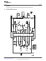
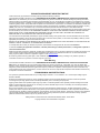
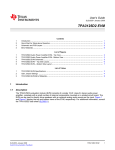
User's Guide
SLOU265 – November 2009
TPA6013A4 Audio Power Amplifier EVM
This user's guide describes the operation of TPA6013A4 evaluation module and presents the schematic,
board layout, and bill of materials of the printed-circuit board.
1
2
3
4
Contents
Introduction ..................................................................................................................
Operation .....................................................................................................................
Reference ....................................................................................................................
TPA6013A4EVM Bill of Materials .........................................................................................
1
2
3
5
List of Figures
1
Top Layer .................................................................................................................... 4
2
Bottom Layer
1
Bill of Materials for TPA6013A4PWPEVM ............................................................................... 5
................................................................................................................
4
List of Tables
1
Introduction
This section provides an overview of the Texas Instruments (TI) TPA6013A4 evaluation module (EVM).
The EVM user guide includes a brief description of the module and a list of EVM specifications.
1.1
Description
The TPA6013A4 is a stereo amplifier with 32-steps DC volume control. TPA6013A4 supports both
speaker and headphone output. TPA6013A4 also has 2-to-1 stereo input MUX.
The TPA6013A4 EVM is a complete, stand-alone audio board. It contains the TPA6013A4 TSSOP (PWP)
stereo amplifier. All components are Pb-free.
1.2
EVM Specifications
Supply voltage range, VDD
4 V to 5.5 V
Supply current, IDD
1.2 A, maximum
Speaker continuous output power, PO, VDD = 5.5 V, 3 Ω, THD+N = 10
%
3W
Headphone continuous output power, PO, VDD = 5 V, 16 Ω, THD+N =
1%
180 mW
SLOU265 – November 2009
Submit Documentation Feedback
TPA6013A4 Audio Power Amplifier EVM
Copyright © 2009, Texas Instruments Incorporated
1
Operation
2
www.ti.com
Operation
This section describes how to operate the TPA6013A4EVM.
2.1
Quick-Start List for Stand-Alone Operation
Use the following steps when operating the TPA6013A4EVM stand-alone board or when connecting the
EVM into an existing circuit.
2.1.1
2.1.2
Power and Ground
1. Ensure that the external power sources are set to OFF.
2. Set the power supply voltage between 4 V and 5.5 V. When connecting the power supply to the EVM,
first connect the ground connection to GND at the POWER terminal block, and then connect the
positive supply to VDD at the POWER terminal block. Verify that the connections are made to the
correct terminals.
Inputs and Outputs
2.1.2.1
Audio Input
1. Connect audio source at the RCA jacks LLINEIN and RLINEIN. Shunt jumper RIN and LIN for
single-ended input.
2. Short position 2 and 3 at 3-pin header RH JP. Audio source right channel will go into RLINEIN of the
amplifier.
3. Short position 2 and 3 at 3-pin header LH JP. Audio source left channel will go into LLINEIN of the
amplifier.
4. TPA6013A4 has 2-to-1 input MUX that can accept 2 single-ended stereo source. To use the MUX:
(a) Connect the first audio source at RCA jacks LLINEIN and RLINEIN. Shunt jumper RIN and LIN for
single-ended input.
(b) Connect the second audio source at test points RHPIN and LHPIN.
(c) Remove shunts at 3-pin headers RH JP and LH JP.
(d) To select LLINEIN and RLINEIN, remove shunt at HP/LINE.
(e) To select LHPIN and RHPIN, shunt at HP/LINE.
2.1.2.2
Audio Output
1. Connect speakers at terminal blocks ROUT and LOUT.
2. TPA6013A4 supports both speaker and headphone output. To select speaker output, remove
headphone in the headphone jack. To select headphone output, insert headphone into the headphone
jack; speaker amplifiers will be turned off automatically.
2.1.2.3
Other Controls
1. Shutdown is controlled by pushbutton S1. Press and hold S1 to place the TPA6013A4 in shutdown
mode. Release S1 to reactivate the TPA6013A4.
2. Volume is controlled by potentiometer.
3. Shunt FADE to enable fade function. Remove shunt to disable fade function.
4. To use SEDIFF and SEMAX function, apply voltage at test points SEDIFF and SEMAX. SEDIFF and
SEMAX can also be controlled by placing resistors of different values at R4 and R7.
2
TPA6013A4 Audio Power Amplifier EVM
Copyright © 2009, Texas Instruments Incorporated
SLOU265 – November 2009
Submit Documentation Feedback
SLOU265 – November 2009
Submit Documentation Feedback
Copyright © 2009, Texas Instruments Incorporated
GND TP3
Black
GND
GND TP2
Black
GND
GRAY
6A/125V
POWER
White
LHPIN
LIN
0.5in
0.5in
0.5in
0.5in
STANDOFFS
GND
RIN
3
3
RH JP
1
1
LH JP
2
GND
2
Do not Place on board
GND GND GND GND
0.5in 0.5in 0.5in 0.5in
Vdd
RCA (Black)
LLINEIN
RCA (Black)
RLINEIN
White
RHPIN
Vdd
C1
1.0ufd/16V
0603
C7
1.0ufd/16V
0603
C6
1.0ufd/16V
0603
C5
C4
1.0ufd/16V
0603
C8
1.0ufd/16V
0603
GND
GND
1.0ufd/16V
0603
C3
1.0ufd/16V
0603
C2
1.0ufd/16V
0603
1.0ufd/16V
0603
10ufd/10V
0805
GND
Vdd
12
11
10
9
8
7
6
5
4
3
2
U1
TSSOP24-PWP
13
14
15
16
17
18
19
20
21
22
23
GND
GND
Black
GND TP1
S1
White
R8
100K
0603
DNP
R7
R6
100K
10K
0603
R14
Vdd
SEDIFF
Vdd
0603
GND
0603
0603
GND
1.0ufd/16V
0603
C9
R5
100K
DNP
R4
100K
R2
0603
100K
R9
0603
Vdd
GND
0603
White
0603
FADE
SEMAX
100.0K
3361P
POT1
GND
Vdd
Vdd
Vdd
Vdd
0603
100K
R3
100K
R1
VOL
White
SDZ
GND
GND
White
HP/LINE
LOUT+
ROUT+
C11
OUT
DNP
1206
R13
GND
1.00K
0603
R10
GRAY
6A/125V
TSSOP24-PWP
GND
PowerPad
DNP
1206
R12
STEREO PHONE JACK,THU,5 PIN
GND
LOUT
220ufd/16V
EIA 7343-31
C10
LHP
White
GND
White
RHP
1.00K
0603
R11
GRAY
6A/125V
220ufd/16V
EIA 7343-31
LOUT-
White
+
+
White
White
3.1
C12
24
ROUT
3
C13
1
ROUT-
www.ti.com
Reference
Reference
This section includes the EVM schematic, board layout reference, and parts list.
TPA6013A4EVM Schematic
TPA6013A4 Audio Power Amplifier EVM
3
Reference
3.2
www.ti.com
TPA6013A4EVM PCB Layers
Figure 1. Top Layer
GND
VDD
+
PCB EDGE
GND
1
WIRE SIDE
WIRE SIDE
2
GND
3
3
+
PCB EDGE
1
TPA6013A4PWPEVM
B
D
WIRE SIDE
2
GND
6509142 Rev A
Figure 2. Bottom Layer
B
D
4
TPA6013A4 Audio Power Amplifier EVM
Copyright © 2009, Texas Instruments Incorporated
SLOU265 – November 2009
Submit Documentation Feedback
TPA6013A4EVM Bill of Materials
www.ti.com
4
TPA6013A4EVM Bill of Materials
Table 1. Bill of Materials for TPA6013A4PWPEVM
Manufacturer/
Part Number
Vendor/
Part Number
RefDes
TPA6013A4PWP
U1
Description
Texas Instruments
TPA6013A4PWP
3-W STEREO AUDIO POWER AMP
W/DC VOLUME TSSOP24-PWP ROHS
MFR
TEXAS INSTRUMENTS
CAPACITORS
EMK107B7105KA-T
C1, C2, C3, C4, C5, C6, C7,
C8, C9, C12
DIGI-KEY
587-1241-1
CAP SMD0603 CERM 1.0μF 16V 10%
X7R ROHS
TAIYO YUDEN
GRM21BR71A106KE51L
C13
DIGI-KEY
490-3905-1
CAP SMD0805 CERM 10μF 10V 10%
X7R ROHS
MURATA
B45197A3227K509
C10, C11
DIGI-KEY
495-1552-1
CAP TANT EIA7343-31 220μF 16V
10% LOW ESR ROHS
EPCOS
ERJ-3GEYJ104V
R1, R2, R3, R5, R6, R8, R9
DIGI-KEY
P100KGCT
RESISTOR SMD0603 100KΩ 5%
THICK FILM 1/10W ROHS
PANASONIC
RC0603FR-071KL
R10, R11
DIGI-KEY
311-1.00KHRCT
RESISTOR SMD0603 THICK FILM
1.00KΩ 1% 1/10W ROHS
YAGEO
ERJ-3GEYJ103V
R14
DIGI-KEY
P10KGCT
RESISTOR SMD0603 10KΩ 5% 1/10W
ROHS
PANASONIC
3361P-1-104GLF
VOL
DIGI-KEY
3361P-104GLFCT
POTENTIOMETER, SMD CERMET
100.0KΩ, 10% SINGLE-TURN, TOP
ADJUST 1/2W ROHS
BOURNS
RESISTORS
JACKS AND HEADERS AND TERMINAL BLOCKS
26630201RP2
LIN, RIN, FADE, HP/LINE
DIGI-KEY
2663S-02
HEADER 2-PIN, PCB 2.0MM ROHS
NORCOMP
PBC03SAAN
LH JP, RH JP
DIGI-KEY
S1011E-03-ND
HEADER THRU MALE 3 PIN 100LS
GOLD ROHS
SULLINS
PJRAN1X1U01X
LLINEIN, RLINEIN
NEWARK
65K7770
JACK, RCA 3-PIN PCB-RA BLACK
ROHS
SWITCHCRAFT
ED555/2DS
LOUT, ROUT, POWER
DIGI-KEY
ED1514
TERMINAL BLOCK 2PIN 6A/125V
ON SHORE TECHNOLOGY
GRAY 3.5mm PITCH 16-28AWG ROHS
35RAPC4BV4
OUT
DIGI-KEY
35RAPC4BV4-ND
STEREO PHONE JACK, THU, 5-PIN,
3.5mm
SWITCHCRAFT
TESTPOINTS AND SWITCHES
5002
LHP, RHP, SDZ, VOL, LHPIN, DIGI-KEY
LOUT+, LOUT-, RHPIN,
5002K
ROUT+, ROUT-, SEMAX,
SEDIFF
PC TESTPOINT, WHITE, ROHS
KEYSTONE ELECTRONICS
5001
GND TP1, GND TP2, GND
TP3
DIGI-KEY
5001K
PC TESTPOINT, BLACK, ROHS
KEYSTONE ELECTRONICS
TL1015AF160QG
S1
DIGI-KEY
EG4344CT
SWITCH, MOM, 160G SMT 4x3MM
ROHS
E-SWITCH
COMPONENTS NOT ASSEMBLED
HW1, HW2, HW3, HW4, R4, R7, R12, R13
SLOU265 – November 2009
Submit Documentation Feedback
TPA6013A4 Audio Power Amplifier EVM
Copyright © 2009, Texas Instruments Incorporated
5
EVALUATION BOARD/KIT IMPORTANT NOTICE
Texas Instruments (TI) provides the enclosed product(s) under the following conditions:
This evaluation board/kit is intended for use for ENGINEERING DEVELOPMENT, DEMONSTRATION, OR EVALUATION PURPOSES
ONLY and is not considered by TI to be a finished end-product fit for general consumer use. Persons handling the product(s) must have
electronics training and observe good engineering practice standards. As such, the goods being provided are not intended to be complete
in terms of required design-, marketing-, and/or manufacturing-related protective considerations, including product safety and environmental
measures typically found in end products that incorporate such semiconductor components or circuit boards. This evaluation board/kit does
not fall within the scope of the European Union directives regarding electromagnetic compatibility, restricted substances (RoHS), recycling
(WEEE), FCC, CE or UL, and therefore may not meet the technical requirements of these directives or other related directives.
Should this evaluation board/kit not meet the specifications indicated in the User’s Guide, the board/kit may be returned within 30 days from
the date of delivery for a full refund. THE FOREGOING WARRANTY IS THE EXCLUSIVE WARRANTY MADE BY SELLER TO BUYER
AND IS IN LIEU OF ALL OTHER WARRANTIES, EXPRESSED, IMPLIED, OR STATUTORY, INCLUDING ANY WARRANTY OF
MERCHANTABILITY OR FITNESS FOR ANY PARTICULAR PURPOSE.
The user assumes all responsibility and liability for proper and safe handling of the goods. Further, the user indemnifies TI from all claims
arising from the handling or use of the goods. Due to the open construction of the product, it is the user’s responsibility to take any and all
appropriate precautions with regard to electrostatic discharge.
EXCEPT TO THE EXTENT OF THE INDEMNITY SET FORTH ABOVE, NEITHER PARTY SHALL BE LIABLE TO THE OTHER FOR ANY
INDIRECT, SPECIAL, INCIDENTAL, OR CONSEQUENTIAL DAMAGES.
TI currently deals with a variety of customers for products, and therefore our arrangement with the user is not exclusive.
TI assumes no liability for applications assistance, customer product design, software performance, or infringement of patents or
services described herein.
Please read the User’s Guide and, specifically, the Warnings and Restrictions notice in the User’s Guide prior to handling the product. This
notice contains important safety information about temperatures and voltages. For additional information on TI’s environmental and/or
safety programs, please contact the TI application engineer or visit www.ti.com/esh.
No license is granted under any patent right or other intellectual property right of TI covering or relating to any machine, process, or
combination in which such TI products or services might be or are used.
FCC Warning
This evaluation board/kit is intended for use for ENGINEERING DEVELOPMENT, DEMONSTRATION, OR EVALUATION PURPOSES
ONLY and is not considered by TI to be a finished end-product fit for general consumer use. It generates, uses, and can radiate radio
frequency energy and has not been tested for compliance with the limits of computing devices pursuant to part 15 of FCC rules, which are
designed to provide reasonable protection against radio frequency interference. Operation of this equipment in other environments may
cause interference with radio communications, in which case the user at his own expense will be required to take whatever measures may
be required to correct this interference.
EVM WARNINGS AND RESTRICTIONS
It is important to operate this EVM within the input voltage range of HPVSS - 0.3 V to HPVDD + 0.3 V and the output voltage range of
HPVSS to HPVDD.
Exceeding the specified input range may cause unexpected operation and/or irreversible damage to the EVM. If there are questions
concerning the input range, please contact a TI field representative prior to connecting the input power.
Applying loads outside of the specified output range may result in unintended operation and/or possible permanent damage to the EVM.
Please consult the EVM User's Guide prior to connecting any load to the EVM output. If there is uncertainty as to the load specification,
please contact a TI field representative.
During normal operation, some circuit components may have case temperatures greater than 85°C. The EVM is designed to operate
properly with certain components above 85°C as long as the input and output ranges are maintained. These components include but are
not limited to linear regulators, switching transistors, pass transistors, and current sense resistors. These types of devices can be identified
using the EVM schematic located in the EVM User's Guide. When placing measurement probes near these devices during operation,
please be aware that these devices may be very warm to the touch.
Mailing Address: Texas Instruments, Post Office Box 655303, Dallas, Texas 75265
Copyright © 2009, Texas Instruments Incorporated
IMPORTANT NOTICE
Texas Instruments Incorporated and its subsidiaries (TI) reserve the right to make corrections, modifications, enhancements, improvements,
and other changes to its products and services at any time and to discontinue any product or service without notice. Customers should
obtain the latest relevant information before placing orders and should verify that such information is current and complete. All products are
sold subject to TI’s terms and conditions of sale supplied at the time of order acknowledgment.
TI warrants performance of its hardware products to the specifications applicable at the time of sale in accordance with TI’s standard
warranty. Testing and other quality control techniques are used to the extent TI deems necessary to support this warranty. Except where
mandated by government requirements, testing of all parameters of each product is not necessarily performed.
TI assumes no liability for applications assistance or customer product design. Customers are responsible for their products and
applications using TI components. To minimize the risks associated with customer products and applications, customers should provide
adequate design and operating safeguards.
TI does not warrant or represent that any license, either express or implied, is granted under any TI patent right, copyright, mask work right,
or other TI intellectual property right relating to any combination, machine, or process in which TI products or services are used. Information
published by TI regarding third-party products or services does not constitute a license from TI to use such products or services or a
warranty or endorsement thereof. Use of such information may require a license from a third party under the patents or other intellectual
property of the third party, or a license from TI under the patents or other intellectual property of TI.
Reproduction of TI information in TI data books or data sheets is permissible only if reproduction is without alteration and is accompanied
by all associated warranties, conditions, limitations, and notices. Reproduction of this information with alteration is an unfair and deceptive
business practice. TI is not responsible or liable for such altered documentation. Information of third parties may be subject to additional
restrictions.
Resale of TI products or services with statements different from or beyond the parameters stated by TI for that product or service voids all
express and any implied warranties for the associated TI product or service and is an unfair and deceptive business practice. TI is not
responsible or liable for any such statements.
TI products are not authorized for use in safety-critical applications (such as life support) where a failure of the TI product would reasonably
be expected to cause severe personal injury or death, unless officers of the parties have executed an agreement specifically governing
such use. Buyers represent that they have all necessary expertise in the safety and regulatory ramifications of their applications, and
acknowledge and agree that they are solely responsible for all legal, regulatory and safety-related requirements concerning their products
and any use of TI products in such safety-critical applications, notwithstanding any applications-related information or support that may be
provided by TI. Further, Buyers must fully indemnify TI and its representatives against any damages arising out of the use of TI products in
such safety-critical applications.
TI products are neither designed nor intended for use in military/aerospace applications or environments unless the TI products are
specifically designated by TI as military-grade or "enhanced plastic." Only products designated by TI as military-grade meet military
specifications. Buyers acknowledge and agree that any such use of TI products which TI has not designated as military-grade is solely at
the Buyer's risk, and that they are solely responsible for compliance with all legal and regulatory requirements in connection with such use.
TI products are neither designed nor intended for use in automotive applications or environments unless the specific TI products are
designated by TI as compliant with ISO/TS 16949 requirements. Buyers acknowledge and agree that, if they use any non-designated
products in automotive applications, TI will not be responsible for any failure to meet such requirements.
Following are URLs where you can obtain information on other Texas Instruments products and application solutions:
Products
Amplifiers
Data Converters
DLP® Products
DSP
Clocks and Timers
Interface
Logic
Power Mgmt
Microcontrollers
RFID
RF/IF and ZigBee® Solutions
amplifier.ti.com
dataconverter.ti.com
www.dlp.com
dsp.ti.com
www.ti.com/clocks
interface.ti.com
logic.ti.com
power.ti.com
microcontroller.ti.com
www.ti-rfid.com
www.ti.com/lprf
Applications
Audio
Automotive
Broadband
Digital Control
Medical
Military
Optical Networking
Security
Telephony
Video & Imaging
Wireless
www.ti.com/audio
www.ti.com/automotive
www.ti.com/broadband
www.ti.com/digitalcontrol
www.ti.com/medical
www.ti.com/military
www.ti.com/opticalnetwork
www.ti.com/security
www.ti.com/telephony
www.ti.com/video
www.ti.com/wireless
Mailing Address: Texas Instruments, Post Office Box 655303, Dallas, Texas 75265
Copyright © 2009, Texas Instruments Incorporated