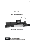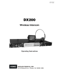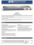
1
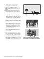
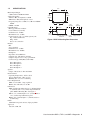
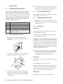
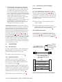
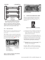
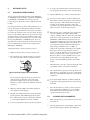
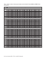
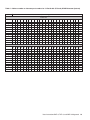
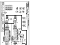
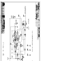
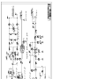
USER INSTRUCTIONS BKP-4, TKP-4, AND WKP-4 KEYPANELS ADAM™, ADAM™ CS, AND ZEUS™ INTERCOM SYSTEMS Mic t se ad He g in ait ll W Ca py Co t se ad He ar Cle e lum Vo ten Lis lk Ta WKP-4 (Mounting box optional) ™ 9350-7646-000 Rev E, 8/00 PROPRIETARY NOTICE CUSTOMER SUPPORT The RTS product information and design disclosed herein were originated by and are the property of Telex Communications, Inc. Telex reserves all patent, proprietary design, manufacturing, reproduction, use and sales rights thereto, and to any article disclosed therein, except to the extent rights are expressly granted to others. Technical questions should be directed to: COPYRIGHT NOTICE Copyright 1999 by Telex Communications, Inc. All rights reserved. Reproduction in whole or in part without prior written permission from Telex is prohibited. Customer Service Department RTS/Telex, 12000 Portland Avenue South Burnsville, MN 55337 U.S.A. Telephone: (952) 884-4051 Fax: (800) 323-0498 RETURN SHIPPING INSTRUCTIONS PROCEDURE FOR RETURNS UNPACKING AND INSPECTION Immediately upon receipt of the equipment, inspect the shipping container and the contents carefully for any discrepancies or damage. Should there be any, notify the freight company and the dealer at once. WARRANTY INFORMATION RTS products are warranted by Telex Communications, Inc. to be free from defects in materials and workmanship for a period of three years from the date of sale. The sole obligation of Telex during the warranty period is to provide, without charge, parts and labor necessary to remedy covered defects appearing in products returned prepaid to Telex. This warranty does not cover any defect, malfunction or failure caused beyond the control of Telex, including unreasonable or negligent operation, abuse, accident, failure to follow instructions in the Service Manual or the User Manual, defective or improper associated equipment, attempts at modification and repair not authorized by Telex, and shipping damage. Products with their serial numbers removed or effaced are not covered by this warranty. To obtain warranty service, follow the procedures entitled "Procedure For Returns" and "Shipping to Manufacturer for Repair or Adjustment". This warranty is the sole and exclusive express warranty given with respect to RTS products. It is the responsibility of the user to determine before purchase that this product is suitable for the user's intended purpose. ANY AND ALL IMPLIED WARRANTIES, INCLUDING THE IMPLIED WARRANTY OF MERCHANTABILITY ARE LIMITED TO THE DURATION OF THIS EXPRESS LIMITED WARRANTY. NEITHER TELEX NOR THE DEALER WHO SELLS RTS PRODUCTS IS LIABLE FOR INCIDENTAL OR CONSEQUENTIAL DAMAGES OF ANY KIND. 2 User Instructions BKP-4, TKP-4, and WKP-4 Keypanels If a repair is necessary, contact the dealer where this unit was purchased. If repair through the dealer is not possible, obtain a RETURN AUTHORIZATION from: Customer Service Department Telex Communications, Inc. Telephone: (877) 863-4169 Fax: (800) 323-0498 DO NOT RETURN ANY EQUIPMENT DIRECTLY TO THE FACTORY WITHOUT FIRST OBTAINING A RETURN AUTHORIZATION. Be prepared to provide the company name, address, phone number, a person to contact regarding the repair, the type and quantity of equipment, a description of the problem and the serial number(s). SHIPPING TO MANUFACTURER FOR REPAIR OR ADJUSTMENT All shipments of RTS products should be made via United Parcel Service or the best available shipper, prepaid. The equipment should be shipped in the original packing carton; if that is not available, use any suitable container that is rigid and of adequate size. If a substitute container is used, the equipment should be wrapped in paper and surrounded with at least four inches of excelsior or similar shock-absorbing material. All shipments must be sent to the following address and must include the Return Authorization. Factory Service Department Telex Communications, Incorporated West 1st Street Blue Earth, MN 56013 U.S.A. Upon completion of any repair the equipment will be returned via United Parcel Service or specified shipper collect. End-User License Agreement for Telex® Software IMPORTANT - Please read this document carefully before using this product. THIS DOCUMENT STATES THE TERMS AND CONDITIONS UPON WHICH TELEX COMMUNICATIONS, INC. (the “COMPANY”) OFFERS TO LICENSE THE INSTALLED SOFTWARE OR PROGRAM (“the SOFTWARE”) FOR USE WITH THE PRODUCT IN WHICH IT WAS INSTALLED. YOU ARE AGREEING TO BECOME BOUND BY THE TERMS OF THIS AGREEMENT. IF YOU DO NOT AGREE TO THE TERMS OF THIS AGREEMENT, DO NOT USE THIS PRODUCT. PROMPTLY RETURN THE PRODUCT TO THE PLACE WHERE YOU OBTAINED IT FOR A FULL REFUND. The installed software as supplied by the Company is licensed, not sold, to you for use only under the terms of this license, and the Company reserves all rights not expressly granted to you. You own the product or other media on or in which the Software is originally or subsequently recorded or fixed, but the Company retains ownership of all copies of the Software itself. 1. License: This license allows you to use the Software for internal purposes only on a single product in which it was installed. 2. Restrictions: (a) You may not market, distribute or transfer copies of the Software to others or electronically transfer or duplicate the Software. YOU MAY NOT REVERSE ENGINEER, DECOMPILE, DISASSEMBLE, MODIFY, ADAPT, TRANSLATE, RENT, LEASE OR LOAN THE SOFTWARE OR CREATE DERIVATIVE WORKS BASED ON THE SOFTWARE OR ANY ACCOMPANYING WRITTEN MATERIALS. (b) The Software and the accompanying written materials are copyrighted. Unauthorized copying of the Software, including portions thereof or the written materials, is expressly forbidden. (c) You understand that the Company may update or revise the Software and in so doing incurs no obligation to furnish such updates to you. 3. Limited Warranty: The Company does not warrant that the operation of the Software will meet your requirements or operate free from error. The Company DISCLAIMS ALL OTHER WARRANTIES AND CONDITIONS EITHER EXPRESS OR IMPLIED, INCLUDING THE WARRANTIES OF MERCHANTABILITY, FITNESS FOR A PARTICULAR PURPOSE AND NON-INFRINGEMENT OF THIRD PARTY RIGHTS. 4. Limited Liability: The liability of the Company for any claims arising out of this License based upon the Software, regardless of the form of action, shall not exceed the greater of the license fee for the Software or $50. 38109-709 Rev A 10/97 User Instructions BKP-4, TKP-4, and WKP-4 Keypanels 3 This page intentionally left blank. 4 User Instructions BKP-4, TKP-4, and WKP-4 Keypanels TABLE OF CONTENTS DESCRIPTION AND SPECIFICATIONS · · · · · · · · · · · · · · · · · · · · · · · · · · · · · · · · · · · · · · · · · · · · · · · · · · · 7 GENERAL DESCRIPTION . . . . . . . . . . . . . . . . . . . . . . . . . . . . . . . . . . . . . . . . . . . . . . . . . . . . . . . . 7 FEATURES. . . . . . . . . . . . . . . . . . . . . . . . . . . . . . . . . . . . . . . . . . . . . . . . . . . . . . . . . . . . . . . . . 7 FRONT PANEL DESCRIPTION . . . . . . . . . . . . . . . . . . . . . . . . . . . . . . . . . . . . . . . . . . . . . . . . . . . . . 7 BACK PANEL / CIRCUIT BOARD SWITCHES AND CONNECTORS . . . . . . . . . . . . . . . . . . . . . . . . . . . . . . . . 8 SPECIFICATIONS . . . . . . . . . . . . . . . . . . . . . . . . . . . . . . . . . . . . . . . . . . . . . . . . . . . . . . . . . . . . . 9 INSTALLATION · · · · · · · · · · · · · · · · · · · · · · · · · · · · · · · · · · · · · · · · · · · · · · · · · · · · · · · · · · · · · · · 10 UNPACKING AND INSPECTION. . . . . . . . . . . . . . . . . . . . . . . . . . . . . . . . . . . . . . . . . . . . . . . . . . . . 10 WKP-4 BOX INSTALLATION . . . . . . . . . . . . . . . . . . . . . . . . . . . . . . . . . . . . . . . . . . . . . . . . . . . . . 10 TKP-4 BOX INSTALLATION . . . . . . . . . . . . . . . . . . . . . . . . . . . . . . . . . . . . . . . . . . . . . . . . . . . . . . 10 CONFIGURATION SWITCHES . . . . . . . . . . . . . . . . . . . . . . . . . . . . . . . . . . . . . . . . . . . . . . . . . . . . . 10 DIP Switches . . . . . . . . . . . . . . . . . . . . . . . . . . . . . . . . . . . . . . . . . . . . . . . . . . . . . . . . . . . . . 10 Address Switch . . . . . . . . . . . . . . . . . . . . . . . . . . . . . . . . . . . . . . . . . . . . . . . . . . . . . . . . . . . . 11 CONNECTIONS . . . . . . . . . . . . . . . . . . . . . . . . . . . . . . . . . . . . . . . . . . . . . . . . . . . . . . . . . . . . . 12 Mic Connector. . . . . . . . . . . . . . . . . . . . . . . . . . . . . . . . . . . . . . . . . . . . . . . . . . . . . . . . . . . . . 12 Headset Connector . . . . . . . . . . . . . . . . . . . . . . . . . . . . . . . . . . . . . . . . . . . . . . . . . . . . . . . . . . 12 Connection To Intercom System . . . . . . . . . . . . . . . . . . . . . . . . . . . . . . . . . . . . . . . . . . . . . . . . . . . 12 Power Connection . . . . . . . . . . . . . . . . . . . . . . . . . . . . . . . . . . . . . . . . . . . . . . . . . . . . . . . . . . . 13 STARTUP AND OPERATIONAL CHECK . . . . . . . . . . . . . . . . . . . . . . . . . . . . . . . . . . . . . . . . . . . . . . . 13 KEYPANEL SETUP· · · · · · · · · · · · · · · · · · · · · · · · · · · · · · · · · · · · · · · · · · · · · · · · · · · · · · · · · · · · · · 14 ASSIGNING INTERCOM KEYS . . . . . . . . . . . . . . . . . . . . . . . . . . . . . . . . . . . . . . . . . . . . . . . . . . . . 14 CLEARING KEY ASSIGNMENTS . . . . . . . . . . . . . . . . . . . . . . . . . . . . . . . . . . . . . . . . . . . . . . . . . . . 14 PRINTING DESIGNATION STRIPS . . . . . . . . . . . . . . . . . . . . . . . . . . . . . . . . . . . . . . . . . . . . . . . . . . 15 CHANGING SETUP PAGES. . . . . . . . . . . . . . . . . . . . . . . . . . . . . . . . . . . . . . . . . . . . . . . . . . . . . . . 15 OPERATION · · · · · · · · · · · · · · · · · · · · · · · · · · · · · · · · · · · · · · · · · · · · · · · · · · · · · · · · · · · · · · · · · 15 HEADSET BUTTON OPERATION . . . . . . . . . . . . . . . . . . . . . . . . . . . . . . . . . . . . . . . . . . . . . . . . . . . 15 DIP switch 4 in Open position (default) . . . . . . . . . . . . . . . . . . . . . . . . . . . . . . . . . . . . . . . . . . . . . . . 15 DIP switch 4 in Closed position. . . . . . . . . . . . . . . . . . . . . . . . . . . . . . . . . . . . . . . . . . . . . . . . . . . . 15 INTERCOM KEY OPERATION . . . . . . . . . . . . . . . . . . . . . . . . . . . . . . . . . . . . . . . . . . . . . . . . . . . . . 15 Momentary vs Latching Operation . . . . . . . . . . . . . . . . . . . . . . . . . . . . . . . . . . . . . . . . . . . . . . . . . . 15 Intercom Key Operation for Different Types of Key Assignments. . . . . . . . . . . . . . . . . . . . . . . . . . . . . . . . . . 16 Intercom Key Indications . . . . . . . . . . . . . . . . . . . . . . . . . . . . . . . . . . . . . . . . . . . . . . . . . . . . . . . 16 CALL WAITING OPERATION FOR INCOMING CALLS. . . . . . . . . . . . . . . . . . . . . . . . . . . . . . . . . . . . . . . 16 OPERATION WITH THE TIF-951 TELEPHONE INTERFACE . . . . . . . . . . . . . . . . . . . . . . . . . . . . . . . . . . . . 17 DISPLAYING KEY ASSIGNMENTS . . . . . . . . . . . . . . . . . . . . . . . . . . . . . . . . . . . . . . . . . . . . . . . . . . 17 DISPLAYING THE PORT NUMBER . . . . . . . . . . . . . . . . . . . . . . . . . . . . . . . . . . . . . . . . . . . . . . . . . . 17 User Instructions BKP-4, TKP-4, and WKP-4 Keypanels 5 LIST OF FIGURES Figure 1. Front Panel View. · · · · · · · · · · · · · · · · · · · · · · · · · · · · · · · · · · · · · · · · · · · · · · · · · · · · · · · · · · 7 Figure 2. BKP-4 Back Panel View. · · · · · · · · · · · · · · · · · · · · · · · · · · · · · · · · · · · · · · · · · · · · · · · · · · · · · · · 8 Figure 3. WKP-4/TKP-4 Configuration Switches and Connectors on Circuit Board (WKP-4 Shown) · · · · · · · · · · · · · · · · · · · · · 8 Figure 4. WKP-4 Mounting Box Dimensions · · · · · · · · · · · · · · · · · · · · · · · · · · · · · · · · · · · · · · · · · · · · · · · · · 9 Figure 5. RJ12 Intercom cable wiring diagram · · · · · · · · · · · · · · · · · · · · · · · · · · · · · · · · · · · · · · · · · · · · · · · · 12 Figure 6. 9-pin Intercom cable wiring diagram. · · · · · · · · · · · · · · · · · · · · · · · · · · · · · · · · · · · · · · · · · · · · · · · 13 Figure 7. Intercom and Power Terminal Block Pinouts for the TKP-4 / WKP-4. · · · · · · · · · · · · · · · · · · · · · · · · · · · · · · · 13 Figure 8. Use tie wraps to secure the cables (WKP-4 installation). · · · · · · · · · · · · · · · · · · · · · · · · · · · · · · · · · · · · · · 13 Figure 9. Call Waiting Window and Key · · · · · · · · · · · · · · · · · · · · · · · · · · · · · · · · · · · · · · · · · · · · · · · · · · · 13 Figure 10. Scroll, Copy and Clear Buttons · · · · · · · · · · · · · · · · · · · · · · · · · · · · · · · · · · · · · · · · · · · · · · · · · · 14 LIST OF TABLES Table 1. Address number vs intercom port numbers for 8-Port Audio I/O Cards (ADAM and ADAM CS Intercom Systems) · · · · · · 18 Table 2. Address number vs intercom port numbers for 12-Port Audio I/O Cards (ADAM Intercom Systems) · · · · · · · · · · · · · · 19 6 User Instructions BKP-4, TKP-4, and WKP-4 Keypanels 1 DESCRIPTION AND SPECIFICATIONS 1.1 GENERAL DESCRIPTION The BKP-4. TKP-4, and WKP-4 are ideal for users who want full access to the most commonly used keypanel features, and who generally communicate with four or less locations in the intercom system at any given time. The BKP-4 is suitable for desktop use and is powered from an AC mains outlet. The TKP-4 is designed to fit in a Tektronics equipment bay. The WKP-4 is designed for wall mounting. The TKP-4 and WKP-4 may be ordered with a universal AC power supply, or the installer can supply power from another source. 1.2 FEATURES ■ Works with ADAM, ADAM CS and Zeus Digital Matrix Intercom Systems. ■ Full-function intercom keys with LED indicators. Alphanumeric call waiting display with response key. (Call waiting display is optional on the WKP-4.) ■ ■ Access to intercom key and setup page assignments. (Optional on WKP-4.) ■ 4-wire, balanced audio input and output. Several microphone/speaker/headphone combinations possible, including: Headset (microphone + headphones), headphones + panel mounted microphone, speaker + panel mounted microphone, speaker + handheld microphone. Works with: RTS headsets with A4M connector, and MCP5 and MCP6 Panel Microphones. ■ ■ ■ 1.3 1) 2) 3) 4) 5) 6) 7) 8) 9) Latching can be disabled via an options switch (13) or from ADAMedit or ZEUSedit. Key Indicators: Two bi-color (red and green) LED indicators for each key. Provide indications for talk on/off, listen on/off, incoming call, busy (for keys assigned to talk to IFB's), and in-use (for keys assigned to talk to either IFB's or ISO's). Designation Strip Holder: Holds printed strip identifying key assignments. Works with ADAMedit and ZEUSedit designation strip print feature. Call Waiting Display (Optional on WKP-4) and Response Key: 4-character, alphanumeric display for incoming caller names. Talkback to caller via the response key. The call waiting window and response key are also used with the copy, clear, and scroll keys (5). Copy, Clear, and Scroll keys (Optional on the WKP-4): Used for key and setup page assignment. Can also be used to talk to any location in the intercom system when no intercom key is assigned. (Note: There are 4 setup pages. Each contains a complete set of key assignments.) Headset On/Off Key with Indicator. When the headset is on, the speaker output and panel mic are off. Listen Volume Control for Headset or Speaker. Panel Mic Connector: 1/4", 3-conductor phone jack. Accepts MCP5 or MCP6 Panel Microphone. Monaural Headset Connector: A4F (XLR-4F) connector. Accepts any RTS headset with A4M (XLR4M) connector. Also accepts monaural headphones for use with a panel microphone, or accepts a handheld microphone for use with the speaker. Easy installation setup. Ready for worldwide use. The BKP-4 accepts any mains voltage from 90-240 VAC, 47/63 Hz. The TKP-4 and WKP-4 can be powered from an optional AC adapter which accepts 100-240 VAC, 47/63. Alternatively, the TKP-4 and WKP-4 may be powered from a user-supplied, 15-24 VDC, 1 amp, regulated power source.) FRONT PANEL DESCRIPTION Intercom Keys: Assignable for several types of operation, including talk only, listen only, talk with auto-listen, and all-call (where activating the key also activates all keys to the left of that key). Keys feature momentary or latching operation. For momentary operation, the operator presses and holds a key while communicating, then releases it when finished. For latching operation, the operator taps a key to turn it on, then taps it again to turn it off. Figure 1. Front Panel View. (Numbered items refer to front panel description.) User Instructions BKP-4, TKP-4, and WKP-4 Keypanels 7 BACK PANEL / CIRCUIT BOARD SWITCHES AND CONNECTORS Incoming Call Timeout Select: Incoming call LED flash can be set for 15 seconds, or until the caller's key is released. ■ Speaker / Microphone Selection: A DIP switch, together with the front panel Headset switch, permits any of the following speaker / microphone combinations: internal speaker with panel microphone; headphones with panel microphone; speaker with 4-pin dynamic microphone; headset with boom-mounted dynamic mic. ■ 12345678 Frame 10 11 12 78 9A 34 56 Open Close Options CDE ■ 90-240 VAC B 10) BKP-4: Universal Power Input: Accepts any mains voltage from 90-240 VAC, 47-63 Hz. TKP-4 and WKP-4: Terminals for DC power connection. 11) Intercom Frame Connectors. All units have both 9-pin female Dsub (DE9S) and RJ12 connectors. The TKP-4 and WKP-4 also include spring-clamp terminals. 12) Options DIP Switches: ■ Name Display for Assigned Keys: Assigned intercom keys provide an LED flash for incoming call announce. Optionally, the caller's name can also be displayed in the call waiting window. (Incoming calls from unassigned callers are always displayed in the call waiting window.) 1 F0 2 1.4 Address 13 Figure 2. BKP-4 Back Panel View. 11 10 10 Latching: The electronic latching feature for the intercom keys can be turned on or off as previously mentioned. 13) Address Select Switch: 16-position rotary switch: Selects the keypanel's location in an intercom group. The combination of intercom group number and Address switch setting determines a keypanel's unique address within the intercom system. Note: Only positions 1-8 are used for Zeus and ADAM CS intercom systems, or ADAM intercom systems with 8-port Audio I/O cards. Only positions 1-C are used for ADAM intercom systems with 12-port Audio I/O cards. The remaining switch positions are not used. 8 User Instructions BKP-4, TKP-4, and WKP-4 Keypanels 11 10 12 10 13 10 Figure 3. WKP-4/TKP-4 Configuration Switches and Connectors on Circuit Board (WKP-4 Shown) 1.5 SPECIFICATIONS Matrix Input/ Output 8 dBu nominal, 20 dBu maximum Audio Performance SNR at 8 dBu (A-weighted): > 70 dB THD+N at 8 dBu (Unweighted): < 0.5% Frequency Response at 8 dBu: ± 1.5 dB from 100 Hz 20 kHz CMRR: > 70 dB Panel Mic Input Mic Type: Electret condenser Power: Phantom (+5V DC) Nominal Level: -42 dBu Maximum Level: -25 dBu Connector Type: 1/4", 3-conductor phone jack. Tip: +Audio and DC bias Ring: -Audio Sleeve: No connection Headset Mic Type: Dynamic Nominal Level: -55 dBu Maximum Level: -40 dBu Headphone Impedance: 50 to 600 ohms Output Power: 150 mW into 50 ohms Output Voltage Level: 8 volts p-p maximum Connector Type: D4F (Mates with A4M) 8.11" 206 mm 6.102" 155 mm 3.937" 100 mm 6.102" 155 mm 2.7" 69 mm 1.575" 40 mm .812" Dia (3 Places) 20.63 mm 1.56" 39.6 mm 3.15“ 80 mm 1.56" 39.6 mm Opposite side Figure 4. WKP-4 Mounting Box Dimensions Pin 1: Microphone Pin 2: Microphone + Pin 3: Headphone Pin 4: Headphone + Speaker Output: 4 Watts into 8 ohms maximum Environmental Operating Temperature: -20°C to 50°C Storage Temperature: -40°C to 85°C Humidity: 0 to 95%, non-condensing Power Requirements WKP-4: 15-24 VDC, 1 amp, regulated BKP-4: 90 to 240 VAC, 47 / 63 Hz Dimensions WKP-4 (without mounting box): 6.5" (165mm) high x 9" (229mm) wide x 2.8" (71mm) deep behind front panel. WKP-4 Mounting Box: See Figure 4. TKP-4: 5.2" (132mm) high x 8.38" (213mm) wide x 3.25" (83mm) deep behind front panel. BKP-4: 4.6" (117mm) high x 9" (229mm) wide x 7" (178mm) deep Finish Aluminum front panel and case, light gray finish Approvals UL, CSA, VDE, CE User Instructions BKP-4, TKP-4, and WKP-4 Keypanels 9 ☞ If you are not using conduit to route the cables, use a 2 INSTALLATION 2.1 UNPACKING AND INSPECTION As soon as possible after receipt, inspect the container and contents for physical damage that may have occurred in shipping. If damage has occurred, immediately (within 24 hours of receipt of equipment) contact the carrier involved and file a claim. Save all packing materials, and request an immediate inspection by the carrier’s insurance claims agent. The container includes one or more of the following items, depending on the order: plastic bushing or similar device at the cable entrance into the box to prevent abrasion of the wires. 2.3 TKP-4 BOX INSTALLATION Insert the TKP-4 into a Tektronics equipment bay so that the spring clips are fully seated. 2.4 CONFIGURATION SWITCHES ☞ Important! If you change any configuration switch settings during operation, you must momentarily turn off power to reset. Quantity Description 1 BKP-4, TKP-4, or WKP-4 Keypanel 1 Power Cord (BKP-4 only) 1 User Manual 1 WKP-4 Mounting Box (Optional) DIP Switch 1 1 AC Power Adapter. Input: 100-240 VAC, 47-63 Hz, .4A. Output: 15 VDC, 1A max (Optional, used only for WKP-4 and TKP-4) Open: Default setting. All incoming calls appear in the call waiting display (if present). 2.2 1. 2.4.1 WKP-4 BOX INSTALLATION If the WKP-4 was supplied assembled to the mounting box, remove the four (4) screws from the front panel. DIP Switches Closed: Only calls for unassigned callers appear in the call waiting display (if present). Description: Any intercom key that is already assigned to talk/listen to a specific intercom port will always provide an LED flash for incoming calls from that port. If a designation strip is used (see Printing Designation Strips, page 15 ) the keypanel operator can identify the caller from the designation strip. Optionally, the caller's name can also display in the call waiting window. If you don't want this to happen, set DIP switch 1 to Close. ☞ The above description applies only to assigned keys. 2. Mount the box in a suitable size wall opening using appropriate mounting screws (not supplied). Whenever there is an incoming call, and there is no key assigned to the caller, that caller's name will always display in the call waiting window. DIP Switch 2 Open: Default setting. 15 second flash after incoming call is received. Closed: LED flash until caller releases key. ALTERNATE CABLE ENTRANCES 3. Route the intercom and power wires into the box. Reinstall the front panel after all dip switch settings and connections are completed as described on the following pages. 10 User Instructions BKP-4, TKP-4, and WKP-4 Keypanels Description: Whenever there is an incoming call and there is a talk key assigned to the caller, the talk LED next to that key will flash. The flash can be set for 15 second timeout, or until the caller's talk key is released. DIP Switch 3 Open: Default setting. TIF-951 operation enabled. Closed: keypanel cannot answer incoming calls to TIF-951. Description: The keypanel can answer incoming telephone calls received by an RTS Model TIF-951 Telephone Interface. However, it cannot perform any other telephone operations. For example, it cannot force the TIF-951 to hang up at the end of a call. In many cases, the TIF-951 can detect a hang up at the far end of the line and then hang up itself. However, this may not always be the case in all phone systems. In such cases you may wish to completely disable keypanel operation with the TIF-951. 2.4.2 ☞ In Zeus, ADAM CS, and ADAM intercom systems, intercom ports are arranged in groups of 8 or 12 intercom ports. Within each group, each keypanel keypanel is uniquely identified by its Address switch setting. The Address switch has a white pointer which points to the current switch setting. Determine the proper setting as follows: DIP Switch 5 Open: Default setting. Latching turned on. Closed: Latching turned off. Description: An intercom key can always be turned on for momentary conversation by pressing and holding the key during the conversation. There is also an electronic latching feature that lets you tap intercom keys to turn them on or off. This permits convenient hands-free conversation. However it can also result in a talk circuit being left on unintentionally. For example, a key that talks to a public address system could be accidentally left on. Or an IFB key (a type of key assignment that is often used by a director or producer to give instructions to a listener, such as a news anchor during a television broadcast) could accidentally be left on, causing confusion for the IFB listener. To prevent such accidents, the latching feature can be turned off. DIP Switches 6-8 Not used. Leave Open. 56 34 1 F0 2 Description: Typically, you will use the keypanel either with a panel microphone and a speaker or with a headset. The special applications setting is seldom used. CDE Closed: Special Applications. Use a dynamic mic (connected to the Headset connector) with the speaker. Or, use headphones (connected to the Headset connector) with a panel mic (connected to the Mic connector). 9A B 78 DIP Switch 4 Open: Default setting. Use a panel mic (connected to the Mic connector) to talk and use the speaker to listen. Or, use a headset (connected to Headset connector) to talk and listen. Address Switch Important! Always reset the keypanel after changing the Address switch setting. Do this by briefly removing power to the keypanel. Zeus Intercom Systems: Intercom port connectors on the Zeus back panel are arranged in three groups of eight intercom ports. For each group, intercom port connectors are labeled ID 1, ID 2, etc. When you connect a keypanel keypanel to Zeus, set the keypanel Address switch to match the corresponding ID number on the Zeus back panel. Note that address switch settings 0, and 9 through F are not used. ADAM CS Intercom Systems: Each Audio I/O card contains 1 group of 8 intercom ports. However, the method of breaking out the groups depends on the type of connectors on the back panel. To determine the keypanel Address switch setting, use the planning worksheets in the ADAM CS Installation Manual. These are located near the back of the Installation Manual: • ADAM CS with RJ12 or DB-9 back panel: You can determine the keypanel address from the worksheets in either of two ways: 1) If you know the port number that a keypanel will be connected to, look up the port number in the worksheet, then read across to the appropriate logical keypanel number for that port number. Use that number to set the keypanel Address switch. 2) If you know the connector number (on the back of the ADAM CS frame) that the keypanel will be connected to, look up that connector number in the worksheet, then read across to the appropriate logical keypanel number. Use that number to set the keypanel Address switch. Note that address switch settings 0, and 9 through F are not used. User Instructions BKP-4, TKP-4, and WKP-4 Keypanels 11 • ADAM CS frame with 50-pin Telco back panel: You can determine the keypanel address from the worksheet in either of two ways: 1) If you know the port number that a keypanel will be connected to, look up the port number in the worksheet, then read across to the appropriate logical keypanel number for that port number. Use that number to set the keypanel Address switch. 2) If you know the connector numbers and pin numbers that the keypanel will be connected to, look up these numbers in the worksheet, then read across to the appropriate logical keypanel number. Use that number to set the keypanel Address switch. Note that address switch settings 0, and 9 through F are not used. ADAM Intercom Systems: Each Audio I/O contains 1 group of either 8 or 12 intercom ports per card. However, the individual intercom ports may be broken out using various types of breakout panels or punch blocks, and groups may not be easily identified. It may be easier to set the keypanel Address switch using the actual intercom port numbers. To do this, refer to Table 1, page 18 (for 8-port cards) or Table 2, page 19 (for 12-port cards). Locate the intercom port number to which the keypanel will be connected. Then, read across to the “Address” column to find the Address number. Set the keypanel Address switch to this number. Note: settings 0, and 9 through F are not used with 8-port cards settings 0, and C through F are not used with 12-port cards. 2.5 CONNECTIONS 2.5.1 Mic Connector 2.5.3 Connection To Intercom System BKP-4 Connection Use a standard RTS intercom cable. Either a 9-pin or RJ12 type can be used. Refer to Figure 5 or 6. Plug one end of the cable into the appropriate Frame connector on the back panel of the keypanel. Plug the other end into the appropriate port of the intercom system. (This will be the port number that you designated previously when setting the Address switch.) ☞ Keypanels may be connected while the intercom system is running. ☞ Note that 9-pin intercom cables for use with an ADAM CS frame must use special connectors at the intercom matrix end as described in Figure 6. TKP-4 / WKP-4 Connection You can use either type of standard intercom cable as shown in Figure 5 or 6. Alternatively, you can connect directly to the terminal block as shown in Figure 7. In either case, use tie wraps to secure the wires as shown in Figure 8. CONTACTS RJ12 MODULAR PLUG AMP 5-555042-3 or equivalent (View from cable entrance) 123456 To connect a panel microphone, such as the RTS model MCP5 or MCP6, screw the microphone into the Mic connector on the front panel of the keypanel. ☞ For Mic connector specifications, see page 9. 2.5.2 3 TWISTED PAIR TELEPHONE CABLE PAIR 1: AUDIO TO MATRIX PAIR 2: AUDIO FROM MATRIX PAIR 3: DATA Headset Connector The Headset connector accepts a monaural, dynamic-microphone headset (headphones and microphone). If you use a headset, make sure DIP switch 4 is set to the Open position (page 11). 1 2 3 Alternatively, headphones can be connected when a panel microphone is used for talkback. Or, a handheld dynamic microphone can be connected when a speaker is used for listening. If you use either of these special configurations, make sure DIP switch 4 is set to the Close position (page 11). ☞ For Headset connector specifications, see page 9. 12 User Instructions BKP-4, TKP-4, and WKP-4 Keypanels Use AMP Chordal Crimp Tool 231648-1 or equivalent LATCH 4 5 6 DATA AUDIO FROM MATRIX + AUDIO TO MATRIX + AUDIO TO MATRIX AUDIO FROM MATRIX DATA + 1 2 3 4 5 6 Figure 5. RJ12 Intercom cable wiring diagram DE-9P (MALE) TO KEYPANEL 1 DE-9S (FEMALE) TO INTERCOM SYSTEM* + - 1 + - 4 AUDIO TO MATRIX + 7 AUDIO FROM MATRIX DATA 2 6 4 5 9 7 8 3 2 6 5 9 8 3 CABLE TYPE: BELDEN 8777 * IMPORTANT! When connecting to an ADAM CS back panel, use only low-profile cable connectors such as AMP Part No. 747516-3 (Telex Part No. 59926-678) Figure 6. 9-pin Intercom cable wiring diagram. Important: Shield connections at keypanel end are optional and may cause ground loops if used. Figure 8. Use tie wraps to secure the cables (WKP-4 installation). 2.6 STARTUP AND OPERATIONAL CHECK When power is applied, all LEDs will first flash red, then green. This confirms that all LEDs are workin