1
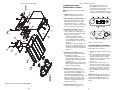
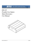
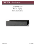
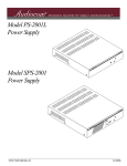
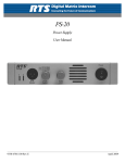
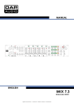
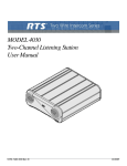
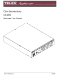
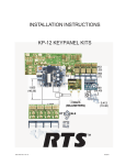
User Manual
BP-319 / BP-351
User Station
9350-7753-000 Rev G
08/2007
BP-319 / BP-351 User Station
BP-319 / BP-351 User Station
THIS PAGE LEFT INTENTIONALLY BLANK
BP-319 / BP-351 User Station
BP-319 / BP-351 User Station
PROPRIETARY NOTICE
RETURN SHIPPING INSTRUCTIONS
The product information and design
disclosed herein were originated by and
are the property of Telex Communications,
Inc. Telex reserves all patent, proprietary
design, manufacturing, reproduction, use
and sales rights thereto, and to any article
disclosed therein, except to the extent
rights are expressly granted to others.
Customer Service Department
Telex Communications, Inc. (Lincoln, NE)
Telephone: 402-467-5321
Fax: 402-467-3279
Factory Service: 800-553-5992
Please include a note in the box which
supplies the company name, address,
phone number, a person to contact
regarding the repair, the type and quantity
of equipment, a description of the problem
and the serial number(s).
COPYRIGHT NOTICE
Copyright 2006 by Telex Communications,
Inc. All rights reserved. Reproduction, in
whole or in part, without prior written
permission from Telex is prohibited.
SHIPPING TO THE MANUFACTURER
All shipments of product should be made
via UPS Ground, prepaid (you may
request from Factory Service a different
shipment method). Any shipment
upgrades will be paid by the customer.
The equipment should be shipped in the
original packing carton. If the original
carton is not available, use any suitable
container that is rigid and of adequate
size. If a substitute container is used, the
equipment should be wrapped in paper
and surrounded with at least four (4)
inches of excelsior or similar shockabsorbing material. All shipments must be
sent to the following address and must
include the Proof of Purchase for warranty
repair. Upon completion of any repair the
equipment will be returned via United
Parcel Service or specified shipper,
collect.
Factory Service Department
Telex Communications, Inc.
8601 East Cornhusker Hwy.
Lincoln, NE 68507 U.S.A.
Attn: Service
WARRANTY NOTICE
See the enclosed warranty card for further
details.
CUSTOMER SUPPORT
Technical questions should be directed to:
Customer Service Department
RTS/Telex Communications, Inc.
12000 Portland Avenue South
Burnsville, MN 55337 USA
Telephone: 800-392-3497
Fax: 800-323-0498
Figure 7 - Connector Plate Assembly, BP351 - 90207486000
14
3
BP-319 / BP-351 User Station
BP-319 / BP-351 User Station
6
Description
7
17
2
The BP-319/351 are beltpacks for use with RTS 2-wire intercom systems. The BP-319 is a
microprocessor controlled one-channel intercom, where the BP-351 is a microprocessor
controlled two-channel select intercom beltpack. Both have connections for headset/earset
microphones (Dynamic/Electret).
25
Features
Features of the BP-319/351 include:
Microprocessor controlled Microphone Kill Detect.
J2
•
•
•
5
Call function that allows the user to send or receive call signals to other devices on
the intercom channel, including Audible Call Alert on the listen side.
4
•
Powered externally, via the intercom system power supply on channel one.
Headset/earset 4 or 5-pin XLR connection set for intercom operation.
J1
12
18
(2PLS)
Connections and Controls
3
BP-319/351 has the following connections and controls:
19
•
A loop-through connection connects several beltpacks in a chain. Since this is often
the preferred method of connection, a line loop connector has been added to new
units. See Figure 1).
Headset connectors that accept XLR type 4 or 5-pin male connector.
13
Intercom volume control.
(2PLS)
•
•
•
Line connector that accepts an XLR type 3-pin male connector for intercom line and
power input.
S
RT
14
(2PLS)
15
(2PLS)
8
TOJ1
1
-35
BP
1
24
TOJ2
18
(4PLS)
11
9
26
27
4
13
10
Figure 6 - BP351 Final Assembly 9010-7754-000
BP-319 / BP-351 User Station
BP-319 / BP-351 User Station
Specifications
General
Channel Supplied Power Requirements:
30 VDC nominal (standard RTS line), 40 to 100 mA.
Environmental Requirements:
Storage: -20°C to 80°C; to 95% humidity, non-condensing
Operating: 0°C to 50°C; 0% - 95% humidity, non-condensing.
Dimensions: 4.75” (120.7 mm) H x 3.5” (95.3 mm) W x 1.6” (40.6 mm) D
Weight: Approximately 13 oz. (364 g).
Interface Requirements
Headset/Earset:
50 to 200 Ω dynamic microphone
150 to 600 Ω headphones
1000-3000 Ω electret microphone
RTS Intercom Channel:
Foil Side
Output Level: 775 VRMS nominal
Terminating Impedance: 200 Ω ±5%
Bridging Impedance: greater than 10,000 Ω.
Call Signaling:
Send
20kHz ±100Hz, 250 mVRMS ±10%
Receive 20kHz ±800 Hz, 100 mVRMS ±10%
Mic-Off Frequency Detect:
24kHz ±800Hz, 100 mVRMS
Noise Contribution
less than -60 dB on the line.
Headphone Amplifier
Maximum Output:
4.5 ±10% VRMS into 150Ω headphones
Frequency Response:
200Hz to 8kHz ±2dB
Audible Alert:
1kHz, at the headset/earset
Component Side
Total Harmonic Distortion
Less than 1% nominal at less than 3.5 VRMS into the headset
Figure 5. PC Board Assembly BP-319 and BP-351
12
5
BP-319 / BP-351 User Station
BP-319 / BP-351 User Station
Connector Pin Configurations
Intercom Channel Connector
XLR-3 M/F
Loop Thru
BP-319
Pin 1
Common
Pin 2
BP-351
Common
+30VDC IN/
System Chan 1
+30 VDC IN/
System Chan 1
Pin 3
System
System
Chan 2
Chan 2
NOTE: On BP-319 channel must be select by intercom jumpers see page 8.
Headset Connector
Type: XLR-4F
Pin 1 Headset microphone low
Pin 2 Headset microphone high
Pin 3 Headphone common
Pin 4 Headphone Audio
Type: XLR-5F
Pin 1 Headset microphone low
Pin 2 Headset microphone high
Pin 3 Headphone low
Pin 4 Headphone high
Pin 5 No Connection
** Sometimes pin 4 and 5 connect together when using a dual-sided headset.
Figure 4 -Connector Plate Assembly, BP319 - 90207486000
6
11
BP-319 / BP-351 User Station
BP-319 / BP-351 User Station
7. Intercom Channel Connector: The
BP-319/351 intercom channel is
connected via a 3-pin female connector
with a 3-pin male loop through
NOTE: The numbers refer to the callouts in
connector. The BP-319/351 is powered
Figure 1.
from the intercom system power supply.
1. Volume Control: Use this control to
adjust the headset/earset listen level.
6
2 OPERATION EXTERNAL
CONNECTIONS & CONTROLS
7
17
2
24
4
J2
5
J1
(2PLS)
12 18
3
19
13
(2PLS)
S
RT
14
(2PLS)
15
(2PLS)
3. Call Button and Indicator: The Call
function allows the user to send or
receive signals to/from other devices on
the intercom channel selected. The Call
button operates in two ways:
Call Receive: When there is an
incoming call signal, the indicator is
red. (If Audible Call Alert is enabled,
incoming calls will cause beeps in the
headset.)
Call Send: To send a call signal to all
stations on a selected channel, press
and hold the Call button until a verbal
response is received. The indicator will
glow red.
4. Talk Button and Indicator: The talk
button activates the headset microphone
and operates in two ways:
Latched Mode: Tap the button once to
talk. The indicator will glow green. Tap
the button again when finished with a
conversation.
Momentary Mode: Press and hold the
button to talk momentarily. Release the
button when finished talking.
8
TOJ1
9
-31
BP
1
23
TOJ2
18
(4PLS)
11
9
10 25 26
Figure 3 - BP319 Final Assembly, 90107753000
10
2. Chan Select Button (BP-351 only):The
Chan button allows the user to select
which intercom channel is active. The
yellow indicator next to 1 or 2 lights to
show the active channel. Press the Chan
button to change the channel selection.
5. Sidetone Control: When using a
headset, this control adjusts your own
voice level heard in the earphones. To
adjust the level, tap the Talk button once
to turn ON the headset microphone.
Then, use a small flathead screwdriver to
increase or decrease your voice level
while talking into the microphone. (This
control is accessible by removing one
screw of the belt clip.)
Figure 1 - Reference View
SETTING MODES OF OPERATION
Perform the following steps to change the
BP-319-351 mode of operation.
1. Both the Talk and Call indicators should
be off.
2. Press and hold both the Talk and Call
keys, then release both keys. The Call
indicator should now glow red. (The
number of beeps heard in the headset
indicates the current mode of
operation.)
3. Press the Call key to change to the
next mode of operation. Each press of
the Call key causes the BP-319/351 to
change to the next mode of operation.
4. When the desired mode is reached,
press the Talk key to select the mode
and exit.
NOTE: Each time the intercom system
power is turned ON, the BP-319/351 will
reset, the BP-319/351 will reset to the
default mode of operation (Mode 2, see
Table 1.
6. Headset Connector: This connector
accepts an RTS boom microphone.
7
BP-319 / BP-351 User Station
MODE
(beeps)
MIC KILL
AUDIBLE
CALL ALERT
1
Disabled
Disabled
2
(Default)
Enabled
Disabled
3
Disabled
Enabled
4
Enabled
Enabled
BP-319 / BP-351 User Station
To adjust the level of your own voice heard
in the earphones, tap the Talk button once
to turn on the headset microphone. Then,
use a small flathead screwdriver to
increase or decrease your voice level
while talking into the microphone.
Mic Gain Adjustment
Table 1. Operating Modes
3 Replacement Parts Where To
Obtain Parts
Parts may be obtained directly from Telex
at:
Telex Communication, Inc. (Lincoln, NE)
Telephone: 402-467-5321
Fax: 402-467-3279
Factory Service: 800-553-5992
The Mic Gain adjustment is accessible
internally on the board (R156)
See Figure 2.
BP-319-351 OPERATION
PROGRAMMING
To adjust the Mic Gain, do the following:
The BP-319/351 uses four modes of
operation to control the Mic Kill and
Audible Call Alert features (see table 1,
page 8).
Using a Phillips head screw driver, turn
the Mic Gain pot clockwise to increase the
gain (or counterclockwise to decrease the
gain).
Mic Kill:
When this feature is enabled and a Mic Kill
signal is received from the intercom
channel, the BP-319/351 microphone will
be turned off.
Audible Call Alert
JP2
D
SW1
BALJP3
When this feature is disabled, no audible
beep is heard for incoming calls.
D
JP1
When this feature is enabled, an audible
beep is heard in the headset whenever
there is an incoming call from the same
intercom channel.
R156
UBL
R145
U7
There are several internal switches,
jumpers and adjustments that affect
operation. These are described below. To
gain access to the switches, jumpers, and
adjustments, disconnect all power and line
connections. Remove two screws from the
top of each side of the case and two
screws from the bottom of each side of the
case. The jumper and switch locations are
shown in Figure 2.
R13
SW5
INTERNAL SWITCHES, JUMPERS,
AND ADJUSTMENTS
SW4
SW3
Figure 2. Internal Jumpers and Switches
J u m p er
Sw i t c h
Nu m b e r
Sidetone Adjustment
The side tone adjustment is accessible
either internally (see Figure 2) or by
removing the belt clip mounting screw
shown in Figure 1.
J u m p er o r Sw i t c h
Fu n c t i o n
Def au l t Set t i n g
JP1 & JP2
Must be connected to Pins
2&3
Pins 2 & 3
shor ted
JP3 (BP-319)
Pin 1 & 2 shor ted for CH1
audio
Pins 1 & 2
shor ted
Pin 2 & 3 shor ted for CH2
audio
JP3 (BP-351)
Pins 2 & 3 shor ted at all
times.
Pins 2 & 3
shor ted.
Table 2. Internal Jumpers
8
9