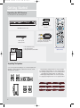
1
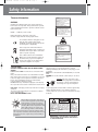
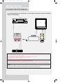
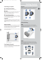
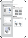
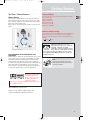
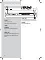
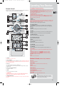
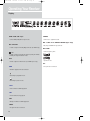
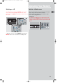
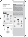
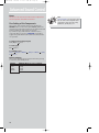
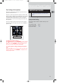
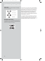
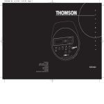
DPL907VD-EN
receiver
4/1/04
6:28 PM
Page 2
THOMSON
46, quai Alphonse Le Gallo
92648 Boulogne
Cedex FRANCE
www.thomson.net
55943670
DPL907VD-EN
receiver
4/1/04
6:28 PM
Page 3
u s e r
m a n u a l
DPL907VD
It is important to read this instruction book prior to using your new product for the first time.
wait for translation
wait for translation
wait for translation
wait for translation
DPL907VD-EN
receiver
4/1/04
6:28 PM
Page 4
Safety Information
Thomson Information
CAUTION!
Invisible laser radiation when open. Avoid exposure to
beam. Class 1 laser product. This system must be opened
only by qualified technicians to prevent accidents caused
by the laser beam.
LASER λ = 780 nm, P max = 5 mW
Rating Information: At bottom of the unit
this unit comply with the existing requirements
ADVARSEL!
USYNLIG LASERSTRÅLNING VED ÅBNING NAR
SIKKERHEDSAFBRYDERE ER UDE AF FUNKTION.
UNGDÅ UDSAETTELSE FOR STRÅLNING.
VORSICHT!
UNSICHTBARE LASERSTRALUNG
WENN ABDECKUNG GEÖFFNET UND SICHERHEITS–
VERRIEGELUNG ÜBERBRÜCKT.
NICHT DEM LASERSTRAHL AUSSETZEN!
CAUTION – INVISIBLE LASER RADIATION
WHEN OPEN AND INTERLOCKS FAILED OR
DEFEATED. AVOID EXPOSURE TO BEAM.
ATTENTION – RAYONNEMENT LASER INVISIBLE
DANGEREUX EN CAS D'OUVERTURE ET LORSQUE
LA SECURITE EST NEUTRALISEE.
EXPOSITION DANGEREUSE AU FAISCEAU.
In accordance with the rating plate of the
unit, this unit complies with current
standards concerning electrical safety and
electromagnetic compatibility.
Please respect the environment Before
throwing any batteries away, consult your
distributor who may be able to take them
back for specific recycling.
Have a Blast- Just Not in Your Eardrums
Make sure you turn down the volume on
the unit before you put on headphones.
Increase the volume to the desired level
only after headphone are in place.
For UK Only
CONNECT THE MAIN LEAD INTO AC MAINS POWER
SOCKET
POWER SUPPLY 230V. It must not be connected to D.C.
mains.
Note; The mains lead of the set is fitted with a molded
plug. If the mains socket are not compatible or if for any
reason the plug is removed please follow the directions
below. The molded plug cannot be rewired and if
removed must be disposed of safely.
DO NOT under any circumstances plug the severed plug
into any mains socket as this could result in electric shock.
Important: If the plug is removed, rewire the new plug
as follow:
The wires in the mains plug are coloured in accordance
to the following code:
BLUE = NEUTRAL/BROWN = LIVE
This product incorporates copyright protection technology that is protected by
method claims of certain U.S. patents
and other international property rights
owned by Macrovision Corporation and
other rights owners. Use of this copyright protection technology must be authorized by
Macrovision Corporation, and is intended for home
use only unless otherwise authorized by Macrovision
Corporation. Reverse engineering or disassembly is
prohibited.
CLASS 1 LASER PRODUCT
LASER KLASSE 1
APPAREIL A LASER DE CLASSE 1
LUOKAN 1 LASERLAITE
KLASS 1 LASERAPP ARAT
VARNING–
OSYNLIG LASERSTRÅLNING NÄR DENNA DEL
ÄR ÖPPNAD OCH SPÄRRAN ÄR URKOPPLADE.
BETRAKTA EJ STRÅLEN.
VARO!
AVATTAESSA JA SOUJALUKITUS OHITETTAESSA
OLET ALTTIINA NÄKYMÄTTÖMÄLLE.
LASERSÄTEILYLLE ÄLÄ KATSO SÄTEESEEN.
If the colours of the wires in the mains lead of this
apparatus may not correspond with the coloured
markings identifying the terminals in your plug, proceed
as follows:
BLUE wire to the terminal coded N (Neutral) or coloured
black.
BROWN wire to the terminal coded L (Live) or coloured
red.
DO NOT make any connection to the
terminal in the plug which is marked by
the letter E or by the earth symbol or
13A
coloured green or green and yellow.
A fused plug must be fitted with a 13A fuse approved by
ASTA or BS1362 and fuse covers must be always be
securely replaced. If you set does not work, the fuse may
be blown.
CAUTION
RISK OF ELECTRIC SHOCK
DO NOT OPEN
THE LIGHTNING
FLASH AND ARROWHEAD WITHIN THE
TRIANGLE IS A
WA R N I N G S I G N
ALERTING YOU OF
"DANGEROUS
VOLTAGE" INSIDE
THE PRODUCT.
CAUTION: TO REDUCE THE
RISK OF ELECTRIC SHOCK,
DO NOT REMOVE COVER
(OR BACK). NO USERS E RV I C E A B L E PA R T S I N S I D E . R E F E R S E RV I C I N G
TO QUALIFIED SERVICE
PERSONNEL.
THE EXCLAMATION
POINT WITHIN THE
TRIANGLE IS A
WARNING
SIGN
ALERTING YOU OF
I M P O R TA N T
INSTRUCTIONS
A C C O M PA N Y I N G
T H E P R O D U C T.
SEE MARKING ON BOTTOM / BACK OF PRODUCT
WARNING: TO PREVENT FIRE OR ELECTRICAL
SHOCK HAZARD, DO NOT EXPOSE THIS PRODUCT
TO RAIN OR MOISTURE.
DPL907VD-EN
receiver
4/1/04
6:28 PM
Page 5
Table of Content
Safety Information
CD / mp3 Player
Getting Started
Unpacking the DVD Receiver . . . . . . . . .2
Unpacking the Speakers . . . . . . . . . . . . .2
Inserting Batteries into Remote Control .3
Set Up and Maintenance of the
Receiver . . . . . . . . . . . . . . . . . . . . . . . . . .3
Protect your Components from
Overheating . . . . . . . . . . . . . . . . . . . . . . .3
Disc Information . . . . . . . . . . . . . . . . . . .3
Connecting to Audio-Visual
Components . . . . . . . . . . . . . . . . . . . . . .4
Connecting Antennas . . . . . . . . . . . . . . .5
Connecting the Speakers . . . . . . . . . . . . .6
Connecting the Subwoofer . . . . . . . . . . .6
Positioning your Speaker . . . . . . . . . . . . .7
Front Speaker Placement . . . . . . . . . . . . .7
Preferred Surround Placement . . . . . . . .8
Advanced Surround Setting . . . . . . . . . .8
Test Tone / Channel Balance . . . . . . . . . .9
Using Headphones . . . . . . . . . . . . . . . . . .9
Factory Setting . . . . . . . . . . . . . . . . . . . . .9
EN
mp3 Recommendations . . . . . . . . . . . . .30
Loading and Playing an Audio CD . . . .30
On-Screen Banner Display for CD
Playback . . . . . . . . . . . . . . . . . . . . . . . . .32
On-Screen Display for mp3 playback
. . . . . . . . . . . . . . . . . . . . . . . . . . . . .35-36
JPEG CD
On-Screen Display for JPEG CD . . . . . . .37
Radio
Operating the Radio . . . . . . . . . . . . .38-39
Troubleshooting Tips . . . . . . . .40-41
Care and Maintenance . . . . . . . . .42
Operating your Receiver
Receiver Controls . . . . . . . . . . . . . .
Remote Control . . . . . . . . . . . . . . .
Display . . . . . . . . . . . . . . . . . . . . . .
Switching On/Off . . . . . . . . . . . . . .
Selection of Audio/Video Source . .
Connection of Audio/Video Source
.
.
.
.
.
.
.
.
.
.
.
.
.
.
.
.
.
.
.10
.11
.12
.13
.13
.14
.
.
.
.
.
.
.
.
.
.
.
.
.
.
.
.
.15
.16
.17
.17
Basic Playback Features . . . . . . . . .
Quick Search . . . . . . . . . . . . . . . . .
Time Search . . . . . . . . . . . . . . . . . .
Freeze Frame and Frame Advance
Slow Motion Playback (DVD only) .
Progressive Scan . . . . . . . . . . . . . . .
On-Screen Banner Display . . . . . . .
Setup Menu . . . . . . . . . . . . . . . . . .
.
.
.
.
.
.
.
.
. . .19
. . .19
. . .19
. . .19
. . .20
. . .20
. . .20
. . .25
Advanced Sound Control
Sound Enhancement Systems
Fine Setting of Components .
Fine Setting of the Speakers .
Speaker icons . . . . . . . . . . . . .
.
.
.
.
.
.
.
.
.
.
.
.
DVD Player
1
DPL907VD-EN
receiver
4/1/04
6:28 PM
Page 6
Getting Started
Unpacking the DVD Receiver
You should receive the following items:
+
+
-
PR
One pair of “AAA”
batteries
One DVD receiver unit
SURROUND
SUBWOOFER
EQ. LEVEL
AV
one video cable (single wire)
with yellow connectors
One Pig-Tail
antenna wire
• one instruction book;
• one safety leaflet;
• one Quick Connection Guide
REC
One Remote Control
(RCT311AC1)
Unpacking The Speakers
• one set of speakers including 1 set of left and right front
speakers, 1 centre speaker, 1 subwoofer and 1 set of left
and right rear speakers.
FRONT SPEAKERS
CENTER SPEAKER
SUBWOOFER
REAR SPEAKERS
(SURROUND SOUND)
2
1 X green/grey stripped wire for center speaker
1 X red/grey stripped wire for front right speaker
1 X white/grey stripped wire for front left speaker
1 X purple/grey stripped wire for subwoofer
1 X blue/grey stripped wire for rear left speaker
1 X grey/grey stripped wire for rear right speaker
DPL907VD-EN
receiver
4/1/04
6:28 PM
Page 7
Getting Started
Inserting Batteries into Remote Control
Insert two “AAA” batteries according to the + and - signs
on the battery compartment. To use the remote control,
point it directly at your receiver.
Set up and Maintenance of the Receiver
Protect your Components from
Overheating
EN
• Do not block ventilation holes in any component.
Arrange the components so that air can circulate freely.
• Do not stack components directly on top of each other.
• Allow adequate ventilation when placing your components in a stand.
IMPORTANT NOTE
• Provide spaces for sufficient ventilation as indicated
below. If the space is insufficient, the unit may overheat
resulting in malfunction and shorter life time.
10cm/4”
SUBWOOFER
10cm/4”
10cm/4”
10cm/4”
Rear
Front
5cm/2”
• Do not connect to the AC power cords until all connections are completed.
• Do not use your set immediately after transferring it from
a cold place to a warm place: there is risk of condensation.
• Do not expose your set to water and excessively high
temperatures.
• After having disconnected your set, clean the case with a
soft cloth, or with a slightly damp leather chamois. Never
use strong solvents.
Disc handling precaution:
• Do not touch the recorded surface.
• Do not use record cleaning sprays, solvent or anti-static
liquid.
• If the disc is dirty, clean it with a damp cloth and wipe
from the center out. Wipe in straight line and not in circular motion.
• Do not attach stickers, label on the disc.
• Store the disc in its case after playing.
Regional coding
Your DVD player has been designed to process regional
management information that is stored on DVD. DVD that
have different regional codes to that of your player cannot
be played. The regional code for your player is 2 (Europe,
the Middle East, South Africa, Japan). All means all regions.
When you buy a disc, check that it bears the correct logo.
• Place the receiver near the top shelf of the stand so
heated air rising from it will not affect other components.
Disc you can play
While advances have been made to ensure that your player
is compatible with the largest number of discs possible, it
cannot be guaranteed that you will be able to play discs
which might not be compatible with audio CD, VCD and
SVCD standards. In the case of writable and rewritable
discs, compatibility with this player depends on the DVD
writer, the write sofeware and the disc used.
DVD video - Digital video discs - 12 cm and 8 cm, single or doubled sided, single or dual layer. DVDs are high-density optical discs
on which high quality picture and audio are recorded by means of
digital signals.
DVD-R, DVD-RW, DVD+R, DVD+RW - Most DVD-R and DVD+R
(one recording only), DVD-RW and DVD+RW discs (rewritable).
Depending on the DVD writer and discs used. Recordings using
DVD-R and DVD+RW discs must be made in Video DVD mode.
Recordings using DVD+RW discs must be made in accordance with
the specifications for DVD+RW discs with a 4.7 GB capacity.
VCD, Video Compact Disc - CD on which you can record up to 74
minutes of VHS-quality video associated with still images, audio
tracks and interactive menu.
SVCD, Super Video Compact Disc - Most SVCDs comply with the
IEC62107 standards. SVCDs can be used to record up to 70 minutes of digital sound and images in accordance with MPEG-2 standards for video and MPEG-1 standards for audio.
Audio CDs - Audio CDs (8 and 12cm)
CD-R, CD-RW - Most CD-R (one recording only) and CD-RW
discs (rewritable). This player can play most CD-R discs. CD-Rs
written during a multisession recording can also be played, provided that the session had ended before the disc is played (depending on the write software). However, depending on the condition of
the CD writer, computer and the disc used, you may find that not
all discs will play successfully. When playing a CD-R disc, it is completely normal for the unit to take up to 30 seconds to recognize
the disc before starting to play. If the disc is not recognized
after a period of 30 seconds, remove the disc and then insert it
again.
• Irrespective of the actual recording capacity of the CD-R, do
not use its full capacity.
• CD-Rs should be preferably used instead of CD-RWs (rewritable
CDs) as, in certain cases, CD-RW playback may be faulty.
• Use reliable, good-quality CD write software.
• Close all other applications on the computer to ensure reliable
CD-R disc recording.
Disc you cannot play
DVD-ROM, DVD RAM, CDV, SACD, DVD Audio (High resolution tracks). Data
part of CD Extra, disc with non standard shape (e.g. heart), disc with region
code different from the one specified on the back of the unit.
3
DPL907VD-EN
receiver
4/1/04
6:28 PM
Page 8
Getting Started
Connecting to Audio-Visual Components
It is recommened that you should only use one kind of connection method listed below.
(SCART recommended)
VCR
TV
TO AUDIO OUT (VCR)
S-VIDEO IN (TV)
VIDEO IN (TV)
SCART IN (TV)
1
TO AUDIO OUT (SAT)
SAT
Setup video output
You can select either S-video or SCART as your video output (default is SCART). Try power off the unit and turn it on
again if you see any picture distortion on the TV.
When S-video output is selected, SCART will only provide composite video signal.
When SCART output is selected, S-video ouput will be disabled.
Composite video signal is always available.
SCART video output (SCART cable is not supplied with this unit)
SCART video terminal provides the best quality for video signal. If there is no SCART socket is available on your TV
set, check whether your TV has another Video socket (Composite, S-video) that you can use to connect your player.
S-video
S-video provides a better connection for the video portion of the signal than composite video (yellow color terminal). When
connecting S-video cable, a Composite video cable (yellow RCA connector) must also be used.
4
DPL907VD-EN
receiver
4/1/04
6:28 PM
Page 9
Getting Started
Connecting the Antennas
Tip:
• For FM reception, extend antenna to its
full length and arrange the antenna at different parts of the room until the reception is optimized.
EN
The FM antennas connect to the FM terminals on the system’s back panel.
They must be hooked up in order to have clear reception.
5
DPL907VD-EN
receiver
4/1/04
6:28 PM
Page 10
Getting Started
Connecting the Speakers
Speaker Polarity
When connecting the speakers, make sure the polarities
(“+” speaker wire to “+” on the receiver) of speaker wires
and terminals are matched. If the cords are reversed, the
sound will be distorted and lack bass (“out of phase”
effect).
Do not ground the output line, it will cause damage to the
speaker.
Speakers
There are 6 speakers equipped with the unit (2 front, 1 center, 2 rear, 1 subwoofer). In order to enjoy good surround
effects all six speakers need to be connected to the receiver
Speaker cords
1 for each speaker, is needed
for connection. Press down
the tab to open the terminal
and insert the wire. Release
tab to lock wire in the terminal.
To ease speaker connections,
the speaker cords and the terminals are color-coded. (please
refer to the diagram)
Connect the speaker wire to
the back of L, R front speakers
and to the corresponding
color terminals on the rear of
the receiver. Do the same for
center speaker, rear speakers
and the subwoofer.
6
Antenna and Speaker
Wire Connection
Push Speaker terminal tab
down to insert wire.
Release tab to lock wire in
the terminal.
NOTE: Make sure the insulation
is completely removed from the
ends of the Antenna and
speaker wires at all connection
points.
DPL907VD-EN
receiver
4/1/04
6:28 PM
Page 11
Getting Started
Positioning your speaker
Alignment
Align the center speaker evenly with (A), or slightly behind
(B), the left and right speakers, but not ahead of them.
1 Left, Right (Front Speakers)
They carry primarily music and sound effects.
2 Center
In surround mode, the center speaker carries much of the
dialogue as well as music and effects. It should be set
between the left and right speakers.
3 Surround (Rear Speakers)
Their overall sound balance should be as close as possible
to the front speakers. Proper placement is vital to establish
an evenly distributed sound field.
Subwoofer
A subwoofer is designed to reproduce powerful low bass
effects (explosions, the rumble of spaceships, etc.) which
dramatically heightens involvement with the action on the
screen.
Courtesy Dolby Laboratories
Advanced Setting
Magnetic shielding
Angle
Speakers placed less than two feet from the TV set must be
magnetically shielded in order to prevent picture distortion. Front and center speakers provided with this unit are
magnetically shielded to protect your TV set.
Placing the left and right speakers to form a 45-degree
angle with your favorite viewing position will duplicate the
soundtrack mixer's perspective.
It is not recommended to place the rear speakers and subwoofer near the TV set.
3
1
2
Courtesy Dolby Laboratories
1
3
Courtesy Dolby Laboratories
Front Speaker Placement
Even if you can't duplicate this ideal home theater setup
exactly, the following suggestions for speaker placement
will help you to get better results.
Height
The mid- and high-frequency drivers of the three front
speakers should be as close as possible to the same height.
This often requires placing the center speaker directly atop
(A) or beneath (B) the TV set.
A
B
Courtesy Dolby Laboratories
7
EN
DPL907VD-EN
receiver
4/1/04
6:28 PM
Page 12
Getting Started
Preferred surround placement
Location
If possible, place surround speakers to either side of the listening area, not behind it.
Advanced Setting
Alternative Surround Placement
Rear wall
If rear wall mounting is the only choice, aim the speakers at
each other (A), towards the front (B) or even towards the
sidewalls (C, D). Experiment with placement until surround
sounds seem to envelop you, rather than coming from
behind you.
Courtesy Dolby Laboratories
Height
If space permits, install surround speakers 2-3 feet above
viewers. This helps to minimize localization effects.
Courtesy Dolby Laboratories
No adjacent walls
Surround speakers can go on stands facing each other to
approximate the preferred sidewall mounting (A), or to the
sides or rear of the viewing area aimed upwards. In the latter case, they can go right on the floor, or preferably, a few
feet off the floor such as on end tables (B).
Courtesy Dolby Laboratories
Aiming
Aiming surround speakers straight across the room, not
down at viewers, helps create a more open, spacious surround sound field.
Courtesy Dolby Laboratories
Courtesy Dolby Laboratories
8
DPL907VD-EN
receiver
4/1/04
6:28 PM
Page 13
Getting Started
Test Tone / Channel balance
Factory Setting
Channel balance
Your receiver is equipped with a test signal generator for
balancing the channels. As the signal "travels" from channel to channel, adjust the level controls until each channel
plays at the same loudness level.
Please refer to “Fine setting your speaker” section for more
details.
The unit is preset to the following setting when you first
turn on the power.
Function = TUNER
Volume setting = 25
Bass & Treble = 0 dB
Channel level = 0 dB
Subwoofer = STRONG
EN
Restore to default settings
You can always restore all settings back to its original state.
When the receiver is in ??? mode, press the following
sequence on the main unit to restore all settings back to
default :
???
???
???
6
5
4
Courtesy Dolby Laboratories
Level adjustment & surround channel level
expectation
Even though you adjust the surround channel to be as loud
as the others on the test signal, you'll find that on actual
program material the surround channel is usually much
lower than the front. Don't be tempted to re-adjust the
surround level; program producers use surround mostly for
subtle atmosphereics and ambience, and only rarely for
special effects. A good surround mix doesn't call attention
to itself; if it did, it would soon become distracting.
Manufactured under license from
Digital Theater Systems, Inc. US Pat. No.
5,451,942, 5,956,674, 5,974,380,
5,978,762 and other world-wide patents
issued and pending. "DTS" and "DTS Digital Surround"
are registered trademarks of Digital Theater Systems,
Inc. Copyright 1996, 2000 Digital Theater Systems, Inc.
All Rights Reserved.
Note:
All preset radio stations and surround
sound setting will be lost after the factory setting is restored.
Dolby Digital
Manufactured under license
from Dolby Laboratories.
“Dolby”, “Pro Logic” and
the double-D symbol are
trademarks of Dolby
Laboratories. Copyright 1992-1997 Dolby Laboratories,
Inc. All Rights Reserved.
Will add DOLBY PL II picture later
Dolby, Pro Logic, and the double-D symbol are
registered trademarks of Dolby Laboratories.
9
DPL907VD-EN
receiver
4/1/04
6:28 PM
Page 14
Operating Your Receiver
1
2
3
4
5
6
7
8
9
Receiver Controls
1. ON / ECO
• To turn on or off the receiver.
7. PRESET + / NEXT
• To go to the next preset memory location in tuner mode.
• To skip to the next track in CD mode and the next chapter in
DVD mode (only during playback).
2. OPEN / CLOSE
• Press to open / close the CD compartment door.
8. PLAY/PAUSE
To start and pause DVD/CD playback.
3. SOURCE
• To select input source. For example, DVD/CD, VCR, etc.
9. VOLUME
Turn the knob to adjust volume level.
4. SUBWOOFER
• Press to toggle among different subwoofer mode.
5. STOP
To stop DVD/CD playback.
6. PRESET - / PREV
• To move back to the beginning/previous preset memory
location in tuner mode.
• To skip to the beginning/previous track in CD mode and the
beginning/previous chapter in DVD mode (only during
playback).
10
DPL907VD-EN
receiver
4/1/04
6:28 PM
Page 15
Operating Your Receiver
Remote Control
Please be sure you have inserted the batteries into the remote
control. You can test it by pressing any button.
1
2
20
3
4
PR
5
11
21
9
7
17
19
SURROUND
EQ. LEVEL
SUBWOOFER
6
16
15
- press OK will enter function setting mode.
- Press OK again for dimmer and sleep function.
- When the display shows the setup you want to change (dimmer, sleep, etc),
press the UP and DOWN buttons to make changes.
• In DVD/CD/JPEG mode, press the arrow buttons to navigate OSD menu,
and press OK to validate selection.
8. Number Buttons
• In Tuner mode, to select a preset station.
• In DVD/CD mode, enable pull down menu by INFO, then press the arrow
buttons to select field to be adjusted. Press the Number buttons to direct
input the settings (e.g. CD track)
9. MENU
• In Tuner mode:
- Press to store desired frequency in memory. The flashing icon “PRESET” will
appear in display. Input your desired channel number while the word is still
flashing and the frequency will be stored.
• In DVD mode, press for menu setup for DVD title.
10. Operation Buttons
• Press DVD/CD on the remote to enter DVD/CD mode. In DVD/CD mode,
you can press the operation buttons to perform actions such as play, stop,
pause, etc.
11. CLEAR
• When in OSD menu, press to return to the root menu.
12. AUDIO
• In Tuner mode, press this button to switch from ST to MONO mode and
vice-versa.
• In DVD mode, press to select different audio channel (if available).
13. ANGLE (DVD only)
• Press to select different screen display angles.
8
15. INFO
• Press to display playback information.
13
AV
12
6
10
14
REC
18
14. ZOOM (DVD / JPEG only)
• Press to select the zoom ratio.
2
16.TITLE•GUIDE
• Press to go to the title menu at DVD mode.
17. SURROUND
• Press to change the surround sound settings.
18. PLAYMODE
• Press to toggle between different playmodes. (Repeat chapter, etc.)
19. EQ. LEVEL
• Press to toggle between equalizer setting, BASS/TRE setting and channel
setting.
- In equalizer setting mode, use LEFT/RIGHT to change the setting.
- In BASS/TRE setting mode, use UP/DOWN to adjust level setting.
- In channel setting mode, use LEFT/RIGHT to select channel, and use
UP/DOWN to adjust level setting.
20. TV
• Press to select the television.
1. ON•OFF
• To turn on or off the receiver.
2. Source Buttons
• To turn on and select various audio/video sources. (The button functions will
be re-arranged when in AUX 1 and AUX 2 mode, the function may vary depending on the compnents used)
3. PR+, PR• To select programmed stations in TUNER mode.
• To skip to the next or previous chapter, track or image in DVD, CD, mp3
and JPEG mode.
Functions in TV mode (available when using a THOMSON TV)
3. PR+, PR• Press to change channel.
7. LEFT / RIGHT
• Press to use the zoom function (with a 16:9 television only)
9. MENU
• Press to exit a menu.
4. VOL+, VOL- (Volume Buttons)
• To adjust the volume.
15. INFO (Yellow)
• Press to obtained information about the channel.
5. MUTE
• To mute / unmute all audio outputs.
16. TITLE.GUIDE (Blue)
• Press to display the programmed guide.
6. SUBWOOFER
• Selects among subwoofer output level (SOFT SUBWOOFER, BALANCED
SUBWOOFER, STRONG SUBWOOFER, POWERFUL SUBWOOFER).
21. GO BACK
• Press to return to the channel watched before last.
7. Adjustment Buttons
• In TUNER mode, press the arrow buttons to tune up or down the radio frequencies.
Note:
The coloured buttons can also be used to access the
Teletext topics indicated in colour (if your television
has the Teletext function available.)
11
EN
DPL907VD-EN
receiver
4/1/04
6:28 PM
Page 16
Operating Your Receiver
Display
DVD / VCD / CD / mp3
STEREO
• Unit in DVD, VCD, CD or mp3 mode.
• Tuner stereo signal detected.
REP 1 / REP / A.B. / REPEAT FOLDER (mp3 only)
D I G I TA L
• CD, mp3 and DVD in repeat mode.
• Audio output is in Dolby Digital mode. (For DVD only)
KHz / MHz
• Tuner frequency unit.
PL
• Audio output is in Dolby PL II Movie, Dolby PL II Music
or Dolby Prologic Emulation mode.
DTS
• Speaker Icons.
• Audio output is in DTS mode. (For DVD input only)
RND
• Random playback mode activated.
• Currently in playback mode.
• Currently in pause mode.
TITLE
• Title number for DVD playback.
TRK
• Track number being played.
CHP
• Chapter number for DVD playback.
PROG.
• Program mode is activated.
12
SLP
• Sleep mode is activated.
DPL907VD-EN
receiver
4/1/04
6:28 PM
Page 17
Operating Your Receiver
Switching on /off
Selection of Audio source
• To switch on the receiver, press ON/ECO on the receiver
once to wake up from standby mode. Press one of the
source buttons or ON/OFF on the remote control to turn on
the receiver.
When one of the audio source is selected, the audio input
corresponding to the name will be activated.
The receiver acts as a switching device between all the
sources that are plugged into it.
Example 1:
If you connect a MD player to the AUX 1 input on the
receiver and press SOURCE until “AUX 1” shows on the
display. You will be able to have the signal from the MD
player.
FWD
REV
PR
AUX 2
VCR
AUX 1
SAT - CABLE
PR
• When the receiver is on, press ON/OFF on the remote or
ON/ECO on the receiver to return to the standby mode.
13
EN
DPL907VD-EN
receiver
4/1/04
6:28 PM
Page 18
Operating your Receiver
Connection of Audio/Video source
You can connect up to 2 audio sources to this
amplifier:
Source button
(remote control)
Corresponding connector
(receiver back panel)
-
built-in
built-in
AUX 1 IN
AUX 2 IN
DVD/CD
TUNER
AUX 1
AUX 2
When a source is selected, the source name is shown on the
display.
14
Note:
1. Your receiver has a built in tuner. Just
connect the appropriate antenna to the
back of the receiver and you will be able
to listen to radio stations. (See details in
Tuner section)
2. The receiver is also equipped with DVD/CD player. Press
the SOURCE button on the main unit or DVD/CD button on
the remote to activate the feature.
3. Other sources (Tapes,etc) can be connected to this unit
provided that the connections are compatible.
4. Refer to the "Connecting To Audio-Visual Components"
section for details on connection.
DPL907VD-EN
receiver
4/1/04
6:28 PM
Page 19
Advanced Sound Control
Sound Enhancement Systems
Dolby Digital
This receiver is equipped with several built-in sound
enhancement systems.
The Dolby Digital mode lets you enjoy full digital
surround from software processed in the Dolby Digital format. Dolby Digital provides better sound quality and a
more powerful presence than conventional Dolby
Surround.
Dolby Pro Logic II
The Pro Logic II mode uses the built-in circuit to steer the
Left, Center, Right and Surround left and right channel
audio signals and uses all five speakers to play both stereo
and Dolby Pro Logic program source, such as TV and VCR.
Dolby Pro Logic II includes Dolby Pro Logic II Movie, Dolby
Pro Logic II Music and Dolby Pro Logic Emulation.
You can use this mode to suit any stereo program source
to enjoy multi-channel sound experience).
This unit is equipped with Dolby Digital 5.1-channel so
that you can enjoy enhanced full digital surround sound.
Different from Dolby Pro Logic in that only four channels (
Front Left, Front Right, Centre and Rear ) are used, the new
system provides stereo separation of the rear speakers
(Rear-Right, Rear-Left ). Adding the to the 5 channels the
subwoofer channel for bass sounds (counted as 0.1 channel)
results in 5.1 channels (or 6 Channels) that bring you the
most sophisticated Dolby Digital sound enjoyment.
Digital Theater Systems (DTS))
Front Left Speaker
Center Speaker
Front Right Speaker
DTS is a digital surround system which delivers six channels
of master-quality, 20-bit audio. It offers five full-range
channels plus a special low frequency effect (LFE) channel
for subwoofer, resulting in what is commonly known as 5.1
channels. It can be applied with existing 5.1 speaker configurations.
DTS is available in DVD and CD mode.
Subwoofer
Listening
Zone
Front Left Speaker
Center Speaker
Rear Right Speaker
Rear Left Speaker
Dolby 3 Stereo
Subwoofer
The 3 Stereo mode will redirect the Surround signals to the
front left and right speakers when only the front and
center speakers are used.
Listening
Zone
Rear Left Speaker
Front Left Speaker
Front Right Speaker
Center Speaker
Rear Right Speaker
Front Right Speaker
Listening
Zone
15
EN
DPL907VD-EN
receiver
4/1/04
6:28 PM
Page 20
Advanced Sound Control
Stereo
The Stereo mode uses the two main channel outputs from
the front speakers and subwoofer channel.
Fine Setting of the Components
The receiver can be directly turned on by pressing the
SOURCE buttons on the remote (like DVD/CD), which also
selects the best surround sound mode. The default surround
modes for different components are as below.
If you want to enjoy multi-channel sound from stereo
sources like CD, you can press SURROUND repeatedly to
toggle among the different surround modes and select the
one you want.
For Digital Signal (Dolby Digital)
Dolby Digital
Stereo
For DTS Signal
DTS
Stereo
For STEREO Signal
Stereo
Dolby PL II MOVIE
PL
Stereo
Dolby PL II MUSIC
Dolby
Default Settings
The receiver will keep the last selection in memory as long
as it doesn’t enter standby mode.
SOURCE
AUX 1
AUX 2
TUNER
DVD/CD
16
DEFAULT INPUT (as seen on display)
Analog
Analog
Built-in
Built-in
Note:
AUX 1 and AUX 2 are just generic names.
You can connect other compatible audio
components to these inputs like TAPE,
MINI DISC, CD-RW player, etc.
DPL907VD-EN
receiver
4/1/04
6:28 PM
Page 21
Advanced Sound Control
Fine Setting of the Speakers
All the basic settings have already been presetted for the
speakers included in the box.
However, to make the surround sound more effective and
suit the acoustic conditions in your listening room, you may
need to delay the signal coming from some of the speakers. Channel delay compensates for center or surround
speakers that are closer to the listening position than the
front speakers.
You may setup the speakers channel by channel: while in
stop mode, enter the setup menu, then choose SOUND for
speaker setup.
IMPORTANT NOTE
EN
• Always use the subwoofer for optimum sound
quality.
Advanced Setting
Factory Default Setting
The receiver speaker distance default settings are the
following:
Front speakers (L/R)
Center speaker (Cch)
Rear speaker (SUR)
4.5 m
4.5 m
3m
Front Left Gain Control
0 dB
To change the speaker distance
In the DISTANCE menu, press UP/DOWN to select a speaker.
press OK to select the speaker channel which you want to
adjust, then press UP/DOWN to adjust the distance from
the front, rear and center speakers individually.
To test the speaker setting and change the speaker
level
In the TEST TONE menu, a short noise will come from each
speaker respectively, press UP/DOWN to configure the currently playing speaker.
17
DPL907VD-EN
receiver
4/1/04
6:28 PM
Page 22
Advanced Sound Control
Speaker Icons
The receiver shows the speakers’ settings on the display
with the following icons:
Front Speakers
Center Speakers
It is important to note, however, that not all Dolby Digital
sources are encoded with the full complement of five channels plus subwoofer. Speaker icons show how many and
which speaker you have enabled (See “Fine Setting of the
Speakers”) and the letters inside the speaker icons show
which channel is present in the source information. For
example, the diagram shown means you have all five
speakers and subwoofer enabled and the digital sources
you played have five channels plus subwoofer complemented. (Dolby Digital 5.1 Channels)
Surround Speakers
Subwoofer
Displaying Program Formats
When a digital source starts playing, the receiver automatically switches to proper surround mode and provides setting information via the speaker icons located on the righthand side of the display. (See diagram)
18
* “S” stands for subwoofer. The indication “S” appears if
the digital source contains subwoofer information. In this
case, the bass signal will be delivered to the subwoofer,
offering more dynamic deep bass sound effects. If the letter
is flashing, the signal is either too weak or just gone.