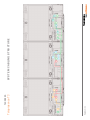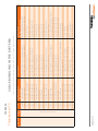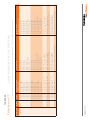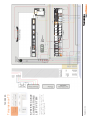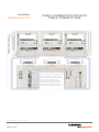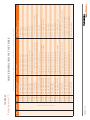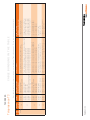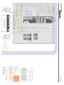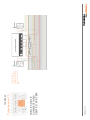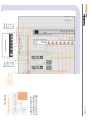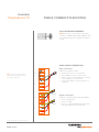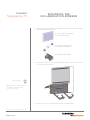
1
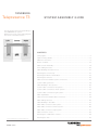
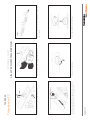
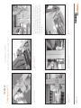
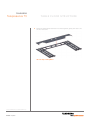
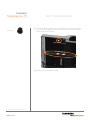
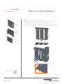
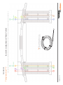
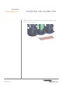
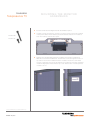
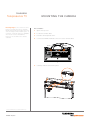
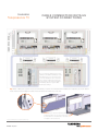
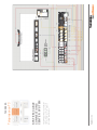
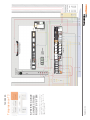
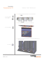
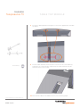
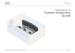
TANDBERG Telepresence T3 system assembly guide 119078.01 TELEPRESENCE T3 SYSTEM ASSEMBLY 12.08 PAGE 1 / 5 8 Important information regarding room dimensions The information contained in this document applies to an optimally sized immersive room. For rooms of other dimensions, the information in this document should be regarded as guidelines only and dimension information should be adapted accordingly, wherever applicable. This document is confidential and remains proprietary to Tandberg Telecom AS (“Tandberg”). Without Tandberg’s prior written approval, this document, either in whole or in part, may not be reproduced in any form or by any means, disclosed to others outside the Client’s organisation or used for any purpose whatsoever other than for evaluatory purposes by the Client. All information, descriptions, examples and calculations contained in this document are for guidance purposes only and should not be treated as definitive. Whilst all reasonable care has been taken to ensure that the information contained in the presentation is accurate and not misleading, Tandberg shall not be liable for any loss resulting from reliance placed on the information contained in this document. TANDBERG WORLD HEADQUARTERS Philip Pedersens vei 20 1366 Lysaker, Norway Tel: +47 67 125 125 Fax: +47 67 125 234 Video: +47 67 126 126 E-mail: [email protected] 1212 Avenue of the Americas 24th Floor New York, NY U.S.A. 10036 Tel: +1 212 692 6500 Fax: +1 212 692 6501 Video: +1 212 692 6535 E-mail: [email protected] www.tandberg.com 119078.01 TELEPRESENCE T3 SYSTEM ASSEMBLY 12.08 PAGE 2 / 5 8 TANDBERG Telepresence T3 system assembly guide This document shows the assembling of the TANDBERG T3 system. References to left, center and right parts are shown in illustration below. Contents Ceiling lights............................................................................................................4 Light mounting details.............................................................................................6 Table Floor structure................................................................................................8 bottom modules....................................................................................................14 Table Column Assembly........................................................................................19 Floor cabling structure...........................................................................................20 Cable bundling Structure in Floor..........................................................................21 Mounting the Column tray.....................................................................................22 Mounting the Monitor Assemblies........................................................................23 Mounting the Camera............................................................................................26 Cable Connection details system connections......................................................28 System cabling structure.......................................................................................29 Cable bundling in the systems..............................................................................30 System cable connections left system..................................................................32 System cable connections center system.............................................................33 System cable connections right system................................................................34 Table Top Module..................................................................................................35 Cable Connection details table connections..........................................................39 Table cabling structure...........................................................................................40 Cable bundling in the table....................................................................................41 Table cable connections left system.....................................................................45 Table cable connections center system................................................................46 Table cable connections right system...................................................................47 Table Connection notes.........................................................................................48 Mounting the collaboration screens......................................................................49 Mounting the TCU.................................................................................................54 119078.01 TELEPRESENCE T3 SYSTEM ASSEMBLY 12.08 PAGE 3 / 5 8 TANDBERG Telepresence T3 Ceiling lights Unpack the box marked ‘Main Lighting T3’. The box contains the Telepresence T3 Ceiling lighting modules. The rear ceiling lighting consists of seven 640 mm spot light armatures mechanically fastened together and parallel wired together. Recommended positioning for the rear ceiling lighting are rear edge 5 cm / 2” from the inner rear wall and 228 cm / 7’ 5 3⁄4” from the floor. ) The front ceiling lighting consists of four 450 mm spot light armatures plus three fluorescent light armatures mechanically fastened together and parallel wired together. Recommended positioning for the front ceiling lights is rear edge 200 cm / 6’ 6 7⁄10” from inner rear wall and bottom edge 228 cm / 7’ 5 3⁄4” from the floor). Ceiling attachment by means of hang wires provided with lighting. Anchor method in ceiling will depend on ceiling structure and composition. You may want to consult an architect or building engineer to define the suitable mounting method. The lights are to be connected to a switch as described in the document TANDBERG Telepresence T3—Room Requirements. Power supply requirements can be found in the document TANDBERG Telepresence T3—Room Requirements. 228 cm 7’ 5 3⁄4” 119078.01 TELEPRESENCE T3 SYSTEM ASSEMBLY 12.08 PAGE 4 / 5 8 TANDBERG Telepresence T3 Ceiling lights Note! These items are included in the Immersive Room Package. What to unpack: Unpack the box marked • Main Lighting T3 Box contents: • The box contains 6 Fluorescent lightbulbs US: 21W 830 EU: 39W 830 11 35W Halogen lightbulbs. The rear ceiling lighting consists of seven 640 mm spot light armatures mechanically fastened together and parallel wired together. (Rear edge 5 cm / 2” inner rear wall and 228 cm / 7’ 5 3⁄4” from the floor. ) The front ceiling lighting consists of four 450 mm spot light armatures plus three fluorescent light armatures mechanically fastened together and parallel wired together. (Rear edge 200 cm / 6’6 7⁄10” from inner rear wall and bottom edge 228 cm / 7’ 5 3⁄4” from the floor). Ceiling attachment by means of hang wires provided with lighting. Anchor method in ceiling will depend on ceiling structure and composition. 119078.01 TELEPRESENCE T3 SYSTEM ASSEMBLY 12.08 PAGE 5 / 5 8 Unscrew the light bezel. Use the provided 4mm bolts ad plastic nuts to fasten the seven lights together in one continuous row. PAG E 6/58 119078.01 TELEPRESENCE T3 SYSTEM ASSEMBLY 12.08 Trim off excess wire to approximately 8cm / 3” Ceiling light Light mounting details Thread hang wires through push fasteners. Telepresence T3 TANDBERG Insert light bulb. Reinstall light bezel. Press in the chrome colored end plates to cap off each row of lights. The four spotlights and the three fluorescent lights are physically fastened together with two M4x40 screws and knurled plastic nuts. Blue=N Green=GND Brown=L PAG E 7/58 119078.01 TELEPRESENCE T3 SYSTEM ASSEMBLY 12.08 Remove screw, plastic retainer and alloy protective guard for wiring access. Ceiling light Light mounting details Remove screw, plastic retainer and alloy protective guard for wiring access. Telepresence T3 TANDBERG Use the chrome plates to cap off the ends of the far right and far left spotlight boxes in the two rows of lights. Remove the five wire factory installed lead from the fluorescent light armature. (This is only used with dimming) Use a 20cm piece of the three wire lead to couple the adjacent spot/fluorescentlights together. There should be many extra meters of the three wire leads from the spotlights after they are clipped to the correct length. TANDBERG Telepresence T3 Table Floor structure Caution! Make sure power is disconnected before any cables are connected or disconnected. Unpack the box marked ’T3 Table Floor Structure and brackets’. The box contains the parts shown in the below Fig. Gently unpack the cover plates and place them in the lid of the box, with the packaging foam to ensure they are not damaged. Coverplate Front right Coverplate Right Coverplate Center Coverplate Front left Coverplate Left Coverplate End Coverplate End Bottom Frame center Bottom Frame right Bottom Frame left Monitor bracket (3×) Module angle plate (2×) Cable channel (2×) Nut plate (8×) Splitter bracket small (2×) 119078.01 TELEPRESENCE T3 SYSTEM ASSEMBLY 12.08 PAGE 8 / 5 8 Splitter bracket big (2×) TANDBERG Telepresence T3 Note! The system has been designed for rooms with entrance door opening outwards. Should you for any reason be unable to fulfill this requirement make sure you position the system so that it will not block the door from opening completely. Table Floor structure Do as follows: 1. Begin by placing the ‘bottom frame center’ centered on the floor, appr. 4.2 m (13’ 9”) from the rear (white) wall. The distance between the white and the blue wall is 140 mm (5½”). r oo D 4.06 m 13’31⁄2” 4.2 m 13’ 9” to wall 119078.01 TELEPRESENCE T3 SYSTEM ASSEMBLY 12.08 PAGE 9 / 5 8 TANDBERG Telepresence T3 Table Floor structure 2. Unpack the bag containing screws, nuts and plates, located in the box marked T3 Brackets kit. Contents should be as follows: 6 pcs Nut M6 (g) (Flange type) te spla him S 2 × 28 pcs Screw M4×12 (h) (Pan) ning oi 2 × J e plat 4 pcs Screw M4×40 (i) 12 pcs M10×30 (e) 62 pcs M6×10 (c) 6 pcs Screw M3×10 (j) 36 pcs M8 nut (b) 34 pcs M6 nut (a) 8 × nut (a) M6 119078.01 TELEPRESENCE T3 SYSTEM ASSEMBLY 12.08 PAGE 1 0 / 5 8 6 pcs M4×12 (f) 32 pcs M4×8 (d) 3. Then place the Bottom frame right on the right side of the Bottom frame center. Fasten with 4 pcs. of nut (a). Repeat for left side. TANDBERG Telepresence T3 Table Floor structure 4. Please make sure that the distance to the wall is constant. If necessary, mark the position with a piece of tape or similar. Tape 5. Remove the protective film along the edges on the Coverplate center (highlighted in picture). Repeat for the other two coverplates. 119078.01 TELEPRESENCE T3 SYSTEM ASSEMBLY 12.08 PAGE 1 1 / 5 8 TANDBERG Telepresence T3 Table Floor structure 6× screw (c) M6×10 6. Fasten the Coverplate center to the coverplate front left, using the Joining plate and the Shims plate. 2× nut (a) M6 7. Fasten with 3 pcs of the M6×10 screw (c) and one nut Note! The plates are shown upside down for clarity. 8. Repeat on the right side, with the right cover plate. 119078.01 TELEPRESENCE T3 SYSTEM ASSEMBLY 12.08 PAGE 1 2 / 5 8 TANDBERG Telepresence T3 Table Floor structure 9. When the three plates have been mounted together, gently sink them onto the floor structure. Do not step on the plates! 119078.01 TELEPRESENCE T3 SYSTEM ASSEMBLY 12.08 PAGE 1 3 / 5 8 TANDBERG Telepresence T3 Tip! The procedure outlined in this chapter suggests that you mount all three bottom modules before you mount the monitors on top of these modules. bottom modules 1. Unpack the left system and take out the left Bottom module. Dismount the top screw on the right side in addition to the cable hatch cover. As an alternative, you may prefer to mount each bottom module / monitor set completely before proceeding to the next bottom module / monitor. Caution! Regardless of the method preferred, the cables between the DNAM modules and the monitors must be connected to the DNAM modules before you mount the monitors. The cables are: Cable 117850 to the left DNAM Cable 117852 to the center DNAM Cable 117856 to the right DNAM 2. The following cables must be disconnected and removed: • 112083 Ethernet Cable • 112980 Power Cable (main in) • 115233 PC Connection Cable (Video/audio in) • 117083 Main Speaker Cable (top of amplifier) • 117087 D-sub Monitor Control Cable (USB-DSUB) • 118315 External Microphone Cable • 117084 Audio RCA Cable (Codec to amplifier). 4 × nut (b) M8 Note! Retain the DVI to HDMI cable between monitor and codec plus three power cables. 119078.01 TELEPRESENCE T3 SYSTEM ASSEMBLY 12.08 PAGE 1 4 / 5 8 3. Fasten by fastening 4 × nuts (b). TANDBERG Telepresence T3 119078.01 TELEPRESENCE T3 SYSTEM ASSEMBLY 12.08 PAGE 1 5 / 5 8 bottom modules TANDBERG Telepresence T3 bottom modules 4. Unpack the center system. Dismount the top screw and the cable hatch cover on both sides of the module. Note! Screws and cable hatch covers must be removed before the next module is mounted. 5. In addition, disconnect and put away the following cables: 4 × nut (b) M8 • 112083 Ethernet Cable • 112980 Power Cable (main in) • 115233 PC Connection Cable (Video/audio in) • 117083 Main Speaker Cable (top of amplifier) • 117087 Monitor Control Cable (USB-DSUB) • 118315 External Microphone Cable Note! The 117084 Audio RCA Cable (Codec to amplifier) shall be retained for the Center module. Do not remove this cable! 6. Mount the Center bottom module to the floor structure. 119078.01 TELEPRESENCE T3 SYSTEM ASSEMBLY 12.08 PAGE 1 6 / 5 8 TANDBERG Telepresence T3 bottom modules 7. Unpack the right Bottom module. Dismount the top screw and the cable hatch cover on the left side of the module, in addition to the same cables which were disconnected in the Left module, i.e.: • 112083 Ethernet Cable • 112980 Power Cable (main in) • 115233 PC Connection Cable (Video/audio in) • 117083 Main Speaker Cable (top of amplifier) • 117087 Monitor Control Cable (USB-DSUB) • 118315 External Microphone Cable • 117084 Audio RCA Cable (Codec to amplifier) 8. Mount the right Bottom module. 4 × nut (b) M8 Caution! If you choose to open any of the lids completely, make sure you put a soft cloth or similar between the lid and the vulnerable coverplate to avoid scratches 119078.01 TELEPRESENCE T3 SYSTEM ASSEMBLY 12.08 PAGE 1 7 / 5 8 Observe that the bottom modules can be opened completely. When you do the cabling we recommend that you open the center module completely and the left and right modules partly. TANDBERG Telepresence T3 6 × nut (g) bottom modules 9. For the left Bottom module, get the splitter brackets shown above. Fasten them using 3 pcs M6 flange nuts as shown below. Then place the HDMI splitter between the brackets. Splitter Bra cket small Splitter Bra cket big 10. Repeat for the right Bottom module. 119078.01 TELEPRESENCE T3 SYSTEM ASSEMBLY 12.08 PAGE 1 8 / 5 8 TANDBERG Telepresence T3 Table Column Assembly Unpack the box marked ‘Table column Assembly’ 2× Table column 2× Column cover 2× Doorcover 4 × nut (b) M8 119078.01 TELEPRESENCE T3 SYSTEM ASSEMBLY 12.08 PAGE 1 9 / 5 8 Note! The Column covers and the Door covers shall not be mounted yet, so please place them in a spot where they won’t be damaged. 1. Mount the columns using 12 × nut b for each column, but make sure that only the two outer nuts are fastened at this point. Screw only finger-tight. 119078.01 TELEPRESENCE T3 SYSTEM ASSEMBLY 12.08 PAG E 20/58 Floor cabling structure Tip! We recommend the use of a cable fish when drawing the cables. Place cable kits 1–9 in floor structure according to the figure ”Floor Cabling Structure” (shown on the previous page). The numbers 1–9 match the cable kits 1–9 Telepresence T3 TANDBERG (Internet – Tec PC) (Videonet – Tec PC) (Module left splitter – Display Pres L) (Module left splitter – Display Pres M) (Codec M – Tec PC) (Display Video Left 1 – Tec PC) (Display Video Main – Tec PC) (Codec Left – Tec PC) (Codec Main – Tec PC) (Codec Left – Tec PC) (Codec Main – Tec PC) (Codec Right – Tec PC) (Display Video right – Tec PC) (Codec right – Tec PC) Videonet/IP – Telepresence Control Unit Videonet – Telepresence Control Unit Presentation Splitter L – Touch Collaboration Display L Presentation Splitter L – Touch Collaboration Display C Codec C – Telepresence Control Unit Main Video Display L – Telepresence Control Unit Main Video Display C – Telepresence Control Unit Codec L – Telepresence Control Unit Codec C – Telepresence Control Unit Codec L – Telepresence Control Unit Codec C – Telepresence Control Unit Codec R – Telepresence Control Unit Main Video Display R – Telepresence Control Unit Codec R – Telepresence Control Unit Cable RJ45 – RJ45 Cable RJ45 – RJ45 Cable HDMI – HDMI Cable HDMI – HDMI Cable 3,5mm split – RCA/RCA Cable 9p DSUB – 9p DSUB Cable 9p DSUB – 9p DSUB Cable 9p DSUB – 9p DSUB Cable 9p DSUB – 9p DSUB Cable RJ45 – RJ45 Cable RJ45 – RJ45 Cable 9p DSUB – 9p DSUB Cable 9p DSUB – 9p DSUB Cable RJ45 – RJ45 Cable HDMI – HDMI Cable XLR plug – Single Wires Cable XLR plug – Single Wires Cable DVI – VGA 4,5 Cable 6 × XLR – XLR Cable Power Male – Female Cable Power Male – Female Cable Power Male – Female Cable Power Male – Female Cable Power Male – Female 117875 117880 117806 117809 117826 117866 117867 117869 117870 117876 117877 117871 117868 117878 117812 117828 117829 117830 117844 117914 117915 117916 117909 117917 4 6 7 8 9 PAG E 21/58 Wall - Presentation Splitter R Wall - Power Distribution Block (T1 system Right) Wall - Presentation Splitter L Wall - Power Distribution Block (T1 system Left) Wall - Power Distribution Block (T1 system Center) Presentation Splitter R – Touch Collaboration Display R Codec C – Presentation Input Switch Codec C – Presentation Input Switch Codec C – Presentation Input Switch Codec C – Mic L1 – 2 / C1 – 2 / R1 – 2 MicroDot to XLR adapters Wall – Power Distribution Block 3 Wall – Power Distribution Block 4 (Wall – Module R Splitter) (Wall – System Right 1) (Wall – Module L Splitter) (Wall – system left) (Wall – system main) (Module right splitter – Display Pres Right 1) (Codec Main – Switch PC in Pres) (Codec Main – Switch PC in Pres) (Codec Main – Switch PC in Pres) (Codec Main – Mic (1-6)) (From wall – splitter 3) (From wall – splitter 4) Cable Power Male – Female Cable Power Male – Female 117911 117919 (From wall – splitter 1) (From wall – splitter 2) 3 Wall – Power Distribution Block 1 Wall – Power Distribution Block 2 Cable Power Male – Female Cable Power Male – Female 117912 117918 From / to device (Marking on older versions) 2 Country specific extension cords From / to device Powercable kit Bundling description [OLD description] 118610 Art.No. 1 Drawing reference 119078.01 TELEPRESENCE T3 SYSTEM ASSEMBLY 12.08 119070 From Kit No. Cable bundling Structure in Floor Place cable kits 1–9 in floor structure according to the figure ”Floor Cabling Structure” (shown on the previous page). The numbers 1–9 match the cable kits 1–9 Telepresence T3 TANDBERG TANDBERG Telepresence T3 Mounting the Column tray When you have finished cabling the floor structure slide the Column tray into place as shown below. The column tray is found in the box marked ’T3 Table Floor Structure and brackets’. 119078.01 TELEPRESENCE T3 SYSTEM ASSEMBLY 12.08 PAGE 2 2 / 5 8 TANDBERG Telepresence T3 Mounting the Monitor Assemblies 1. Before you start mounting the monitors, the following cables must be connected: Cable 117850 to the left DNAM Cable 117852 to the center DNAM Cable 117856 to the right DNAM Space is too tight to permit a convenient cable connection after the monitor has been mounted. 2. Unpack the monitor assembly and lift onto the bottom module. It requires a minimum of four persons to lift the assembly, using the attached straps and gloves. Make sure you hold the monitor level, otherwise one of the straps may slip. 119078.01 TELEPRESENCE T3 SYSTEM ASSEMBLY 12.08 PAGE 2 3 / 5 8 TANDBERG Telepresence T3 Mounting the Monitor Assemblies 3. Unscrew the top side screw of the monitor assembly on the right side of the left module, both sides of the center module and the left side of the right module. 12 × screw (e) M10×30 119078.01 TELEPRESENCE T3 SYSTEM ASSEMBLY 12.08 PAGE 2 4 / 5 8 Note! Screws must be removed before the next monitor is mounted. TANDBERG Telepresence T3 Mounting the Monitor Assemblies 4. Put the Center- and the Right monitor assemblies in place. 4 × M4 × 40 5. In order to level the systems, use 4 pcs of the (e) screw in the holes marked in the picture below. Note that the picture illustrates the bottom module as seen from above, with the door open. 4 × M4 × 12 6. Unpack the 2 angle plates and the 8 nut plates from the box marked ’T3 Table Floor Structure and brackets’. fasten with screws through the holes on top side on the monitors and the bottom modules. The short screw at the monitor top and the long screw at the bottom module top. Use the nut plates inside the angle plate. Note that the top cover and the door must be opened in order to do so. 119078.01 TELEPRESENCE T3 SYSTEM ASSEMBLY 12.08 PAGE 2 5 / 5 8 TANDBERG Flickering image? Some countries use a line frequency of 50 Hz, while others use 60 Hz. Default camera setting is for 50 Hz, which will cause the image to flicker in 60 Hz regions. To rectify this, set the DIP switches to 1080p60 when used in countries with 60Hz line frequency—see the table on the camera’s underside. Mounting the Camera Do as follows: 1. Open the top cover. 2. Locate the camera cable. 3. Hold the camera upside down. 4. Connect the HDMI and RJ45 connectors of the camera cable. 720p60 480p60 720p50 720p25 720p30 720p60 SW control** 0 1 0 1 0 720p50 720p60 480p60 720p30 720p50 HDMI RJ45 0 1 0 0 0 0 1 0 0 1 0 0 1 1 0 0 0 1 1 1 HD-SDI 1080p30 1080p25 720p25 1080p30 1080p60 0 0 1 0 0 0 0 1 0 1 0 0 0 1 0 0 0 0 1 1 0 Auto* 1 HDMI 1080p25 0 0 0 0 0 0 0 0 0 1 Video format 1 2 3 4 5 1080p50 RJ45 HDMI *Camera negotiates format over HDMI, HD-SDI tracks HDMI, and defaults to 1080p30 in absence of HDMI sync. **Please consult manual. Telepresence T3 Mounting hole (Tripod) 1/4" UNC PrecisionHD 1080p Made in Norway ( ) TTC8-02 ( ) www.tandberg.com/recycling S/N Rev 5. Carefully slide the camera into place. 119078.01 TELEPRESENCE T3 SYSTEM ASSEMBLY 12.08 PAGE 2 6 / 5 8 116606 rev.06 TANDBERG Telepresence T3 Mounting the Camera 6. Locate the other end of the camera cable mounted to the monitor. Use the cable clamps to fasten the cable inside the bottom module and connect to the codec. Push the camera cable down the channel through the Monitor. Use the cable clamps to fasten the cable inside the Bottom Module and connect to the codec. cable Camera Camera cable goes inside the channel 7. Connect to the codec as shown. Line in 8. Shut the top cover and mount the cover and the loudspeaker grille as shown. Rev. Rev. Date Date Prep. Prep. 116805 rev. Checked Checked Change Change Telecom AS Saturn Saturn C70 C70 Unit Unit 3D 3D CAD CAD model model file file 116805 116805 rev. rev. 00Z+ 00Z+ is is master master Sheet Sheet 11 of of 11 Processes Processes ---- European European projection projection Unit: Unit: Sheet Sheet size: size: Scale: Scale: Part Part weight: weight: mm mm A3 A3 1:5 1:5 3172g 3172g Dimensions Dimensions without without paint paint or or finish finish All All materials, materials, finishes, finishes, and and proccesses proccesses must must comply comply with with the the RoHS RoHS directives directives Flame Flame class class requirement: requirement: -- Make sure all snaps and magnet points are securely fixed. 119078.01 TELEPRESENCE T3 SYSTEM ASSEMBLY 12.08 PAGE 2 7 / 5 8 Tolerances Tolerances Specification: Specification: Type: Type: Manufacturer: Manufacturer: Type Type number: number: Thickness: Thickness: Color: Color: Surface: Surface: Glossiness: Glossiness: Flame Flame class: class: UL UL reference: reference: Material Material ---------- Sur Sur ---------- TANDBERG Telepresence T3 Cable Connection details system connections This is a complete drawing of the total cabling. It is available separately as a full size drawing. For your convenience the connection details for each component in the systems (upper part of this Fig.) are presented on the following pages— immediately after the system cable bundling kits listings. Tip! When cabling the system we recommend that you open the Center bottom module lid completely as shown below. Note that the Left and Right modules must have been shut before you do this. Caution! If you choose to open any of the lids completely, make sure you put a soft cloth or similar between the lid and the vulnerable coverplate to avoid scratches. 119078.01 TELEPRESENCE T3 SYSTEM ASSEMBLY 12.08 PAGE 2 8 / 5 8 PAG E 29/58 119078.01 TELEPRESENCE T3 SYSTEM ASSEMBLY 12.08 Telepresence T3 TANDBERG System cabling structure Drawing reference Cable XLR plug – Single Wires 117829 Cable Power Male – Female Cable Power Male – Female Cable Power Male – Female Cable Power Male – Female Cable Power Male – Female 117914 117915 117916 117909 117917 Cable DVI – VGA Cable XLR plug – Single Wires 117828 Cable 6 x XLR – XLR Cable HDMI – HDMI 117812 117830 Cable RJ45 – RJ45 117878 117844 Cable 9p DSUB – 9p DSUB Cable 9p DSUB – 9p DSUB 117871 117868 Cable RJ45 – RJ45 Cable 9p DSUB – 9p DSUB 117870 Cable RJ45 – RJ45 Cable 9p DSUB – 9p DSUB 117869 117876 Cable 9p DSUB – 9p DSUB 117867 117877 Cable 3,5mm split – RCA/RCA Cable 9p DSUB – 9p DSUB Cable HDMI – HDMI 117809 117826 Cable HDMI – HDMI 117806 117866 Bundling description [OLD description] PAG E 30/58 Power Distribution Block (T1 system Right)–Wall Presentation Splitter R–Wall Power Distribution Block (T1 system Center)–Wall Power Distribution Block (T1 system Left)–Wall Presentation Splitter L–Wall Codec C – Mic L1 – 2 / C1 – 2 / R1 – 2 MicroDot to XLR adapters Codec C – Presentation Input Switch Codec C – Presentation Input Switch Codec C – Presentation Input Switch Presentation Splitter R – Touch Collaboration Display R Codec R – Telepresence Control Unit Main Video Display R – Telepresence Control Unit Codec R – Telepresence Control Unit Codec C – Telepresence Control Unit Codec L – Telepresence Control Unit Codec C – Telepresence Control Unit Codec L – Telepresence Control Unit Main Video Display C – Telepresence Control Unit Main Video Display L – Telepresence Control Unit Codec C – Telepresence Control Unit Presentation Splitter L – Touch Collaboration Display C Presentation Splitter L – Touch Collaboration Display L From / to device (System Right 1–Wall) (Module R Splitter–Wall) (System main–Wall) (System left–Wall) (Module L Splitter–Wall) (Codec Main – Mic (1-6)) (Codec Main – Switch PC in Pres) (Codec Main – Switch PC in Pres) (Codec Main – Switch PC in Pres) (Module right splitter – Display Pres Right 1) (Codec right – Tec PC) (Display Video right – Tec PC) (Codec Right – Tec PC) (Codec Main – Tec PC) (Codec Left – Tec PC) (Codec Main – Tec PC) (Codec Left – Tec PC) (Display Video Main – Tec PC) (Display Video Left 1 – Tec PC) (Codec M – Tec PC) (Module left splitter – Display Pres M) (Module left splitter – Display Pres L) From / to device (Marking on older versions) Finish connecting the following cables from kits 6–9. Follow From / To or cable marking for placement: Cable bundling in the systems Art.no 119078.01 TELEPRESENCE T3 SYSTEM ASSEMBLY 12.08 From Kit No. Telepresence T3 TANDBERG Comes from floor structure 117834 117835 117837 117839 117841 117843 117924 118591 117850 117853 117852 117854 117856 117858 117860 11 12 13 14 15 119078.01 TELEPRESENCE T3 SYSTEM ASSEMBLY 12.08 117831 117833 117836 117838 117842 117923 118592 10 119070 Art.no Drawing reference From Kit No. PAG E 31/58 Cable bundling in the systems Cable HDMI – HDMI Cable 15p DSUB – 15p DSUB Cable HDMI – HDMI Cable 15p DSUB – 15p DSUB Cable RCA – Split Presentation Splitter L – Presentation Splitter R DNAM R – Main Video Display R Codec R – Presentation Splitter R DNAM C – Main Video Display C Codec C – Cable 117923 / 117924 (Module left splitter – module right splitter) (DNAM Right – Display video Right) (Codec right – module right splitter) (DNAM main – Display video main) (Codec main – Cable 117923 / 117924) (DNAM Left – Display Video Left) (Codec left – Module left splitter) (Codec main – codec right) (Codec main – codec right) (Codec main – codec right) (Codec main – codec right) (Codec main – module right splitter) (Codec main – codec right) (Cable 117854 – DNAM Right) (Codec main – codec right) Codec C – Codec R Codec C – Codec R Codec C – Codec R Codec C – Codec R Codec C – Presentation Splitter R Codec C – Codec R Cable 117854 – DNAM R Codec C – Codec R Cable HDMI – HDMI Cable HDMI – HDMI Cable RCA – RCA Cable RCA – RCA Cable DVI-D – HDMI Cable HDMI – HDMI Cable RCA – RCA Cable RJ45 – RJ45 DNAM L – Main Video Display L Codec L – Presentation Splitter L (Codec Left – codec main) (Codec Left – codec main) (Codec Left – codec main) (Codec Left – codec main) (Codec Left – codec main) (DNAM Left – cable 117854) (Codec Left – codec main) Codec L – Codec C Codec L – Codec C Codec L – Codec C Codec L – Codec C Codec L – Codec C DNAM L – cable 117854 Codec L – Codec C Cable DVI-D – HDMI Cable HDMI – HDMI Cable RCA – RCA Cable RCA – RCA Cable HDMI – HDMI Cable RCA – RCA Cable RJ45 – RJ45 Cable 15p DSUB – 15p DSUB Cable HDMI – HDMI From / to device (Marking on older versions) From / to device Bundling description [OLD description] Place cable kits 10–15 in the systems according to corresponding figure ”System cabling structure”. The numbers 10–15 match the cable kits 10–15:” Telepresence T3 TANDBERG PAG E 32/58 119078.01 TELEPRESENCE T3 SYSTEM ASSEMBLY 12.08 This drawing shows the complete system cable connections for the left system. Use the labels on the cables as guidelines. System cable connections left system Telepresence T3 TANDBERG PAG E 33/58 119078.01 TELEPRESENCE T3 SYSTEM ASSEMBLY 12.08 This drawing shows the complete system cable connections for the center system. Use the labels on the cables as guidelines. System cable connections center system Telepresence T3 TANDBERG PAG E 34/58 119078.01 TELEPRESENCE T3 SYSTEM ASSEMBLY 12.08 This drawing shows the complete system cable connections for the right system. Use the labels on the cables as guidelines. System cable connections right system Telepresence T3 TANDBERG TANDBERG Telepresence T3 Caution! When cleaning the table top use the enclosed cloth only. This cloth can be found in the Accessories box. Do not use other cloths! Table Top Module Carefully unpack the box labeled ‘T3 Table Top Module’, where the following items are found: • Table top tightener and wooden plugs • Table top assembly left, center and right Table top tightener and wooden plugs Table top assembly left Table top assembly center Table top assembly right Do as follows: 1. Mount the Left table top to the column by fastening nuts and screws on the underside of the table top. Please keep the protective foam and sheet on the table top to prevent it from being damaged. Nuts 8× screw (c) M6×10 12× nut (a) M6 Screws 119078.01 TELEPRESENCE T3 SYSTEM ASSEMBLY 12.08 PAGE 3 5 / 5 8 TANDBERG Telepresence T3 Table Top Module 2. Insert the wooden plugs in the sides of the left table top. 3. Lift Table top center and slide the steel profiles into the Table top left. Insert the wooden plugs in the side of the center table top, as for the left 119078.01 TELEPRESENCE T3 SYSTEM ASSEMBLY 12.08 PAGE 3 6 / 5 8 4. Lift the Table top assembly center so that the Right assembly can slide on the Center assembly, above the Right column. Whilst doing so, the Left column tilts, which is why the screws shall not be fastened. TANDBERG Telepresence T3 Table Top Module 5. Drop the right table top assembly to the column and fasten. 8× screw (c) M6×10 12× nut (a) M6 6. Fasten three screws (c) in each joint of the table tops. 6× screw (c) M6×10 7. Tighten all screw and nuts, including the remaining ones between the columns and the frame. 20 × nut (b) 119078.01 TELEPRESENCE T3 SYSTEM ASSEMBLY 12.08 PAGE 3 7 / 5 8 TANDBERG Telepresence T3 Table Top Module 8. Fit the two Table tighteners and tighten to remove the gap between the table top plates. 4 × screw (c) 9. Find the Cable channels and insert them in the hole of the center table top, slide them out to left and right, respectively. The cable channels must be fastened with a screw (c) each. 10. Mount all the cables in the table as shown on the following pages. 119078.01 TELEPRESENCE T3 SYSTEM ASSEMBLY 12.08 PAGE 3 8 / 5 8 TANDBERG Telepresence T3 Cable Connection details table connections This is a complete drawing of the total cabling. It is available separately as a full size drawing. For your convenience the connection details for each component in the systems (upper part of this Fig.) are presented on the following pages—immediately after the system cable bundling kits listings. 119078.01 TELEPRESENCE T3 SYSTEM ASSEMBLY 12.08 PAGE 3 9 / 5 8 PAG E 40/58 119078.01 TELEPRESENCE T3 SYSTEM ASSEMBLY 12.08 Table is shown as seen from where you will be seated—facing the system, so that left is left and right is right on this Fig. We recommend that you sort the cables in the opening for PC connectivity 1/2 and Touch Collaboration Display—cf. the cabling diagrams on the following pages. Table cabling structure Signal cables should reside in the cable channels to the right in the table leg, while power cables should reside in the channels to the left. This applies to both legs. Keep signal and power cables apart Telepresence T3 TANDBERG Drawing reference Cable 9p DSUB – 9p DSUB Cable RJ45 – RJ45 Cable RJ45 – RJ45 Cable 9p DSUB – 9p DSUB Cable 9p DSUB – 9p DSUB Cable RJ45 – RJ45 Cable HDMI – HDMI Cable XLR plug – Single Wires Cable XLR plug – Single Wires Cable DVI – VGA 4,5 Cable 6 x XLR – XLR 117870 117876 117877 117871 117868 117878 117812 117828 117829 117830 117844 Cable HDMI – HDMI 117809 Cable 9p DSUB – 9p DSUB Cable HDMI – HDMI 117806 Cable 9p DSUB – 9p DSUB Cable RJ45 – RJ45 117880 117869 Cable RJ45 – RJ45 117875 117867 Cable Power Male – Female 117919 Cable 9p DSUB – 9p DSUB Cable Power Male – Female 117911 117866 Cable Power Male – Female 117918 Cable 3,5mm split – RCA/RCA Cable Power Male – Female 117912 117826 Bundling description [OLD description] PAG E 41/58 Mic L1–2 / C1–2 / R1–2 MicroDot to XLR adapters–Codec C Presentation Input Switch–Codec C Presentation Input Switch–Codec C Presentation Input Switch–Codec C Touch Collaboration Display R–Presentation Splitter R Telepresence Control Unit–Codec R Telepresence Control Unit–Main Video Display R Telepresence Control Unit–Codec R Telepresence Control Unit–Codec C Telepresence Control Unit–Codec L Telepresence Control Unit–Codec C Telepresence Control Unit–Codec L Telepresence Control Unit–Main Video Display C Telepresence Control Unit–Main Video Display L Telepresence Control Unit–Codec C Touch Collaboration Display C–Presentation Splitter L Touch Collaboration Display L–Presentation Splitter L Telepresence Control Unit–Videonet Telepresence Control Unit–Videonet/IP Power Distribution Block 4–Wall Power Distribution Block 3–Wall Power Distribution Block 2–Wall Power Distribution Block 1–Wall From / to device (Mic (1-6)–Codec Main) (Switch PC in Pres–Codec Main) (Switch PC in Pres–Codec Main) (Switch PC in Pres–Codec Main) (Display Pres Right 1–Module right splitter) (Tec PC–Codec right) (Tec PC–Display Video right) (Tec PC–Codec Right) (Tec PC–Codec Main) (Tec PC–Codec Left) (Tec PC–Codec Main) (Tec PC–Codec Left) (Tec PC–Display Video Main) (Tec PC–Display Video Left 1) (Tec PC–Codec M) (Display Pres M–Module left splitter) (Display Pres L–Module left splitter) (Tec PC–Videonet) (Tec PC–Internet) (Splitter 4–Wall) (Splitter 3–Wall) (Splitter 2–Wall) (Splitter 1–Wall) From / to device (Marking on older versions) Finish connecting the following cables from kits 2–7. Follow From / To or cable marking for placement:” Cable bundling in the table Art.No 119078.01 TELEPRESENCE T3 SYSTEM ASSEMBLY 12.08 From Kit No. Telepresence T3 TANDBERG Comes from floor structure Cable HDMI – HDMI Cable VGA – VGA Cable VGA – VGA Cable 3,5[mm] plugg – Single wires Cable 3,5[mm] plugg – Single wires Cable Power Male – Female Cable Power Male – Female Cable Power Male – Female 117811 117818 117819 117824 117825 117904 117905 118570 18 19 PAG E 42/58 Touch Collaboration Display Splitter – Touch Collaboration Display R Presentation Input Switch – PC Connectivity R1 Presentation Input Switch – PC Connectivity R2 Presentation Input Switch – PC Connectivity R1 Presentation Input Switch – PC Connectivity R2 Power Distribution Block 4 – PC Connectivity R1 Power Distribution Block 4 – PC Connectivity R2 Power Distribution Block 3 – AC/DC for Touch Collaboration Display R Touch Collaboration Display C – Touch Collaboration Display Splitter PC Connectivity C1 – Presentation Input Switch PC Connectivity C2 – Presentation Input Switch PC Connectivity C1 – Presentation Input Switch PC Connectivity C2 – Presentation Input Switch PC Connectivity C2 – Power Distribution Block 4 Power Distribution Block 3 – AC/DC for Touch Collaboration Display C Cable HDMI – HDMI Cable VGA – VGA Cable VGA – VGA Cable 3,5[mm] plugg – Single wires Cable 3,5[mm] plugg – Single wires Cable Power Male – Female Cable Power Male – Female 117808 117816 117817 117822 117823 117903 118567 17 (Splitter Tec – Display pres right) (Switch PC in Pres – Pres right 2) (Switch PC in Pres – Pres right 3) (Switch PC in Pres – Pres right 2) (Switch PC in Pres – Pres right 3) (Splitter 4 – Pres right 2) (Splitter 4 – Pres right 3) (Cable 118570 – Display pres Right) (Display pres main – splitter tec) (Pres left1 – Switch PC in pres) (Pres Right1 – Switch PC in pres) (Pres Left 1 – Switch PC in pres) (Pres Right1 – Switch PC in pres) (Pres Right 1 – splitter 4) (Cable 118567 – Display pres Main) (Tec PC – Display Pres Main) (Tec PC – Display Pres Main) (Tec PC – Pres left 1) (Tec PC – Pres left 1) (Splitter 2 – pres left 1) Telepresence Control Unit – Touch Collaboration Display C Telepresence Control Unit – Touch Collaboration Display C Telepresence Control Unit – PC Connectivity C1 Telepresence Control Unit – PC Connectivity C2 Power Distribution Block 2 – PC Connectivity C1 Cable USB A – USB B Cable 9p DSUB – 9p DSUB Cable RJ45 – RJ45 Cable RJ45 – RJ45 Cable Power Male – Female (Tec PC – Display pres left) (Tec PC – Display pres left) (Tec PC – Pres left 3) (Tec PC – Pres left 2) (Splitter 2 – Pres left 3) (Splitter 2 – Pres left 2) (Splitter 1 – AC/DC for SSTB Left) (Cable 118564 – Display pres left) Telepresence Control Unit – Touch Collaboration Display L Telepresence Control Unit – Touch Collaboration Display L Telepresence Control Unit – PC Connectivity L1 Telepresence Control Unit – PC Connectivity L2 Power Distribution Block 2 – PC Connectivity L1 Power Distribution Block 2 – PC Connectivity L2 Power Distribution Block 1 – AC/DC for Table Quick Buttons L Power Distribution Block 1 – AC/DC for Touch Collaboration Display L 117810 117863 117883 117884 117902 From / to device (Marking on older versions) From / to device 16 Bundling description [OLD description] Cable USB A – USB B Cable 9p DSUB – 9p DSUB Cable RJ45 – RJ45 Cable RJ45 – RJ45 Cable Power Male – Female Cable Power Male – Female Cable Power Male – Female Cable Power Male – Female Art.No 117807 117862 117881 117882 117900 117901 118572 118564 Drawing reference 119078.01 TELEPRESENCE T3 SYSTEM ASSEMBLY 12.08 119070 From Kit No. Cable bundling in the table Place cable kits 10–15 in the systems according to corresponding figure ”Table cabling structure”. The numbers 16–24 match the cable kits 16–24 Telepresence T3 TANDBERG Telepresence Control Unit – Touch Collaboration Display R Telepresence Control Unit – Touch Collaboration Display R Telepresence Control Unit – PC Connectivity R1 Telepresence Control Unit – PC Connectivity R2 Cable USB A – USB B Cable 9p DSUB – 9p DSUB Cable RJ45 – RJ45 Cable RJ45 – RJ45 Cable RJ45 – RJ45 Cable Power Male – Female Cable Power Male – Female Cable Power Male – Female 117813 117864 117885 117886 117873 117892 117893 117894 21 22 23 24 PAG E 43/58 Power Distribution Block 3 – Presentation Input Switch Power Distribution Block 3 – Touch Collaboration Display Splitter Telepresence Control Unit – Telepresence Control Unit Power Distribution Block 1 – Telepresence Control Unit Touch Collaboration Display L – Touch Collaboration Display Splitter PC Connectivity L1 – Presentation Input Switch PC Connectivity L2 – Presentation Input Switch PC Connectivity L1 – Presentation Input Switch PC Connectivity L2 – Presentation Input Switch Cable HDMI – HDMI Cable VGA – VGA Cable VGA – VGA Cable 3,5[mm] plug – Single wires Cable3,5[mm] plug – Single wires 117805 117814 117815 117820 117821 Touch Collaboration Display Splitter – Cable 117857 Presentation Input Switch – Telepresence Control Unit From / to device Cable DVI-D – HDMI Cable 9p DSUB – 9p DSUB Bundling description [OLD description] 117832 117872 Art.No 20 Drawing reference 119078.01 TELEPRESENCE T3 SYSTEM ASSEMBLY 12.08 119070 From Kit No. Cable bundling in the table (Splitter 3 – switch pc in pres) (Splitter 3 – splitter tec) (Tec PC – Tec PC) (Splitter 1 – Tec PC) (Tec PC – display pres right) (Tec PC – display pres right) (Tec PC – pres right 2) (Tec PC – pres right 3) (Display Pres Left – Splitter Tec) (Pres Left 3 – switch PC in pres) (Pres Left 2 – switch PC in pres) (Pres Left 3 – switch PC in pres) (Pres left 2 – switch PC in pres) (Splitter Tec – cable 117857) (Switch PC in Pres – Tec PC) From / to device (Marking on older versions) Place cable kits 10–15 in the systems according to corresponding figure ”Table cabling structure”. The numbers 16–24 match the cable kits 16–24 Telepresence T3 TANDBERG PAG E 44/58 119078.01 TELEPRESENCE T3 SYSTEM ASSEMBLY 12.08 117857 D E (L1–Mic 1) (L2–Mic 2) (C1–Mic 3) (C2–Mic 4) (R1–Mic 5) (R2–Mic 6) 118555 118544 118545 118546 118547 118548 118048 (Tec PC – SSTB Left) Telepresence Control Unit – Table Quick Buttons L Mic L1 MicroDot to XLR adapter – Mic L1 Mic L2 MicroDot to XLR adapter – Mic L2 Mic C1 MicroDot to XLR adapter – Mic C1 Mic C2 MicroDot to XLR adapter – Mic C2 Mic R1 MicroDot to XLR adapter – Mic R1 Mic R2 MicroDot to XLR adapter – Mic R2 Cable 9p DSUB – 9p DSUB Cable Microdot – Microdot Cable Microdot – Microdot Cable Microdot – Microdot Cable Microdot – Microdot Cable Microdot – Microdot Cable Microdot – Microdot 117874 C Cable DMS-59 – DVI split Cable 9p DSUB – 9p DSUB Telepresence Control Unit – Cable 111732 Table Quick Buttons C – Table Quick Buttons R (Tec PC – Cable 111732) (SSTB Main – SSTB Right) (SSTB Left – SSTB Main) 117921 Table Quick Buttons L – Table Quick Buttons C B Cable 9p DSUB – 9p DSUB From / to device (Marking on older versions) 117920 From / to device A Bundling description [OLD description] 118914 Art.No Drawing reference Place following cables (use Art.No. For ID) according to numbers A–E on the figure ”Table Cabling Structure” Cable bundling in the table From Kit No. Telepresence T3 TANDBERG PAG E 45/58 119078.01 TELEPRESENCE T3 SYSTEM ASSEMBLY 12.08 This illustration shows the cabling in the left table leg only. Actual mounting of all devices is described later in this document. Table cable connections left system Telepresence T3 TANDBERG When the Touch Collaboration Display has been connected, make sure you set it to ON. PAG E 46/58 119078.01 TELEPRESENCE T3 SYSTEM ASSEMBLY 12.08 Table cable connections center system Telepresence T3 TANDBERG When the Touch Collaboration Display has been connected, make sure you set it to ON. PAG E 47/58 119078.01 TELEPRESENCE T3 SYSTEM ASSEMBLY 12.08 Table cable connections right system Telepresence T3 TANDBERG When the Touch Collaboration Display has been connected, make sure you set it to ON. TANDBERG Telepresence T3 Table Connection notes Null-modem requirement Note that when connecting the serial cable 117872, a KRAMER Null-modem adapter must be inserted between the cable and the panel socket. Audio cable connections Input connections: – Tip! The connector blocks can be removed from the switch for more convenient connection. R Cables Nos.117820–117825: + • • • – • G L G Red wire to Left (+) on the switch Black (GND) to Left (–) on the switch White, yellow or blue (depends on version) wire to Right (+) on the switch Use a short cable to connect the two (–) together + R L 119078.01 TELEPRESENCE T3 SYSTEM ASSEMBLY 12.08 PAGE 4 8 / 5 8 3 – 1 G 2 + 3 – 1 G 2 + 117829 Output connections: Cable Nos. 117828 (Left) and 117829 (Right): 117828 • • • Pin 1 to GND black Pin 2 to + RED Pin 3 to – YELLOW /BLUE (shown yellow, but will be blue for some versions) TANDBERG Telepresence T3 Mounting the collaboration screens 1. Unpack the box marked with ’T3 Telepresence kit w/ TCU & screens’ where the following items are found: 3× Touch Collaboration Display (22”) with power supply 3× Table Quick Buttons with power supply and cable kit 6× Cable Well Assemblies 2. Fasten the monitors to the monitor brackets using 8 c screws for each monitor. Switch on the monitors. 24 × screw (c) Note! The table must have all cables mounted before the presentation screens are installed. 3. Fasten screws (c) in the opening of the table as shown below. 119078.01 TELEPRESENCE T3 SYSTEM ASSEMBLY 12.08 PAGE 4 9 / 5 8 TANDBERG Telepresence T3 Mounting the collaboration screens 36 × screw (c) 4. Connect all the cables to the monitor—see the cable schematics. Set the power switch to ON. Note that this cannot be done after the screens have been installed. 5. Sink the monitors onto the screws and tighten. 119078.01 TELEPRESENCE T3 SYSTEM ASSEMBLY 12.08 PAGE 5 0 / 5 8 TANDBERG Telepresence T3 Tip! See the cabling diagram on page 39 and onwards for details on the cabling. Mounting the collaboration screens 6. While holding the Cable well, thread the audio, VGA and ethernet cables into the opening of the well. Fasten the cables with the cable clamp so that appr. 80cm of the cables are left outside. Note! The power cable supplied with the system is terminated with a standard IEC connector. An approved cable with a country-specific connector will be supplied later. If you source such cables locally, make sure they are approved! 7. Sink the cable wells onto the premounted screws. Fasten the screws and close the lid. If the lid is not flush with the table top, loosen the screws and adjust the cable wells. Then fasten the screws again. 119078.01 TELEPRESENCE T3 SYSTEM ASSEMBLY 12.08 PAGE 5 1 / 5 8 TANDBERG Telepresence T3 Mounting the collaboration screens 8. Mount the covers A and B for the cable well. 9. Find the Table quick buttons modules and make sure to configure the small switches found in the back. Configure according to the diagram shown on the label. (The left module shall have its left and right switches on, the center module shall have its left switch on and its right off, the right module shall have its left switch off and its right on). Plug the power into the left Table quick buttons module. 119078.01 TELEPRESENCE T3 SYSTEM ASSEMBLY 12.08 PAGE 5 2 / 5 8 TANDBERG Telepresence T3 Mounting the collaboration screens 10. Connect the D-SUB cables to the SSTB, the microphone cables to the microphone and place it in on top of the bracket. 6 pcs Screw M3×10 (j) Make sure that the microphones are connected according to labels—see page 45 and onwards for more on this. The SSTB is fastened and height adjusted (to make it flush with the table) by means of two screws—one from each cable well. 119078.01 TELEPRESENCE T3 SYSTEM ASSEMBLY 12.08 PAGE 5 3 / 5 8 TANDBERG Telepresence T3 Mounting the TCU 11. Unscrew the screws holding the brackets (marked in orange in picture below) in the left column. Tip! Put on the rubber legs on the units before they are mounted. Otherwise you will not be able to fasten the screws completely! 119078.01 TELEPRESENCE T3 SYSTEM ASSEMBLY 12.08 PAGE 5 4 / 5 8 12. Find the TCU in the box marked ’T3 Telepresence kit w/ TCU & screens’ and fasten the TCU to the left column, using the bracket and the same screws as were just loosened. (The TCU is marked in green in the picture below). Connect the cables to the TCU. TANDBERG Telepresence T3 Mounting the TCU 13. Unscrew the screws holding the bracket in the right Column. Switch on the Presentation input switch before mounting. Make sure the DIP switch is set correctly: 1: On, 2: Off, 3: On, 4: On, 5: On, 6: Off, 7: Off, 8: Off Fasten it in the same manner as the TCU was fastened. 14. Place the cover plates left and right on top of the floor structure. 119078.01 TELEPRESENCE T3 SYSTEM ASSEMBLY 12.08 PAGE 5 5 / 5 8 TANDBERG Telepresence T3 Mounting the TCU 15. Fasten the End cover plates to the Left and Right cover plates, using 2 f screws for each plate. 4 × screw (f) M4×12 16. Fold the column cover around the column and fasten with 4 × c screws on each column 119078.01 TELEPRESENCE T3 SYSTEM ASSEMBLY 12.08 PAGE 5 6 / 5 8 TANDBERG Telepresence T3 Mounting the TCU 17. Snap the Door covers into place. 119078.01 TELEPRESENCE T3 SYSTEM ASSEMBLY 12.08 PAGE 5 7 / 5 8 TANDBERG Telepresence T3 119078.01 TELEPRESENCE T3 SYSTEM ASSEMBLY 12.08 PAGE 5 8 / 5 8