1
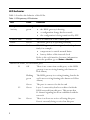
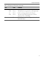
Codian ISDN Gateway
MSE 8321
Getting started
Codian ISDN GW
MSE 8321
Getting started
Copyright © Codian 2008. All rights reserved. This Getting Started Guide may not
be copied, photocopied, translated, reproduced, or converted into any electronic or
machine-readable form in whole or in part without prior written approval of Codian
Limited.
Codian Limited reserves the right to revise this documentation and to make changes
in content from time to time without obligation on the part of Codian Limited to
provide notification of such revision or change.
Codian Limited provides this documentation without warranty, term, or condition
of any kind, either implied or expressed, including, but not limited to, the implied
warranties, terms or conditions of merchantability, satisfactory quality, and fitness
for a particular purpose. Codian Limited may make improvements or changes to the
product(s) and/or the program(s) described in this documentation at any time.
All other product and company names herein may be trademarks of their respective
owners.
61-0020-02 rev 01
TANDBERG
Philip Pedersens vei 20
1366 Lysaker
Norway
Telephone: +47 67 125 125
Telefax: +47 67 125 234
Video: +47 67 117 777
E-mail: [email protected]
Table of contents
General information ................................................................................................................ 1
About the ISDN gateway .......................................................................................... 1
Port and LED location ................................................................................................ 1
LED behavior ................................................................................................................ 2
Installing the ISDN gateway .................................................................................................. 4
Install the ISDN gateway into the MSE 8000 chassis ...................................... 4
Connecting the ISDN gateway ............................................................................................ 6
Your ISDN connection ............................................................................................... 6
Step one: Connect to Ethernet Port A ................................................................. 6
Step two: Connect to the ISDN ports ................................................................... 6
Initial configuration ................................................................................................................. 7
Step one: Configure Ethernet Port A settings .................................................. 7
Step two: Assign an IP address to the ISDN gateway .................................... 7
Configuring the ISDN gateway ............................................................................................ 8
Step one: Log in to the ISDN gateway ................................................................. 8
Step two: Set up the ISDN interfaces ................................................................... 8
Step three: Configure an H.323 gatekeeper ...................................................... 9
Step four: Configure the dial plan ......................................................................... 9
Troubleshooting and technical support information ...............................................11
Calls fail to complete ...............................................................................................11
Using the event log to help solve a problem ..................................................11
Getting more help ....................................................................................................12
Pin outs .......................................................................................................................................13
General information
General information
About the ISDN gateway
The ISDN gateway is a high performance video gateway which enables ISDN network
connectivity for the Codian IP-based video infrastructure products as well as
IP-based endpoints.
Port and LED location
Figure 1 shows the position of ports on the ISDN gateway.
Figure 1: ISDN gateway front panel
Compact Flash
Activity LED
Console Port
Console Link LED
Status LED
Alarm LED
ISDN Ports
ISDN Port Status LEDs
Ethernet Ports
Ethernet Port Status LEDs
Power LED
1
LED behavior
Table 1 describes the behavior of the LEDs.
Table 1: ISDN gateway LED behavior
LED
Color
Indicates
Compact Flash
Activity
Flashing
green
Console Link
Green
A PC is connected to the console port
Status
Green
The ISDN gateway is operating normally
Alarm
Red
The ISDN gateway is booting or has developed a
fault, for example:
temperature is outside normal limits
battery failure of the internal clock
Refer to the web interface for more information
about the problem (go to Status > Health)
One of:
the ISDN gateway is booting
a configuration change has been made
the configuration is being transferred by FTP
ISDN Port Status, for each ISDN port:
L1
2
Off
There is no connection on this port, or the ISDN
gateway is not receiving framing (also known as
Red Alarm)
Flashing
green
The ISDN gateway is receiving framing, but the far
end is not receiving framing (also known as Yellow
Alarm)
Green
The port is connected to the far end
L2
Green
Layer 2 connectivity has been achieved with the
ISDN network from this port. This means that
D-channel signaling has been established with the
network
Act
Green
There is at least one active call using this port.
Data is currently being received on this port
General information
Table 1: ISDN gateway LED behavior (continued)
LED
Color
Indicates
Ethernet Port Status, for each Ethernet port:
Power
FDX
Green
The link has been negotiated as a full-duplex link
Act
Green
Packets are being transmitted on this port
Link
Green
The speed of the link from this port, which is
either 10, 100, or 1000 Mbps
Blue
The ISDN gateway is receiving power from the
MSE 8000 chassis
3
Installing the ISDN gateway
IMPORTANT: Before installing the ISDN gateway into the MSE 8000, and
connecting the power supply, you must read the safety information at
http://www.codian.com/safety.htm
!
Although blades are hot-swappable parts, you must only remove one
blade at any time. Remove the power from the MSE 8000, if you need to
remove more than one blade at a time.
!
Before hot-swapping a blade, shut down the blade using the web
interface. Do not shut down a blade during a software upgrade or if the
blade is processing.
For information about powering the MSE 8000, refer to the Getting Started Guide
that accompanied the chassis.
Install the ISDN gateway into the MSE 8000 chassis
1
2
3
4
4
!
You must install either a blade or a blanking blade in each of the ten
positions in the chassis.
!
The Supervisor blade must be installed into slot 1 of the MSE 8000
chassis.
Remove the blade or blanking blade from the slot into which you are going to
install the ISDN gateway:
i Using a No.1 Phillips screwdriver, loosen the screws in the retaining latches
with an anti-clockwise quarter turn.
ii Open both retaining latches on the front of the blade or blanking blade.
When open, a retaining latch is at a 90° angle perpendicular to the front of
the blade.
iii Slide out the blade or blanking blade.
Open both retaining latches on the front of the ISDN gateway. When open, a
retaining latch is at a 90° angle perpendicular to the front of the blade.
Slide the ISDN gateway into the blade slot (as shown in Figure 2) until it stops.
Simultaneously close both retaining latches on the blade (thereby engaging the
connectors at the rear of the blade) to secure in the chassis as shown in Figure 3.
Installing the ISDN gateway
5
Using a No.1 Phillips screwdriver, tighten the screws in the retaining latches
with a clockwise quarter turn.
Figure 2: Inserting a blade into the chassis
Figure 3: Closing the retaining latches on the front of a blade
5
Connecting the ISDN gateway
Your ISDN connection
To reduce the risk of fire, use only 26 AWG or larger telecommunication
line cord.
Outside North America
Check with your network provider to ensure that your incoming ISDN PRI line is
terminated in an NTU/CSU (Network Termination Unit/ Channel Service Unit). If
it is not, then seek their advice regarding the provisioning of such a device. Do not
connect the ISDN gateway directly to an external ISDN line.
Within North America
If your network provider has not terminated all of your incoming ISDN PRI lines
with an NTU/CSU, Codian recommends that you install a suitably approved CSU to
protect the ISDN gateway from damage by surges on your ISDN PRI lines.
Step one: Connect to Ethernet Port A
Connect an Ethernet cable from Ethernet Port A to an Ethernet switch (rather than a
hub, to minimize interference from other devices on the network). The Ethernet
port is a 10/100/1000 Mbps auto-sensing connection.
i
Only connect to Ethernet Port A. Ethernet Port B is reserved for future
expansion; do not connect anything to Ethernet Port B.
Step two: Connect to the ISDN ports
The ISDN gateway uses a standard RJ48C ISDN interface for each PRI port.Use a
single straight-through STP patch cable to connect each PRI port on the ISDN
gateway to your ISDN connection.
For information about the behavior of the ISDN port LEDs, refer to Table 1, ISDN
gateway LED behavior, on page 2.
6
Initial configuration
Initial configuration
Step one: Configure Ethernet Port A settings
The default setting for the ISDN gateway Ethernet ports is auto-sensing mode. If the
switch ports to which you connect the ISDN gateway are not also set to auto-sensing
mode, then you need to configure the ISDN gateway Ethernet ports to use the same
speed and duplex mode.
i
Only connect to Ethernet Port A. Ethernet Port B is reserved for future
expansion; do not connect anything to Ethernet Port B.
i
Both ends of the Ethernet connection must be configured in the same
way. For example, either configure both ends of the link to be autosensing or configure both ends to operate at the same speed and duplex.
i
To establish a 1000Mbps connection, both ends of the link must be
configured as auto-sensing.
To configure Ethernet Port A, log in to the Supervisor’s web interface and go to
Hardware > Blades. For more information about configuring the port, refer to the
online help accessible from the Supervisor’s web interface.
Step two: Assign an IP address to the ISDN gateway
You can use the Supervisor’s web interface to configure the IP addresses of all blades
installed in the MSE 8000. Note that all blades are supplied with DHCP enabled. You
can either keep this setting or assign static IP addresses to a blade from the
Supervisor’s web interface. To view or configure the IP address of the ISDN gateway,
log in to the Supervisor and go to Hardware > Blades. To access the web interface of
the ISDN gateway, go to Hardware > Blades and click the IP address of that blade.
7
Configuring the ISDN gateway
Step one: Log in to the ISDN gateway
All administration of the ISDN gateway is performed via the web interface.
1 To log in to the Log in to the Supervisor’s web interface.
2 Go to Hardware > Blades and click the IP address of the ISDN gateway.
3 Click Click here to log in, and then click Change log in and enter the user
name admin with no password.
i
Codian recommends that you change the admin account to use a
password as soon as possible. To do that, go to Users, click the admin
link, and provide the required user information.
Step two: Set up the ISDN interfaces
1
2
3
4
5
6
7
8
9
8
In the web interface, go to Settings > ISDN.
Select the ISDN interface type to match that of your installation; E1 is typically
used in the UK and mainland Europe, T1 (USA and Canada) in North America,
and T1(Japan) in Japan.
Complete the other settings as required by your network, referring to the online
help for further information.
Click Apply changes to save any changes you have made to the configuration.
Restart the ISDN gateway (this is only necessary if you changed the ISDN
configuration). To do this:
i Go to Settings > Shutdown, and click Shut down ISDN GW.
ii Confirm that you want to shut down the ISDN gateway.
iii Click Restart ISDN GW.
When the ISDN gateway has restarted, log in to the web interface again, and go
to Settings > ISDN ports.
Complete the settings for ISDN Port 1 as required by your network, referring to
the online help for further information. Note that all ISDN ports on the ISDN
gateway are enabled by default.
Click Apply changes to save your configuration changes to the ISDN port.
If required, configure another ISDN port by selecting the port number from the
numbered links at the top right of the ISDN port configuration page.
Configuring the ISDN gateway
Step three: Configure an H.323 gatekeeper
If you have H.323 endpoints, using an H.323 gatekeeper can make it easier for callers
to make their call. You can configure the ISDN gateway to use an external gatekeeper
or its own built-in gatekeeper.
To configure the use of an H.323 gatekeeper, go to Settings > Gatekeeper. Typically
you may want to add a Dial plan prefix for voice calls (for example 9) and another for
video calls (for example 8).
For more information refer to the online help topic: “Configuring gatekeeper
settings”.
Step four: Configure the dial plan
The default behavior of the ISDN gateway is to reject all calls. You must configure a
dial plan to allow permitted calls to be placed.
Below are some simple configurations for dial plan rules.
IP to ISDN dial plan setup
This example allows IP codecs to dial (via a gatekeeper) the ‘phone number of the
destination endpoint, using a prefix of 9 for audio calls and 8 for video calls. It
assumes that you require both video and voice calls to be made from your IP network
to ISDN and that you have set up dial plan prefixes 8 and 9 on the ISDN gateway’s
Settings > Gatekeeper page.
1
2
3
4
5
6
In the web interface, go to Dial plan > IP to ISDN and click Add rule.
For Condition, select Called number matches and enter the correct match for
example 9(D*).
For Action, select Call this number and enter $1.
For Call type, select Telephone.
Leave the other values unchanged. Click Add rule to add the rule to the dial
plan.
Repeat steps 1 to 5 to create a second dial plan to accept and forward the video
calls with the correct format in Called number matches, for example 8(D*)
and for Call type, select Video.
9
ISDN to IP dial plan setup
Options 1 and 2 will automatically handle both voice and video calls.
Option 1 - This example assumes that you have a PRI line that has 100 numbers (00
to 99) associated with it and that all your endpoints are registered to a gatekeeper
with registrations in the range 5900 - 5999.
1
2
3
4
5
Go to Dial plan > ISDN to IP, and click Add rule.
For Condition, select Called number matches and enter the correct match for
example D*(DD), which will match the last 2 digits of the dialed number. To
match the last 3 digits, use D*(DDD).
For Action, select Call this number and enter 59$1.
For Call type, select Video.
Leave the other values unchanged. Click Add rule to add the rule to the dial
plan.
Option 2 - This example assumes that you have a PRI line which has 1 number
associated with it but you require access to multiple endpoints on the IP side. When
you dial you will be greeted by the ISDN gateway's auto attendant and using TCS-4
or DTMF you can dial the extension of the IP endpoint, if known.
1
2
3
4
5
Go to Dial plan > ISDN to IP, and click Add rule.
For Condition, select Match any called number.
For Action, select Enter the auto attendant + TCS-4.
For Call type, select Video.
Leave the other values unchanged. Click Add rule to add the rule to the dial
plan.
There are a number of different ways in which you can use the dial plan. For
example, you can use the dial plan to link specific bandwidths to certain prefixes,
thereby enabling users to use the correct bandwidth for an IP to ISDN call. You can
also use the dial plan to enable the ISDN gateway to join incoming ISDN calls to the
correct conference on an MCU. These dial plan configurations — and the dial plan
rule syntax — are explained in greater detail and with supporting examples in the
online help accessible from the web interface.
10
Troubleshooting and technical support information
Troubleshooting and technical support information
Refer to this section if you are experiencing difficulties with the ISDN gateway.
Ensure that you have followed the instructions in this guide when installing and
configuring the ISDN gateway.
Calls fail to complete
If outgoing calls fail to complete, check that you have configured the ISDN gateway
and all other equipment correctly, paying particular attention to the number you are
trying to call. Remember that endpoints may be busy when you call them.
Using the event log to help solve a problem
Unless you are experiencing a problem, all event logging sources should be set to the
default, which is Errors, warnings and information. For more information about
configuring the event log, refer to the online help accessible from the web interface.
You can use the event log to produce debugging information to assist technical
support in solving your problem. However, we recommend that you only alter the
setting of the event log under the guidance of technical support representatives. In
particular, it is not recommended that you indiscriminately turn on event logging
sources.
11
Getting more help
If the documentation does not answer your question or you have a problem with one
of our products:
1
2
3
12
Refer to the Technical FAQ and Troubleshooter sections of the web site. We
keep both sections up to date with the latest information from our technical
support team regarding the resolution of customer issues.
Contact your reseller. Our resellers have a wealth of experience with our
products and this is sometimes a quick way of solving a problem.
If your query remains unsolved, there is a web form in the Support area of the
web site that you can complete. Ensure that you provide all the details requested
by the form to assist the technical support team in resolving your problem:
the serial number and product model number (for example: MSE 8321) of
the MSE blade
the software build number (to find this, in the web interface, go to Status >
General)
where you purchased the MSE blade
your contact email address or telephone number
Pin outs
Pin outs
The pin numbering for the PRI ports on the ISDN gateway is shown in Figure 4. The
pin assignments for the PRI ports are shown in Table 2:
Table 2: Pin assignments for PRI ports
Pin number
Signal
1
Receive -
2
Receive +
3
Not connected
4
Transmit -
5
Transmit +
6
Not connected
7
Not connected
8
Not connected
Figure 4: Pin numbering for PRI ports
8 7 6 5 4 3 2 1
13
61-0020-02