1
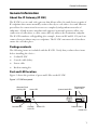
Codian IP Gateway
IP GW 3500 Series
Getting started
Codian IP Gateway
IP GW 3500 Series
Getting started
Copyright © Codian 2008. All rights reserved. This Getting Started Guide may not
be copied, photocopied, translated, reproduced, or converted into any electronic or
machine-readable form in whole or in part without prior written approval of Codian
Limited.
Codian Limited reserves the right to revise this documentation and to make changes
in content from time to time without obligation on the part of Codian Limited to
provide notification of such revision or change.
Codian Limited provides this documentation without warranty, term, or condition
of any kind, either implied or expressed, including, but not limited to, the implied
warranties, terms or conditions of merchantability, satisfactory quality, and fitness
for a particular purpose. Codian Limited may make improvements or changes to the
product(s) and/or the program(s) described in this documentation at any time.
All other product and company names herein may be trademarks of their respective
owners.
61-0014-03 rev 01
TANDBERG
Philip Pedersens vei 20
1366 Lysaker
Norway
Telephone: +47 67 125 125
Telefax: +47 67 125 234
Video: +47 67 117 777
E-mail: [email protected]
www.tandberg.com
Table of contents
General information ................................................................................................................ 1
About the IP Gateway (IP GW) ................................................................................ 1
Package contents ........................................................................................................ 1
Port and LED location ................................................................................................ 1
LED behavior ................................................................................................................ 2
Connecting the IP GW ............................................................................................................. 4
Before you start ........................................................................................................... 4
Step one: Connect power ........................................................................................ 4
Step two: Connect to Ethernet Ports A and B ................................................... 4
Initial configuration ................................................................................................................. 5
Step one: Connect to the console port ............................................................... 5
Step two: Configure Ethernet Port A ................................................................... 5
Step three: Assign an IP address to Port A ......................................................... 6
Step four: Discover the IP address of the IP GW .............................................. 6
Configuring the IP GW ............................................................................................................ 7
Step one: Log in to the IP GW ................................................................................. 7
Step two: Configure Ethernet Port B settings (optional) .............................. 7
Step three: Configure the default gateway and routes (optional) ............ 8
Step four: Configure an H.323 gatekeeper or SIP registrar (optional) ..... 8
Step five: Configure the auto attendant menus (optional) ......................... 9
Step six: Configure an operator (optional) ........................................................ 9
Step seven: Add endpoints and call groups (optional) ...............................10
Step eight: Configure the dial plan ....................................................................10
Checking for updates ............................................................................................................11
Troubleshooting and technical support information ...............................................12
Using the event log to help solve a problem ..................................................12
Getting more help ....................................................................................................12
Technical specifications .......................................................................................................13
Anti-static precautions .........................................................................................................13
General information
General information
About the IP Gateway (IP GW)
The IP GW is a voice and video gateway that allows calls to be made between pairs of
IP endpoints that cannot normally connect directly to each other. A second Ethernet
port allows for connections between two completely independent networks of
endpoints. A built-in auto attendant and support for manual operators allow easy
connection of calls where a caller cannot directly address the destination endpoint.
The IP GW translates call signalling (for example, between SIP and H.323) and can
connect between almost any two endpoints. The IP GW can transcode all media to
ensure the call takes place.
Package contents
The following items are included with the IP GW. Verify that you have these items
before installing the device:
Codian IP GW
Console cable (blue)
Power cable
Rack mounting kit
Port and LED location
Figure 1 shows the position of ports and LEDs on the IP GW.
Figure 1: IP GW front panel
Compact Flash
Status LED
Activity LED
Console Port
Console
Link LED
Alarm LED
System Load LEDs
Ethernet Port
Status LEDs
Ethernet Ports
Power LED
1
LED behavior
Table 1 describes the behavior of the LEDs.
Table 1: IP GW LED behavior
LED
Color
Indicates
Compact Flash Activity
Flashing
green
One of:
the IP GW is booting
a configuration change has been made
the configuration is being transferred
by FTP
Console Link
Green
A PC is connected to the console port
Status
Green
The IP GW is operating normally
Alarm
Red
The IP GW is booting or has developed a
fault, for example:
temperature is outside normal limits
fan failure
battery failure of the internal clock
Refer to the web interface for more
information about the problem (go to
Status > Health)
System Load
2
Green
The IP GW is processing data. The LEDs
represent the media processing load of the
IP GW. The column numbered 1
represents audio load. The other columns
represent video DSP load. Media
processing load is also displayed in the web
interface: go to Status > General to see
the percentage load
General information
Table 1: IP GW LED behavior (continued)
LED
Color
Indicates
Ethernet Port Status, for each
Ethernet port:
Power
FDX
Green
The link has been negotiated as a fullduplex link
Act
Green
Packets are being transmitted on this port
Link
Green
The speed of the link from this port,
which is either 10, 100, or 1000 Mbps
Blue
The IP GW is receiving power
3
Connecting the IP GW
Before you start
IMPORTANT: Before installing the IP GW, you must read the safety
information at http://www.codian.com/safety.htm
Step one: Connect power
Connect the power connector on the rear of the unit to the power supply using the
supplied power cable. (There is no On/Off switch.)
Connecting power causes the Power LED to light blue and when the IP GW has
booted (which can take up to two minutes), the Status LED will light green.
Step two: Connect to Ethernet Ports A and B
Connect an Ethernet cable from Ethernet Port A to an Ethernet switch (rather than a
hub, to minimize interference from other devices on the network). The Ethernet
port is a 10/100/1000 Mbps auto-sensing connection.
Connect Port A to your local network and connect Port B to a second subnet or the
internet depending on your application of the IP GW.
!
4
Do not connect Ethernet Port A and Ethernet Port B to the same subnet.
Initial configuration
Initial configuration
Step one: Connect to the console port
1
2
3
4
Ensure power is connected to the IP GW and the Status LED is green.
Connect the console port of the IP GW to the serial port of your PC using the
blue RJ45 to DB9 cable supplied.
Use a serial terminal program, such as SecureCRT or HyperTerminal, to
connect to the IP GW. Set your terminal software to the following settings:
Baud rate:
38400
Data bits:
8
Parity:
none
Stop bits:
1
Flow control: none
Press Enter. The following command prompt appears on the terminal: IPGW:>
Step two: Configure Ethernet Port A
The default setting for the IP GW Ethernet ports is auto-sensing mode. If the switch
ports to which you connect the IP GW are not also set to auto-sensing mode, then
you need to configure the IP GW Ethernet ports to use the same speed and duplex
mode.
i
Both ends of the Ethernet connection must be configured in the same
way. For example, either configure both ends of the link to be autosensing or configure both ends to operate at the same speed and duplex.
i
To establish a 1000Mbps connection, both ends of the link must be
configured as auto-sensing.
To configure Ethernet Port A, enter the following for auto-sensing mode:
ethertype auto
or to configure a speed and duplex, use the following command:
ethertype <10|100> <half|full>
For example, to configure a full-duplex 100Mbps link, enter:
ethertype 100 full
To display the current configuration and status of the Ethernet ports, enter:
status
5
Step three: Assign an IP address to Port A
The default setting for the IP GW is to use DHCP to obtain an IP address for Port A.
You can assign a static IP address if you prefer or if a DHCP server is not available.
If you want the IP address of the IP GW to be assigned by your DHCP server, omit
this step.
To assign a static IP address, use the following command:
static <IP address> <netmask> <default gateway address>
<DNS server address>
i
If you do not have a DNS server, use 0.0.0.0 as the DNS server IP
address.
For example, to assign an address of 192.168.1.2 where the default gateway is at
192.168.1.1, and there is no DNS server, enter:
static 192.168.1.2 255.255.255.0 192.168.1.1 0.0.0.0
To return to using DHCP after setting a static address, use the following
command:
dhcp
Step four: Discover the IP address of the IP GW
1
2
6
To display the current status of the IP address, enter: status
If you have DHCP enabled on your network and you are allowing the IP GW to
acquire its address using DHCP, the IP address that has been acquired by
Ethernet Port A will be shown; if you have assigned a static IP address, that is the
address that will be shown.
Make a note of the IP address. You will use this to access the web interface of the
unit.
Configuring the IP GW
Configuring the IP GW
Step one: Log in to the IP GW
All administration of the IP GW is performed through the web interface.
To log in to the web interface of the IP GW:
1
2
Use your browser to navigate to the IP address of the IP GW (to discover the IP
address, refer to the previous section).
Click Click here to log in, and then click Change log in and enter the user name
admin with no password.
i
Codian recommends that you change the admin account to use a
password as soon as possible. To do that, go to Users, click the admin
link, and provide the required user information.
Step two: Configure Ethernet Port B settings (optional)
Port B is configured through the web interface.
The default setting for the IP GW Ethernet ports is auto-sensing mode. If the switch
ports to which you connect the IP GW are not also set to auto-sensing mode, then
you need to configure the IP GW Ethernet ports to use the same speed and duplex
mode.
1
2
3
4
i
Both ends of the Ethernet connection must be configured in the same
way. For example, either configure both ends of the link to be autosensing or configure both ends to operate at the same speed and duplex.
i
To establish a 1000Mbps connection, both ends of the link must be
configured as auto-sensing.
To configure Ethernet Port B, go to Network > Port B.
Enter the IP address, subnet mask, default gateway and DNS name server for the
port.
Enter a secondary name server and domain name if required.
Click Update IP configuration.
7
Step three: Configure the default gateway and routes
(optional)
If the networks to which you connect contain more than one subnet, you might need
to change the default gateway preference on the IP GW (default setting is Port A).
You might also need to add routes to the configuration of the IP GW to indicate
which interface will be used for certain IP addresses.
To configure the default gateway and route information:
Log in to the IP GW and go to Network > Routes.
For more information about route configuration, refer to the online help topic:
“Configuring IP routes settings”.
Step four: Configure an H.323 gatekeeper or SIP registrar
(optional)
If you have H.323 endpoints, using an H.323 gatekeeper can make it easier for callers
to make their call. You can configure the IP GW to use an external gatekeeper or its
own built-in gatekeeper.
If you have SIP endpoints, using a SIP registrar can make it easier for callers to make
their call.
To configure the use of an H.323 gatekeeper, go to Settings > H.323
To configure the use of a SIP registrar, go to Settings > SIP
For more information refer to the online help topics: “Configuring H.323 settings”
and “Configuring SIP settings”.
8
Configuring the IP GW
Step five: Configure the auto attendant menus (optional)
Depending on the proposed configuration of your dial plan, and the settings for failed
calls, callers can be connected to an auto attendant menu. The IP GW provides a
highly flexible menu-creation feature. This enables you to create a menu (or a multilayered menu structure) to provide end users with the options they require when
they connect to the IP GW. Menus can provide end users with access to videos,
operators, address books, dial-it-yourself functions, and audio files.
To configure auto attendant menus, go to Menus > Menu builder
For more information, refer to the online help topics: “Creating auto attendant
menus”, “Configuring failed call settings”, and “Understanding the dial plan”.
Step six: Configure an operator (optional)
An operator is a person who can put calls through on the IP GW. You can use the dial
plan to automatically connect calls to an operator, you can have the operator as an
option on an auto attendant menu, and connection to an operator is an option for
failed calls. An operator connects the calls one by one as calls reach the top of the
operator's call queue which is displayed on the operator’s web page and is
automatically refreshed.
An operator can put calls through to configured endpoints and call groups that have
been given names in the system, or to any other endpoint by manually entering the
IP address or E.164 number of the endpoint.
You can configure one or more operators.
To configure an operator, go to Settings > Operator
For more information, refer to the online help topics: “Understanding operator
features” and “Configuring operator settings”.
9
Step seven: Add endpoints and call groups (optional)
You can pre-configure a list of endpoints on the IP GW. For these endpoints, an
operator or caller can simply choose the endpoint's name from an onscreen address
book, rather than having to type in the endpoint's address when a caller wants to be
connected to that endpoint.
You can group configured endpoints into call groups. When a call group receives a
call, all endpoints in the call group will ring and the first to be answered will take the
call. Call groups can be useful in organizations that have, for example, sales or
support teams where anyone from the team can take a call. An operator or caller can
choose a call group to which to connect an incoming call from the address book.
When you configure endpoints and call groups, you can select whether or not that
endpoint or call group will be shown in the address book. Callers can connect to that
endpoint, without the caller having to know its address.
To configure endpoints and call groups, go to Endpoints
For more information, refer to the online help topics: “Configuring endpoints” and
“Configuring call groups”.
Step eight: Configure the dial plan
The default behavior of the IP GW is to reject all calls. You must configure a dial plan
to allow permitted calls to be placed. The dial plan is in two parts: a dial plan for calls
arriving on Port A and a dial plan for calls arriving on Port B.
There are a number of different ways in which you can use the dial plan. For
example, you can configure a particular prefix that will forward calls to the operator
and another to connect callers to the auto attendant.
To configure the dial plan, go to Dial plan
Dial plan configuration (with supporting examples) is explained in greater detail in
the online help; refer to the topics: “Understanding the dial plan”, “Adding and
updating dial plan rules”, “Example dial plan rules”, “Dial plan syntax”, and
“Displaying and testing the dial plan”.
10
Checking for updates
Checking for updates
It is a good idea to regularly check for updates to the main IP GW software image.
This section describes how to upgrade the IP GW using the web interface. Note that
you can also upgrade the IP GW using FTP; this can be more reliable if you are
upgrading the device remotely. Upgrading your device via FTP is described in the
release notes that are available alongside the software images in the support section of
the Codian web site (www.codian.com).
To check for, and download, updates:
1
2
3
4
Log in to the IP GW web interface and go to Status > General.
Make a note of the software version that is currently installed.
Go to the support section of www.codian.com and check if a more recent
release is available for the IP GW.
If a more recent release is available, download it and save it locally.
To upgrade the IP GW:
1
2
3
4
5
Unzip the software release file that you downloaded.
In the IP GW web interface, go to Settings > Upgrade.
In the Main software image section, click Browse and locate the unzipped file.
Click Upload software image. The browser begins uploading the file to the IP
GW, and a new browser window opens to indicate the progress of the upload.
When finished, the browser window refreshes and indicates that the software
upgrade is complete and a Shut down IP GW button is displayed.
Click Shut down IP GW, confirm shut down, and restart the IP GW.
i
Note that shutting down the IP GW will disconnect all callers.
11
Troubleshooting and technical support information
Using the event log to help solve a problem
Unless you are experiencing a problem, all event logging sources should be set to the
default, which is Errors, warnings and information. For more information about
configuring the event log, refer to the online help accessible from the web interface.
You can use the event log to produce debugging information to assist technical
support in solving your problem. However, we recommend that you only alter the
setting of the event log under the guidance of technical support. In particular, you
should not turn on event logging sources without good cause or advice from
technical support.
!
Increasing logging can degrade system performance.
Getting more help
If the documentation does not answer your question or you have a problem with one
of our products:
1
2
3
12
Refer to the Technical FAQ section of the web site. We keep the Technical FAQ
section up to date with the latest information from our technical support team
regarding the resolution of customer issues.
Contact your reseller. Our resellers have a wealth of experience with our
products and this is often a quick way of solving a problem.
If your query remains unsolved, there is a web form in the Support area of the
web site that you can complete. Ensure that you provide all the details requested
by the form to assist the technical support team in resolving your problem:
the serial number and product model number (for example: IP GW 3510)
of the unit
the software build number (to find this, in the web interface, go to Status >
General)
where you purchased the unit
your contact email address or telephone number
Technical specifications
Technical specifications
Power requirements
Table 2: IP GW ratings
Rating
Value
Nominal voltage
115V to 230V 50/60 Hz
Current rating
2A Maximum
Supply voltage range
100 to 240V 50/60 Hz
Over-current protection
Ensure the supply to this unit is protected by a branch circuit protector rated by a
maximum of 20A.
!
Caution — over-current devices must meet applicable national and local
electrical safety codes and be approved for the intended application.
Operating environment
The IP GW must only be used within the following environmental conditions:
Table 3: Operating environment
Environment
Temperature
Humidity
Operating environment
0°C to 35°C
10% to 95%
(non-condensing)
Non-operating environment
-10°C to 60°C
10% to 95%
(non-condensing)
Optimum operating environment
21°C to 23°C
45% to 50%
(non condensing)
Anti-static precautions
When servicing or removing components or connections, first attach an anti-static
wrist strap to an appropriate earth point.
13
61-0014-03