1
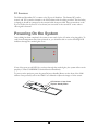
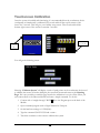
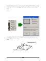
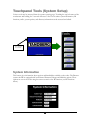
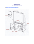
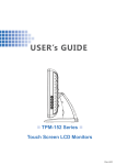
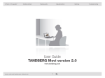
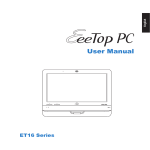
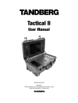
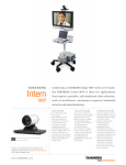
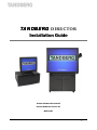
TANDBERG DIRECTOR
Installation Guide
Codec Software Version B5
Control Software Version V1
D501xx-01
-i-
Trademarks and copyright
COPYRIGHT © 2002,
TANDBERG
1860 Michael Faraday Drive
Reston, Virginia, USA 20190
Tel: 703-709-4281, Fax: 703-709-4231
All rights reserved. This document contains information that is proprietary to TANDBERG. No part of this
publication may be reproduced, stored in a retrieval system, or transmitted, in any form, or by any means,
electronic, mechanical, photocopying, or otherwise, without the prior written permission of TANDBERG.
Nationally and internationally recognized trademarks and tradenames are property of their respective holders
and are hereby acknowledged.
Disclaimer
The information in this document is furnished for informational purposes only, is subject to change without
prior notice, and should not be construed as a commitment by TANDBERG.
The information in this document is believed to be accurate and reliable, however TANDBERG assumes no
responsibility or liability for any errors or inaccuracies that may appear in this document, nor for any
infringements of patents or other rights of third parties resulting from its use. No license is granted under any
patents or patent rights of TANDBERG.
Technical Support, call one of the following service centers:
USA
Canada
Europe & Asia Pacific
TANDBERG Inc
1860 Michael Faraday Drive
Reston, Virginia 20190
Tel: 703 709 4281
Toll free: 800 889 7440
Fax: 703 709 4231
Video: 703 437 6991
Email: helpdesk @ tandbergusa.com
TANDBERG Canada Inc.
6505 Trans-Canada Hwy.
Montreal, Quebec
H4T 1S3
Tel: 514 748 5224
Toll free: 800 729 6990
Fax: 514 748 5760
Video: 514 744 5514
TANDBERG ASA
Philip Pedersens vei 22
1366 Lysaker, Norway
Tel: +47 67 125 125
Fax: +47 67 125 234
Video: +47 67 177 777
Mailing Address:
TANDBERG ASA
P.O. Box 92
1325 Lysaker, Norway
- ii -
Table of Contents
TRADEMARKS AND COPYRIGHT................................................................II
INTRODUCTION................................................................................................. 5
PRECAUTIONS.................................................................................................... 6
UNPACKING ........................................................................................................ 6
Smartboard Specific ......................................................................................................6
ROOM CONFIGURATION AND SETUP ........................................................ 8
DIRECTOR MODULE INSTALLATION......................................................... 9
COMPONENT IDENTIFICATION ................................................................... 9
BASIC SYSTEM CONNECTIONS .................................................................. 11
CABLING ............................................................................................................ 12
ISDN BRI.....................................................................................................................12
ISDN PRI/T1 ...............................................................................................................12
LAN .............................................................................................................................12
DEVICE CONNECTIONS ................................................................................ 12
Microphone .................................................................................................................12
Touchpanel ..................................................................................................................12
Main Camera...............................................................................................................13
Aux Camera.................................................................................................................13
Document Camera.......................................................................................................13
VCR/DVD Player ........................................................................................................13
PC Sources ..................................................................................................................14
POWERING ON THE SYSTEM ...................................................................... 14
TOUCHSCREEN CALIBRATION .............................................................................. 15
TOUCHPANEL TOOLS (SYSTEM SETUP).................................................. 17
SYSTEM INFORMATION ........................................................................................ 17
- iii -
IR FUNCTIONS ..................................................................................................... 18
AUDIO ................................................................................................................. 18
SYSTEM OPTIONS ................................................................................................ 19
EDIT DIRECTORY ................................................................................................. 19
UPDATING THE DIRECTORY ................................................................................. 19
CODEC CONFIGURATION ............................................................................ 19
ESTABLISHING COMMUNICATIONS ...................................................................... 20
APPENDIX 1: AUDIOSCIENCE MICROPHONE ........................................ 22
AUDIOSCIENCE MICROPHONE PARTS LISTING .................................................... 22
TOOLS REQUIRED FOR ASSEMBLY AND INSTALLATION ....................................... 22
INSTALLATION CONSIDERATIONS ........................................................................ 23
SELECTING A MOUNTING LOCATION ................................................................... 24
ASSEMBLY AND INSTALLATION INSTRUCTIONS ................................................... 25
-4-
Introduction
Welcome to the TANDBERG Director
An Integrated Multi-Media and Videoconferencing System that can be integrated into a
Smartboard touch-sensitive rear projection system. The core component of the Director, the
Director Module (Director Applications Module) is a 19” rack mountable unit that provides all the
necessary audio, video, and network and control connections for videoconferencing. The Intuitive
On-Screen Controls provide configuration of multiple simultaneous displays from a variety of
sources. Annotation over the PC Image is possible in variety of colors and can be viewed by both
the local and remote participants.
The Videoconferencing Functions include; speed dials, Multi-site operation, Duo Video and
Native Resolution support.
An Optional Color Touchpanel provides desktop control of the system.
Touchpanel
Director Module
5
Smartboard 3000i
Precautions
Never install telephone wiring during a lightning storm
Never install telephone jacks in wet locations unless the jack is specifically designed for wet
conditions.
Use caution when installing or modifying telephone lines
Never do any installation of cables without first unplugging the power cords of the applicable
equipment.
Unpacking
To unpack and install the Director System, it is recommended (at the very least) that you have the
following tools:
#2 Phillips
#2 Flathead
5/32 hex key
diagonal wire cutters
flathead “tweaker”
razor or knife
Robertson square head screwdriver
PC (with installed Crestron software, com port) for setup and diagnostics
Smartboard Software
The “entire system” consists of the following components:
TANDBERG Director Module (1box)
• External cable pack (1box)
Codec Accessories (WAVE Camera, additional mics, network cables)
AudioScience Mic (1box)
Touchpanel (optional, 1 box)
Smart 3000i (optional, 1 big box)
• Smart 3000i Camera Shelf
• Smart Room Control Module (RCM)
• Smart software
Customer supplied PC (optional)
Smartboard Specific
(please skip over this section if you did not purchase the 3000i Smartboard option)
6
To unpack the 3000i , cut the straps, remove the outer cardboard packaging, and lower the
plywood Director Modulep.
Remove the bolts securing the bottom of the 3000i to the pallet, and make sure the locking casters
are in the off position. You will need to rotate the orange braces a ¼ turn to remove them from
underneath the 3000i cabinet. Carefully roll the unit down the ramp provided, and remove the
shrink-wrap with a razor blade or sharp knife.
Inside the 3000i cabinet, you will find the projector, keyboard, and accessory packaging. The
projector will be installed, but will need to be adjusted to fit the image correctly on the screen.
Refer to the Smart 3000i User’s Manual for adjusting the projected image.
Cabling for the projector should be present and labeled. The wireless IR receiver for the keyboard
should be in place and ready to plug into the customer PC. The wireless keyboard must be
hooked up to the PC and mouse ports, and the batteries (included) must be installed in the
keyboard. In the accessory box you will find the Smartboard markers and eraser.
7
To install the Videoconferencing Camera Bracket, it is important to know the location of the
presenter in relation to the camera. Place the camera bracket on the opposite side of the display
from the presenter. There is one existing hex screw on the top, and two screws on the bottom of
the cabinet to be used for mounting the bracket. The shelf fits into the slots provided and secures
using the thumbscrew provided.
For additional information, diagrams, and instructions, refer to the following reference guides
provided by Smart:
Reference: 3000i Installation Guide
Reference: 3000i Videoconference Shelf Installation Guide
Reference: 3000i Room Control Module Installation Guide
Room Configuration and Setup
The Director Module has been designed to provide versatility for installation at any site. The
following sections describe the Director installation in a typical room setup. The two most
common configurations are described below. The first shows the Director Module installed in a
Smart 3000i cabinet and the second shows a typical setup with a Director Module and touchpanel.
8
Director Module Installation
The 5RU Director Module comes ready for installation into a standard 19” rack unit. Place the
Director Module in the rack and secure using the 4 screw holes provided. If installing the Director
Module into the 3000i cabinet, place into the rack with the plexiglass front of the Director Module
behind the magnetic latches . If there the Director Module does not settle behind those latches, it
may be necessary to loosen the latches with a Robertson head screwdriver.
Remove adhesive protection
Component Identification
1
2
3
4
5
6
PC VGA IN
AUX CTRL 1
AUX CTRL 3
DISPLAY VGA OUT
AUX CTRL 2
PROGRAM
TOUCHPANEL
TOUCHSCREEN
MOUSE
CRESNET
10
11
12
7
8
9
LAN
DIAGNOSTICS
1. TANDBERG 6000 Codec.
2. PC VGA IN - Personal Computer Video Input, supports VGA, SVGA, and XGA
resolution (15 pin female HD D-sub connector). See TANDBERG 6000 User’s Manual
for more information regarding codec I/O.
3. DISPLAY VGA OUT - System Display VGA out, XGA resolution (15 pin female HD
D-sub connector).
9
4. AUX CTRL 1 - Bi-directional RS232 (9600,N, 8,1) supports Visca Camera Control (9 pin
female D-sub connector).
5. AUX CTRL 2 - Bi-directional RS232 (9600,N, 8,1) supports Smart 3000i Room Control
Module (9 pin female D-sub connector).
6. AUX CTRL 3 - Bi-directional RS232 (9600,N, 8,1) used for PC com port with Smart
Software Package (9 pin female D-sub connector).
7. PROGRAM - Bi-directional RS232 (115200,N, 8,1) used for diagnostics and loading
software to Director Module. (Note: due to time/speed considerations, it is recommended
that touchscreen software be loaded through the LAN connection. Control software may
be loaded without considerable delay) (9 pin female D-sub connector).
8. LAN DIAGNOSTICS - Ethernet port used for upgrading and troubleshooting the
control system (RJ45 connector).
9. Fused 120VAC Input.
10. TOUCHPANEL – Supports Optional Touch sensitive panel (25pin female D-sub
connector).
11. TOUCHSCREEN/MOUSE – Supports Smart 3000i touch overlay or Microsoft
compatible mouse (9 pin female D-sub connector).
12. CRESNET – Port reserved for future expansion of Cresnet devices (15 pin male D-sub
connector).
10
Basic System Connections
The following Diagram shows the basic system connections required for proper operation. For
simplicity the Network connections are not shown in the diagram below.
CABLE SUPPLIED WITH MICROPHONE
MICROPHONE
T323-0036
SMART 3000i AUDIO IN
LABELLED AS COMPUTER 1 AUDIO
WAVE
CAMERA
T204-0144
THESE CONNECTORS ARE USED INTERNAL TO THIS MODULE
DIRECTOR APPLICATIONS MODULE
PC VGA IN
AUX CTRL 1
AUX CTRL 3
DISPLAY VGA OUT
AUX CTRL 2
PROGRAM
TOUCHPANEL
TOUCHSCREEN
MOUSE
CRESNET
LAN
DIAGNOSTICS
CABLE PART OF 3000i (LABELLED AS COMPUTER 1 SERIAL)
T201-0072
SMART 3000i
PROJECTOR
AND TOUCH SCREEN
RCM
ROOM CONTROL MODULE
S055-0300
NET/VIDEO
RGB
OPTIONAL
TOUCH PANEL
CABLE PART OF 3000i (LABELLED AS COMPUTER 1 VIDEO)
SMART X-Port 10
T112-0036
T201-0036
T308-0036
NOTES:
1 - CABLE PART OF 3000i
(LABELLED AS RGB 2 IN)
2 - CABLE SUPPLIED WITH X-PORT 10
CONNECTS TO X-PORT 20 INTERNAL TO 3000I
SEE NOTE 2
PROJECTOR
VIDEO
COMPUTER 1
VIDEO
PEN
TRAY
DATA
COMPUTER 1
SERIAL
COMPUTER 1
AUDIO
T112-0036
T201-0036
T324-0036
SPEAKER
SEE NOTE 1
COMPUTER 2
VIDEO
COMPUTER 2
SERIAL
POWER SUPPLY
COMPUTER 2
AUDIO
RGB OUT
SERIAL
AUD OUT
INTERNAL
COMPUTER 1
RGB OUT
SERIAL
AUD OUT
T237-0072
EXTERNAL
COMPUTER 2
T325-0072
REAR INTERFACE PANEL ON 3000i
11
CABLE LOOM WITH 3000i
Cabling
Cables for this system are connected at the rear interface panel of the Director Application Module
(Director Module), either directly to the Codec. Connect cables to the Director Module as
required. Coil up any excess lengths of cable.
Connect the network cables that are applicable to the site. Refer to the TANDBERG 6000 User
Manual for more information concerning IP settings and other network equipment that may be
required, such as network terminating units and CSUs.
For additional information regarding the external cabling of the Director system, please refer to
the Director External Cabling Diagram.
ISDN BRI
Connect each cable (labeled 1 to 4) to the ISDN BRI sockets on the Codec. Then connect the
other end of the loom to the appropriate wall sockets. If however, the wall sockets provide an
ISDN U-interface, the ISDN lines from the Codec must first be connected to the S/T interface of
network terminating units NT1 and NT384. Then connect the U interface of the network
terminating units to the wall sockets.
ISDN PRI/T1
Connect the PRI/T1 cable to the PRI/T1 socket labeled “1” on the Codec. Connect the other end
of the cable to a Channel Service Unit (CSU). Then connect the CSU to the site’s PRI/T1 line.
LAN
Connect the LAN cable from the LAN connector on the rear of the Codec to the site’s LAN
network connection.
It is recommended that both the codec and control system be provided with a LAN connection.
The system will function without this connection, but is recommended for both software upgrades
and remote diagnostics. For information regarding the network settings on the codec, refer to the
TANDBERG 6000 User’s Manual. The control system LAN information must be set locally.
Device Connections
Microphone
Connect the microphone cable to the XLR input of the 6000 codec. The default codec setting has
all microphone inputs enabled and the gain set to +3dB. Adjustments to the audio settings may be
done in the “Touchscreen Tools” (discussed later in this document), or with the remote control.
Touchpanel
If a touchpanel was sold with the system, attach the male DB25 pin end of the cable to the
Director Module, and connect the RJ modular ends to the touchpanel. Power for the touchpanel is
12
wired in the NET/Video connector. Place the touchpanel where it will be used such as a podium
or presenter’s desk.
Main Camera
The main camera source selection corresponds to the first s-video input (labeled “1”) on the
codec. This camera input is designed to be used with the controllable TANDBERG WAVE
camera or a controllable VISCA camera.
When using the WAVE camera, connect the DB15 end of the cable to the camera and the DB9
cable end to the Data Port 2 connector on the codec.
Aux Camera
The auxiliary camera source selection corresponds to the second s-video input (labeled “2”) on the
codec. This camera input can be a fixed room camera or can be a second controllable
TANDBERG WAVE camera (or second controllable VISCA camera). To control a second
camera, control signaling must be “daisy-chained” from the first camera. Additionally, the camera
must be powered locally and the video must be run separately back to the codec.
Document Camera
Connect the composite video output of the document camera to video input 3 (labeled DOC) of
the codec.
VCR/DVD Player
If a vcr/dvd player is used with the system, the cables are to be connected directly to the codec. It
is possible to record both near AND far audio, but only the local OR only the far side video.
For a playback vcr or dvd players:
1. Connect one end of a RCA male-to-male cable to audio input 6 (labeled VCR)on the
codec, the other end to the audio output of the vcr.
2. Connect one end of a RCA male-to-male cable to video input 6 (labeled VCR), and the
other end to the video output of the vcr.
For recording the FAR SIDE video on the vcr or other video device:
1. Connect one end of a RCA male-to-male cable to audio output 3 (labeled VCR) on the
codec, the other end to the audio input of the vcr.
2. Connect one end of a RCA male-to-male cable to video output (labeled SINGLE), and the
other end to the video input of the vcr.
For recording the NEAR SIDE video on the vcr or other video device:
1. Connect one end of a RCA male-to-male cable to audio output 3 (labeled VCR) on the
codec, the other end to the audio input of the vcr
2. Connect one end of a RCA male-to-male cable to video output (labeled DUAL), and the
other end to the video input of the vcr.
(Note: If the far end sends a native VGA encoded image in a videoconference call, the
image displayed from an s-video or composite output may be mis-sized and
unsuitable for recording purposes.)
13
PC Sources
The Main and Secondary PC’s connect to the X-port 10 Switcher. The Internal PC’s audio,
control, and VGA connects internal to the 3000i cabinet with the cables provided. The Secondary,
or laptop pc should be connected to the external cable loom provided. These connections to the
X-port 10 allow for the first PC to be shown, but can switch to the second PC source when a
video signal is detected.
Powering On the System
Once cabling has been completed, the system is now ready for the AC mains to be plugged in. To
verify that all components have been powered on, you should be able to see the following LED
indicators through the smoked glass cover.
If any of the green or red LED’s do not show through the smoked glass, the system will not work
properly. Contact TANDBERG Technical Service immediately.
To power on the projector, press the green Projector Standby Button on the front of the 3000i
cabinet. Once powered, refer to the 3000i User’s Manual to adjust the image to fit the screen.
LED Indicator of Lamp Status
Projector Standby Button
14
Touchscreen Calibration
Once the system is installed and functioning, it is recommended that the touchscreen device
(touchpanel or Smartboard) is calibrated. First touch and hold the top left corner of the
screen for 5 seconds. This will give you a hidden setup screen. Then touch and hold the
bottom right corner of the screen for another 5 seconds.
Press and hold
for 5 seconds
Press and
hold
You will get the following screen.
Selecting “Calabrate System” will display a series of push-points on the touchscreen device used
to calibrate the screens. After the third pint, the system will restart and return to the Opening
Page. If it is not possible to reach this page because the calibration is too far off the screen, you
can connect direct to the Director Module and enter a simple command. To do this:
1. Connect with a “straight through” RS232 cable to the Program port on the back of the
Module.
2. Open a terminal program such as HyperTerminal or Viewport.
3. Set the baud rate settings to 115200,N,8,1.
4. Type the command CALTOUCH and <enter>.
5. Touch the crosshairs on the screen to calibrate the system.
15
If the 3000i Smartboard system is used on conjunction with the Director Module, it will also
be necessary to calibrate the Smartboard software on the computer. To do this, select the PC
as your video source and use the “Orient” utility found in the Smart software’s Control
Panel.
You can also calibrate the PC software by pushing the Keyboard and Right mouse buttons at
the same time, found on the front of the 3000i. You should calibrate the control system
before calibrating the Smart software.
Keyboard Button
Right-Mouse Button
16
Touchpanel Tools (System Setup)
Various tools may be accessed from the systems opening page. Touching the top left corner of the
touchscreen and holding for 5 seconds will access a list of tools where system information, IR
functions, audio, system options, and directory information can be accessed and edited.
Press and hold
for 5 seconds
System Information
This button gives information about options and bandwidths available on the codec. The Director
systems should be equipped with both Natural Presenter Package and Multisite options. These
options are set on the codec using the remote control or the IR functions (see IR Functions
below).
17
IR Functions
Selecting the IR Functions button will display a both near and far end video outputs as well as all
the buttons found on the TANDBERG remote control.. You can use any of these buttons to
emulate button pushes on the remote.
Audio
Choosing thee Audio button will display the Audio inputs and outputs of the codec. Touching the
+ or – For each input will raise or lower the gain of each input. Inputs may also be
disabled/enabled by touching the icon in the middle of each respective input.
(Note: When in the normal presentation and videoconference pages and the VCR source is
selected, the system will automatically turn on and off Audio Input 6 corresponding to that video
input.)
18
System Options
The system options button allows for limited modification of setup of the codec. Modification of
these setting from the default values may affect the operation of the Director system. The main
item of note is the Camera Model setting. The system supports VISCA controlled cameras and can
therefore is selectable between the WAVE and VISCA controlled cameras. VISCA cameras would
use the Aux 1 Output on the Director Rear Interface Panel.
Edit Directory
To edit the system directory directly, follow the instructions detailed in the Director Module User’s
Guide.
Updating the Directory
If installing a codec with directory entries existing on it, or if any of the directories have be
modified through any other method than using the Edit Directory method discussed above (i.e.
Codec Data port, Web browser, Telnet, or TMS), you must edit the
Codec Configuration
The control system communicates with the codec through Data 1 at 9600 baud, No parity bit, 8
data bits, and 1 stop bit. The codec should be left in it’s default configuration with the following
exceptions. Using the remote control, or the IR functions in the Setup Page, the following settings
should be changed.
Input codec software option keys
All network and LAN information (SPIDS, IP Addresses, etc. )
Autoanswer On (or On + Mic off)
Dual Monitor On
19
Duo Video Mode “Manual”
System name
Microphone setting
For more information regarding the codec setup, refer to the TANDBERG 6000 User’s guide.
Establishing Communications
If there is a need to upgrade the controller or touchpanel software, it imperative that the system be
connected to a LAN to avoid extremely long download times. This section is included only to
illustrate the proper method of setting the IP address for an upgrade (To be performed by a
TANDBER Representative. PLEASE CONTACT TANDBERG TECHNICAL SERVICES
BEFORE ATTEMPTING THIS ACTION.
Connect the local PC’s com port “straight through” to the Program port of the Director Module,
and start the Crestron “Viewport” program. In the “Setup” menu, change the “Communication
Settings” to RS-232 and the Com port # for the PC being used. Under “Diagnostics”, choose
“Establish Communications (Find Rack) Alt-B”. This action will find the baud rate, etc. for
the connection, and will open the connection. To set the static IP address on the control system,
select “Functions”, “Set Control System IP Information”. Enter the new IP Address, Subnet
Mask, and Default Router information. Once set, you should be able to return to the “Setup”
menu and connect using the IP address of the control system.
20
Hitting the ENTER key a few times should give you a “ DVP4> “ prompt.
21
Appendix 1: AudioScience Microphone
AudioScience Microphone Parts Listing
Before proceeding, please ensure that the following list of parts was received with your new
AudioScience Microphone package. If any part is missing or damaged, contact your
TANDBERG Representative to arrange for a replacement.
Qty
1
1
4
2
4
4
2
1
6
6
10
1
1
1
1
Part Description
Present?
Acrylic Top Deflector Fitted With Microphone Assembly
Rear Deflector
Cable Suspension Assemblies
Safety Cable Assemblies
9/16” Ceiling Track Clips
15/16” Ceiling Track Clips
1/4 Universal Snap Hooks
47' Plenum Rated Microphone Cable Assembly
Nylon Washers
Shoulder Screws
White Cable Ties
20 Foot Length of "Bailing" Wire
Bottle of Brillianize Plastics Cleaner
Sofkloth Towel
Assembly and Installation Instructions
Tools Required for Assembly and Installation
•
•
•
•
•
Step ladder (To suit ceiling height)
#1 Phillips Screwdriver
Wire cutter
Knife or other tool to notch the ceiling tiles
Any tools required to snake cable through the wall (if desired)
22
Installation Considerations
1. The standard hardware included with the microphone is intended to be clipped to ceiling
tracks with the standard inverted “T” shaped cross-section, and with the horizontal part
of that “T” to be either 9/16” (14 mm) or 15/16” (24 mm) in width. Ceilings which are
not of this design need to have a secure anchoring installed in the ceiling to hang the
microphone.
2.
The standard cable included with the microphone is 47 feet (14 meters) long and plenum
rated to comply with fire code regulations. This allows the microphone to be mounted
up to about 30 “ceiling feet” (9 meters) away from the system. If the microphone is
mounted further away, additional cable needs to be ordered. This cable is available in
several standard lengths and can be ordered from your local TANDBERG
Representative.
3. The microphone assembly has a pickup range of about 14 feet (5 meters). This means
that all seating positions should be within this range of the microphone capsule. If there
are substantial numbers of desired seating positions outside this area, then additional
microphones may need to be installed.
4. The microphone cable should be routed from the microphone on the ceiling to the
system on the floor in an aesthetic manner, such as within a conduit or wall “punchout”.
5. The AudioScience microphone is currently limited for use on the TANDBERG
Educator and other approved systems. Other applications will be documented, as they
become available.
23
Selecting a Mounting Location
The mounting location of the AudioScience microphone can be determined through the
application of three principles:
1. All desirable seating positions should be within 14 feet (5 meters) of the microphone
capsule, with an unobstructed line of sight to the microphone capsule.
2. All undesirable noise sources should be blocked from reaching the microphone capsule
by one or both boundaries of the microphone.
3. The mounting holes of the microphone boundary must be directly under a ceiling track
to allow for mounting hardware. Additionally, to allow for easier changing of lighting
tubes or bulbs, the microphone should not be mounted where the microphone blocks
these items. If, due to acoustic concerns, a light fixture has to be “blocked” then string
the microphone cable in such a way as to allow for removal of the microphone when
light bulbs or tubes need to be changed.
30 Feet /
9 Meters
14 feet /
5 Meters
M
I
C
Typical Room Mounting Arrangement
24
Assembly and Installation Instructions
1. Read the “Installation Considerations” on page 23 and proceed after all considerations
have been understood and satisfied.
2. Read the guidelines for “Selecting a Mounting Location” on page 24 and select a
mounting location.
3. Determine if the ceiling tracks are 9/16” (14 mm) wide or 15/16” (24 mm) wide. Eight
ceiling track clips have been included. Four are for 9/16” ceiling tracks, and four are for
15/16” (24 mm) ceiling tracks. Discard the four that are not required.
4. Attach the ceiling clips to the ceiling grid. Attaching the ceiling clip requires a twisting
motion while applying upward pressure on the clip. Adjoining ceiling tiles may need to
be pushed up to fully attach the ceiling clip. Place the clips in positions to match the
location of the AudioScience microphone's mounting holes at each corner of the top
deflector.
5. Remove the protective paper from all surfaces of the top and rear deflectors.
6. Attach the rear deflector to the top deflector using the two cable suspension assemblies
at the outer mounting holes, and two of both the shoulder screws and Nylon washers.
Tighten the shoulder screws to be “finger-tight.” In the same manner, attach the two
remaining cable suspension assemblies to the opposite corner mounting holes of the top
deflector.
7. With the assistance of another person, attach the AudioScience microphone assembly to
the ceiling.
25
This is done by supporting the acrylic structure while the cable suspension assemblies are
threaded onto the ceiling clips.
8. Attach the two safety cables to the AudioScience microphone, and connect them to solid
anchoring points in the ceiling. Do Not attach the safety cables to electrical or other
wiring. (The ¼” universal snap hooks and the bailing wire may be used to achieve this.)
Allow enough slack to let the ceiling tiles slide into place, but not enough to allow the
microphone unit to hit anyone in the case of ceiling track failure.
9. Push back the ceiling tiles located directly above the microphone unit. Route the
microphone cable up from the hole in the top deflector, along one of the safety cables,
to the ceiling. Use the supplied cable ties to attach the microphone cable to the safety
cable.
10. Plug the 47’ microphone cable assembly into the XLR connector connected to the
microphone capsule. Route the cable across the ceiling and down a wall located near the
Videoconferencing system. If the cable is to be installed in a wall, a “fish tape” or
conduit may be necessary to get the cable from the ceiling to the floor.
11. Replace the ceiling tiles. Small notches may need to be cut in the ceiling tiles to allow for
the microphone cable and safety cables.
12. Using the Brillianize plastic cleaner, and the Sofkloth towel, wipe clean the plastic
surfaces of the AudioScience microphone. The microphone is now ready for use.
26