1
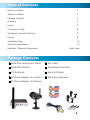
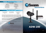
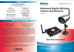
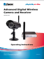
™
Advanced security made easy ™
Advanced Digital Wireless
Camera and Receiver
ADW-200
Operating Instructions
SW344-YDW
www.swannsecurity.com
MYDW290410E
1
Before You Begin
IMPORTANT
Before connecting power to the camera or receiver, ensure that the
antennas are properly attached to both devices. Operating the ADW-200
without the antennas in place can cause damage to the unit, and may void your
warranty.
FCC Verification:
NOTE: This equipment has been tested and found to comply with the limits for
Class B digital device, pursuant to part 15 of the FCC Rules. These limits are designed to provide reasonable protection against harmful interference in a residential installation. This equipment generates, uses and can radiate radio frequency
energy and, if not installed and used in accordance with the instructions, may
cause harmful interference to radio or television reception, which can be determined by turning the equipment off and on, the user is encouraged to try to correct the interference by one or more of the following measures:
· Reorient or relocate the receiving antenna
· Increase the separation between the equipment and the receiver
· Connect the equipment into an outlet on a circuit different from that to which
the receiver is connected
· Consult the dealer or an experienced radio/TV technician for help
IMPORTANT NOTE: Prohibition against eavesdropping
Except for the operations of law enforcement officers conducted under lawful
authority, no person shall use, either directly or indirectly, a device operated pursuant to the provisions of this Part for the purpose of overhearing or recording the
private conversations of others unless such use is authorized by all of the parties
engaging in the conversation.
WARNING: Modifications not approved by the party responsible for compliance
could void user’s authority to operate the equipment.
IMPORTANT SAFETY INSTRUCTIONS:
· Make sure product is fixed correctly and stable if fastened in place
· Do not operate if wires and terminals are exposed
2
Table of Contents
Before You Begin
2
Table of Contents
3
Package Contents
3
Overview
4
Layout
5
Connection Guide
6
Activating Channels & Pairing
8
Pairing
9
Troubleshooting
10
Technical Specifications
12
Helpdesk / Warranty Information
Rear Cover
Package Contents
ADW-200 Camera with Stand
A/V Cable
ADW-200 Receiver
Operating Instructions
2 X Antennas
Security Stickers
5V Power Adapter for Camera
Mounting Hardware
5V Power Adapter for Receiver
3
Overview
A Digital Wireless Monitoring Solution
The ADW-200 is a high quality yet cost effective digital wireless monitoring solution,
ideal for home or business use. Combining a robust and interference-free wireless
transmitter and receiver with a color camera with active infrared night vision, the
ADW-200 can be used as a complete monitoring solution or as a part of a larger
security solution, perhaps integrated with a DVR and alarm system.
Interference-free Digital Signal Transmission
Digital wireless technology is a huge step forward in wireless systems, which do
not suffer from interference in the same way as analog wireless systems.
This means that the ADW-200 system will deliver a picture from your cameras
which is free from distortion or noise. This is particularly useful in locations which
have a lot of other wireless systems operating.
Quick and Easy Setup
Get set up with the click of a couple of buttons. If you know how to plug in a DVD
player, you should have no problems getting the ADW-200 set up. However, this is
not to say that the ADW-200 has limited applications - you can connect it to a TV,
DVR or even directly to a PC.
Direct USB Connection to a PC
The ADW-200 receiver has a USB port which can easily be connected to a computer.
You can use the ADW-200 as a webcam, or use compatible recording software to
create a PC-based video recording setup.
Important Note - Range and Reception
The ADW-200 uses digital wireless technology which means that it doesn’t suffer
from interference in the same way as an analog wireless system. It is possible,
however, that a signal will “fade” before reaching the receiver. This typically
happens when the receiver is out of range of the camera, or there are significant
obstacles between the camera and receiver.
The range of the camera’s signal is approximately 20m/65ft, under typical conditions.
You should get a picture at this range if there are no significant obstacles between
camera and receiver, and there are no other wireless systems nearby operating on
a similar frequency. For maximum transmission range, the receiver should be in line
of sight of the camera.
A thick brick or concrete wall will dramatically reduce the range of the signal, often
by half or more. If you’re using the ADW-200 system in a cluttered environment
with other wireless devices nearby, you may find that the reliable range of
transmission is significantly reduced. In extreme cases, a wired system may be the
only practicable solution.
4
Layout
When Placing Multiple Cameras
Antenna
Light Sensor
Lens
When two or more digital wireless cameras are
placed too close together, the receiver can have
difficulty distinguishing between the two signals,
for much the same reason as it would be difficult
to listen to two people standing side by side and
both talking at the same volume.
Keep your cameras as far apart as possible –
ideally, at least 6 ~ 9 feet (approximately 2 ~ 3
meters).
Infrared LEDs
The result of two cameras too near one another
will be a reduction in quality of your picture, with
the possibility of a slight pause when changing
channels.
Stand
If you are experiencing these problems and simply cannot move cameras any father
apart, then try orienting the antennas away from one another. This will not have as
dramatic an effect as actually moving the camera, but often can provide somewhat
of an improvement.
Antenna
Channel Select Button
Channel Indicator LEDs
Placing the Receiver
The receiver should be placed in
a central location relative to your
cameras, to ensure the best possible
signal strength from each.
Power Input (DC 9V)
Audio/Video (AV) Output
USB Connection
Channel De/Activation &
Loop Mode Switches
Additionally, try to keep the receiver away from magnetic fields (particularly devices
such as microwaves or other wireless devices) or environments which would block
wireless signals (such as thick concrete or brick walls, or areas which have large
amounts of metal).
5
Connection Guide
1
3
2
Connecting the Camera
1. Attach the antenna to the rear of the camera.
2. Connect the supplied power adapter (5V) to the power input on the camera.
3. Plug the power adapter in to a wall socket.
Connecting the Receiver
4. Attach the antenna to the receiver.
5. Connect the supplied power adaptor to the power input on the rear of the
receiver.
6. Connect the supplied A/V cable to the A/V OUT port on the rear of the receiver
(the plug looks like a miniature headphone jack).
Connecting to a VCR / DVD Recorder
7. Connect the yellow VIDEO OUT plug to the VIDEO IN port (usually also yellow)
on your VCR/DVD recorder.
8. If you want to monitor/record audio, then plug the white AUDIO OUT plug
into the AUDIO IN port (also typically white) on the VCR/DVD recorder.
9. Connect the Video/Audio OUT of the VCR/DVD recorder to a TV as detailed
below.
Connecting to a DVR
10. Attach the yellow VIDEO OUT plug to one of the INPUTS on the rear of the
DVR. If your DVR uses BNC connectors, you’ll need to use a BNC/RCA adaptor
(as pictured in the diagram). Most DVRs use BNC plugs.
11. If DVR supports audio, then you can plug the white AUDIO OUT plug to an
AUDIO INPUT on the rear of the DVR. These typically use RCA plugs and won’t
need an adaptor - but exceptions to this rule exist.
12. Connect the AUDIO and VIDEO OUTPUTS to your TV. Consult your DVR’s
manual for more information regarding connecting a monitor to your DVR.
Connecting directly to a TV
13. Connect the yellow VIDEO OUT plug to a VIDEO IN port (usually yellow as well)
on the TV you want to use. Avoid component inputs (which are color coded
red, green and blue) as these use a very different type of video signal.
14. If you want to monitor audio, the connect the white AUDIO OUT plug to an
AUDIO INPUT on the TV.
6
4
6
8
VCR or
DVD recorder
7
5
10
DVR
11
Input
Input
Output
Output
12
9
13
INPUT 1
INPUT 3 OUTPUT
14
Television
7
Activating Channels & Loop Mode
The ADW-200 receiver can potentially support up to four cameras. It cannot
display all of these at a time, however. Rather, you can use Loop Mode, which will
sequentially display images from one camera at a time. As you can have between
one and four cameras paired with the receiver, you’ll need to set how many
channels are active, and which channels they are.
Activate Channels
Located on the rear of the receiver you’ll find a series of DIP switches. These are
labelled from 1 to 4, with a fifth switch named “L”.
1
2
3
4
L
ON
The switches 1 ~ 4 activate each channel. A channel is ON when the switch is in
the downwards position, as indicated in the diagram. Channels which are activated
in this way can have cameras paired to them, and will be shown in both manual
channel-changing mode - whether or not a camera has been paired to them.
The switch marked “L” toggles loop mode on or off.
Loop Mode
Whilst the L switch is in the downward position, the receiver will automatically
cycle through all active channels, pausing for approximately five seconds on each.
All active channels will be displayed, regardless of whether a camera is paired with
them or not.
Important Note about Loop Mode and Motion Detection
The way that most DVRs (and other motion sensitive recorders) detect motion is
incompatible with using Loop Mode on the ADW-200 receiver. Most DVRs detect
motion by counting how many pixels (the little dots which make up an image)
change between frames (the smallest “chunks” of video data, each one a fraction
of a second in length).
As a result, many DVR’s motion detection function will be triggered each time the
receiver changes the channel it is monitoring. Thus, we recommend not using
Loop Mode when connecting the ADW-200 to a DVR. For the best results, you’ll
need a separate receiver for each camera, each receiver connected to a separate
input channel on your DVR.
8
Pairing
Each camera you use will need to be paired with one channel on
the receiver.
A camera can only be paired to one channel at a time, and one
channel can only have one camera paired with it. Thus, pairing a
channel to a camera will replace any camera previously paired with
it.
To pair a camera:
The Pairing Button
•
Activate the channel you want to pair a camera to, as described on page 8.
•
Set the receiver to the channel you want to pair a camera to.
•
Press and hold the CH button until the LED on the front of the receiver begins
to flash rapidly.
•
Quickly press the pairing button on the camera you want to pair to this
channel.
The red LEDs on the front of the receiver will let you know which channel you have
selected, what state that channel is in. Channels which are turned off will not be
selectable, and the LED will stay off.
Always On:
The channel in question is selected, and has an active camera
paired with it.
Flashing Slowly:The channel is selected but cannot detect a camera which has
been paired with it. This could happen if you’ve re-paired the
camera to a different channel, or you’ve activated a channel
without pairing a camera to it.
Flashing Quickly: The channel is in pairing mode, awaiting the pairing signal from
a camera.
Connecting to a Computer via USB
The ADW-200 receiver has a USB port which, when connected to a computer, allows
ADW-200 to output video like a standard USB webcam. Compatible operating systems
will automatically detect the ADW-200 and install the appropriate device drivers.
You can access images coming from the ADW-200 from any program or application
which supports webcams, as well as some other video capture programs.
Supported Operating Systems
Microsoft Windows XP®, Microsoft Windows Vista®, Microsoft Windows 7®
Windows is a registered trademark of Microsoft Coroporation in the United States and other countries.
9
Troubleshooting Guide
Problem: I’m only see a blank screen where I want to see my images.
Solutions:
1. Make sure that both the camera and the receiver are receiving power from
their supplied power adapters.
2. Ensure that the camera is properly paired with the receiver by following the
instructions on page 9.
3. Check that the channel you are displaying is the one paired with the camera.
Try turning other channels off.
4. If all else fails, try moving the camera closer to the receiver, and be sure there
are no obstacles (such as thick walls or metal sheets) in between the camera
and the receiver blocking the signal.
Problem: When I view the footage from the camera at night, I see a bright white
spot and no image.
Solution: Having the camera looking out a window is problematic, as the glass
will reflect the infrared beams from the LEDs, over-exposing your image. Move
the camera so that there are no barriers (even transparent barriers such as glass)
between the camera and what you want to see. Also, make sure there are no
objects within 3’/1m of the lens, as these can reflect the infrared beams as well.
Problem: I can’t hear any sound on my TV.
Solution: Check the connections between the receiver, recording device (if
applicable) and the TV, specifically the white connector(s) are plugged in correctly.
Check the volume settings on the TV. Also, remember that the range of the
microphone is not the same as the range of the camera – the camera will record
anything in front of it that it sufficiently lit, however a microphone will only record
sound within a few feet (unless the sound is very loud).
Problem: The image on my TV appears to be distorted.
Solution: Check the PAL/NTSC settings on your television are correct for your
region (NTSC for USA and Canada, PAL for Australia and Western Europe). If this
does not fix the problem, check the connections between the receiver and your
screen. If you are using a long RCA cable (anything over 6’/2m) try using a shorter
one, particularly if there are other electrical devices located close to the TV and
receiver.
Problem: At night, the camera can only see 26’/8m.
Solution: This is not a malfunction – this is the range of the infrared beam that
the camera uses to see at night. Move the camera closer to what you wish to view.
Alternately, you could purchase and install a sensor floodlight, which are available
at most good hardware stores.
10
Technical Specifications
Image Sensor
Video Quality
Number of Effective Pixels
Minimum Illumination
Day/Night Mode
White Balance
Signal / Noise Ratio
Electronic Shutter
Gain Control
Backlight Compensation
Wide Dynamic Range
Lens
Viewing Angle
Video
1/4” CMOS
380 TV Lines
VGA (640 x 480), QVGA (320 x 240)
0 Lux (IR On)
Color during day / switches to B&W at night
Automatic
< 48dB
1/60 - 1/15, 000 NTSC, 1/50 - 15, 000 PAL
Automatic
Yes
No
6mm
53 degrees
Microphone
Audio Range
Audio
Yes
9ft / 3m
Night Vision Distance
IR Cut Filter
Number of Infra-Red LEDs
Infra-Red LED Life
Night Vision
Up to 26ft / 8m
No
27
10, 000 hours
Indoor / Outdoor
Operating Power
Operating Temperature
Body Construction
Dimensions - Camera & Stand
Weight – Camera & Stand
Dimensions - Receiver
Weight - Receiver
General
Both (receiver indoor only)
DC 5V
-4°F ~ 122°F / -20°C ~ 50°C
Aluminium
5.1” x 3.7” x 2.4” / 130mm x 95mm x 60mm
15oz / 415g
0.6” x 3.1” x 2.6” / 15mm x 80mm x 65mm
2.6oz / 75g
Digital or Analog
Max. Transmission Range
Typical Range
Frequency
Transmission Channels
Battery Power Option
Wireless
Digital
Up to 165ft / 50m
65ft / 20m
2.4 GHz FHSS (Frequency Hopping Spread Spectrum)
4
No
11
Helpdesk / Technical Support Details
Swann Technical Support
All Countries E-mail: [email protected]
Telephone Helpdesk
USA toll free
1-800-627-2799
(Su, 2pm-10pm US PT)
(M-Th, 6am-10pm US PT)
(F 6am-2pm US PT)
USA Exchange & Repairs
1-800-627-2799 (Option 1)
(M-F, 9am-5pm US PT)
AUSTRALIA toll free
1300 138 324
(M 9am-5pm AUS ET)
(Tu-F 1am-5pm AUS ET)
(Sa 1am-9am AUS ET)
NEW ZEALAND toll free
0800 479 266
UK
0203 027 0979
See http://www.worldtimeserver.com for information on time zones and the
current time in Melbourne, Australia compared to your local time.
Warranty Information
Swann Communications USA Inc.
12636 Clark Street
Santa Fe Springs CA 90670
USA
Swann Communications
Unit 13, 331 Ingles Street,
Port Melbourne Vic 3207
Swann Communications LTD.
Stag Gates House
63/64 The Avenue
SO171XS
United Kingdom
Swann Communications warrants this product against defects in workmanship and
material for a period of one (1) year from it’s original purchase date. You must present your receipt as proof of date of purchase for warranty validation. Any unit which
proves defective during the stated period will be repaired without charge for parts or
labour or replaced at the sole discretion of Swann. The end user is responsible for all
freight charges incurred to send the product to Swann’s repair centres. The end user is
responsible for all shipping costs incurred when shipping from and to any country other
than the country of origin.
The warranty does not cover any incidental, accidental or consequential damages arising from the use of or the inability to use this product. Any costs associated with the
fitting or removal of this product by a tradesman or other person or any other costs
associated with its use are the responsibility of the end user. This warranty applies to
the original purchaser of the product only and is not transferable to any third party.
Unauthorized end user or third party modifications to any component or evidence of
misuse or abuse of the device will render all warranties void.
By law some countries do not allow limitations on certain exclusions in this warranty.
Where applicable by local laws, regulations and legal rights will take precedence.
12
Advanced
security made easy™
© Swann
Communications
2010