1
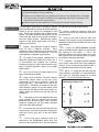
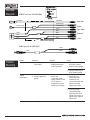
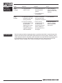
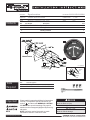
Part Number: 990C0-86B40/86W41
Applications:
Synchronizer
Suzuki Marine Boats
NOTE:
Mounts in standard 3 3/8" hole.
Weight:
Description:
Contents
Ref.
Part Number
1 HRS
Installation Time:
1 lbs
Description
QTY
1. 990C0-86B40/86W41
2. BC0146
Synchronizer
1
Mounting Bracket
1
3.
Mounting Hardware
1
1
RIA
FA
PORT
SLOW
AS
UNC
RP.
CO
VILLE,
CT. MADE IN U
.S.A.
SYNC
7500
-90
-25
A
STBD
SLOW
1
3
2
If so equipped
YELLOW/
RED
YELLOW
BLACK
GRAY
Tools
Required
Ref.
Tools Description
1.
3/8" Nut Driver
2.
Suzuki Terminal Kit
Important
Please read this manual and follow its instructions
carefully. To emphasize special information, the
symbol
and the words WARNING, CAUTION
and NOTE have special meanings. Pay special
attention to the messages highlighted by these signal words:
NOTE: Indicates special information to make
maintenance easier or instructions clear.
NOTE
IS0207B ECR5609 8/2005
09900-28701
Indicates potential hazard that could
result in death or injury.
Indicates potential hazard that could
result in vehicle damage.
Disconnect battery during installation.
Tighten nuts on backclamp only slightly more than you can tighten with your fingers.
Six inch-pounds of torque is sufficient. Over tightening may result in damage to the
instrument and may void your warranty.
Gasket cement or other adhesive is not required to secure tubing to fittings.
Description
The dual engine synchronizer is designed to indicate
engine synchronization extremely accurately when the
speeds of the two engines are compared to each
other. Engine synchronization may be difficult at idle
speeds. For proper operation, both engines must be
of the same type, have the same number of cylinders,
and have similar ignitions. Malfunctioning ignition
systems or high speed "point bounce" will result in
inability to sync properly.
Installation 1.
Location: The synchronizer should be located at
least 18" from a magnetic compass.
Some
interference (erratic operation) may be noticed on the
synchronizer during radio transmissions. This will
neither damage nor degrade it's performance.
2.
Be certain to use stranded, insulated wire not
lighter than 18AWG that is approved for marine use. It
is recommended that insulated wire terminals,
preferably ring type, be used on all connections to the
gauge, except the light which requires a 1/4" female
blade terminal.
3.
Cut a 3-3/8" dia hole in the dash and mount the
gauge with backclamp supplied.
4.
Using a small screwdriver, SLIGHTLY depress
and turn the selector switch on the back of the
synchronizer to the correct position to match the
engine application. (See label on the side of the
synchronizer.) Depressing the switch too hard may
cause damage to gauge! Be sure the selector switch
has locked into the detent at the correct position by
slightly rotating the switch back and forth with the
screwdriver.
5.
If this gauge kit has been supplied with a three
prong connector, slide the connector over the three
instrument studs. Be sure the gray, yellow, and black
bullets are connected to the gray, yellow, and black
wires of the main engine harness.
the yellow wire of the main engine harness.
8.
Connect yellow/red extension lead stud
connector to the PORT signal (SIG) post terminal of
the synchronizer.
9.
Connect the black extension lead stud
connector to the negative (-) post of the synchronizer
and plug the bullet end into the black wire of the main
engine harness.
10.
Connect the GREEN/ORANGE extension
lead to the blade terminal adjacent to the twist-out
light assembly to the positive “+” side of the
instrument lighting circuit and the bullet end to the
boat lighting circuit. No separate ground is required
for the lighting. Reconnect the battery.
11.
Calibration: This gauge has been calibrated
at the factory, and should never need adjustment.
However, If you are experiencing problems refer to
the Calibration section at the end of this manual.
12.
NOTE: To change the light bulb, twist tan
socket assembly one-eighth turn counterclockwise
until it pops out. Bulb pulls straight out of socket
assembly. It is a GE No.194 instrument lamp.
Mounting Hardware Kit
A
x 6
B
x 6
C
x 2
6.
Connect the gray extension lead stud connector
to the positive (+) post of the synchronizer and plug the
bullet end into the gray wire of the main engine
harness.
7.
Connect the yellow extension lead stud
connector to the STARBOARD signal (SIG) post
terminal of the synchronizer and plug the bullet into
A
A
C
B
A
B
Harness
Dia gram
HN0397 revA ecr 4452 03/2004
Yellow/Red
Yellow/Red
Sync Port
Green/Orange
Green/Orange
Green/Orange
Lights
Sync Stbd
Yellow
Black
Yellow
Black
Black
Gray
Gray
Gray
Ground
+14V
Heat shrink tubing
HN0418 rev A ecr 5609 8/05
Yellow
Yellow
Trouble
Shooting
Yellow
Trouble
Inspection
Diagnosis
Action
Gauge Sticks
A. Backclamp may
be too tight.
1. Slightly loosen nuts
holding backclamp.
Check operation.
1. If gauge works and is
not loose in panel,
continue using gauge.
2. If gauge continues to
stick, replace gauge.
Gauge
Inoperative
A. Is power applied to
gauge?
1. Switch the
instrument power
supply switch on and
off. As power is
supplied the pointer
should jump slightly.
1. Check wires to
check they were
installed on the
correct terminals and
power is actually
supplied to gauge.
2 If pointer jumps
(indicating power
supplied), check for
signal from engine. If
signal exists, replace
tachometer.
Trouble shooting continued next page.
Trouble
Shooting
Trouble
Inspection
Diagnosis
Action
Gauge
is Pegged
A. The synchronizer
reads hi or low.
1. The synchronizer is in
the wrong switch
position.
1. Check calibration.
(See the calibration
section at end of this
manual.)
2. The synchronizer is
not calibrated.
Gauge
is Erratic
Calibration
A. Inspect the connection
between the wire and
the ring connector.
1. Fix connection.
1. Check for insulation
that may have been
pushed into connection.
B. Check for excessive
electrical noise caused
by an electrical
appliance set to close
to the gauge. i.e. a
magnetic compass, a
radio transmission.
1. Check wires by
connecting one wire
at a time to the
synchronizer directly
from the battery or
the signal source on
the engine.
1. Relocate offensive
appliance. Please
refer to installation
instructions.
Start the engines and (after an appropriate warm-up period and with shifts in neutral) increase their
speeds to the boat's normal cruising RPM. (Both tachometers must be properly calibrated.) Set the
coarse adjustment switch to the proper position described on it's label. Remove the stop-plug (at the
8-o'clock position on the rear of the case for most) and insert a 5/16" allen wrench into the "fine
adjustment" trumpet, rotating it CW or CCW as necessary to center the synchronizer.