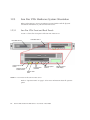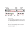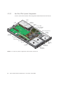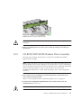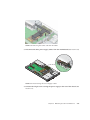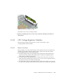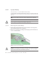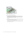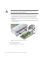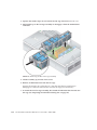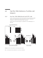
1
Sun FireTM V20z and Sun Fire V40z
Servers
User Guide
Sun Microsystems, Inc.
www.sun.com
Part No. 817-5248-14
March 2005, Revision A
Submit comments about this document at: http://www.sun.com/hwdocs/feedback
Copyright 2005 Sun Microsystems, Inc., 4150 Network Circle, Santa Clara, California 95054, U.S.A. All rights reserved.
Sun Microsystems, Inc. has intellectual property rights relating to technology that is described in this document. In particular, and without
limitation, these intellectual property rights may include one or more of the U.S. patents listed at http://www.sun.com/patents and one or
more additional patents or pending patent applications in the U.S. and in other countries.
This document and the product to which it pertains are distributed under licenses restricting their use, copying, distribution and
decompilation. No part of the product or of this document may be reproduced in any form by any means without prior written authorization of
Sun and its licensors, if any.
Third-party software, including font technology, is copyrighted and licensed from Sun suppliers.
Parts of the product may be derived from Berkeley BSD systems, licensed from the University of California. UNIX is a registered trademark in
the U.S. and in other countries, exclusively licensed through X/Open Company, Ltd.
Sun, Sun Microsystems, the Sun logo, AnswerBook2, docs.sun.com, Sun Fire and Solaris are trademarks or registered trademarks of Sun
Microsystems, Inc. in the U.S. and in other countries.
All SPARC trademarks are used under license and are trademarks or registered trademarks of SPARC International, Inc. in the U.S. and in other
countries. Products bearing SPARC trademarks are based upon an architecture developed by Sun Microsystems, Inc.
The OPEN LOOK and Sun™ Graphical User Interface was developed by Sun Microsystems, Inc. for its users and licensees. Sun acknowledges
the pioneering efforts of Xerox in researching and developing the concept of visual or graphical user interfaces for the computer industry. Sun
holds a non-exclusive license from Xerox to the Xerox Graphical User Interface, which license also covers Sun’s licensees who implement OPEN
LOOK GUIs and otherwise comply with Sun’s written license agreements.
U.S. Government Rights—Commercial use. Government users are subject to the Sun Microsystems, Inc. standard license agreement and
applicable provisions of the FAR and its supplements.
DOCUMENTATION IS PROVIDED "AS IS" AND ALL EXPRESS OR IMPLIED CONDITIONS, REPRESENTATIONS AND WARRANTIES,
INCLUDING ANY IMPLIED WARRANTY OF MERCHANTABILITY, FITNESS FOR A PARTICULAR PURPOSE OR NON-INFRINGEMENT,
ARE DISCLAIMED, EXCEPT TO THE EXTENT THAT SUCH DISCLAIMERS ARE HELD TO BE LEGALLY INVALID.
Copyright 2005 Sun Microsystems, Inc., 4150 Network Circle, Santa Clara, California 95054, États-Unis. Tous droits réservés.
Sun Microsystems, Inc. a les droits de propriété intellectuelle relatants à la technologie qui est décrite dans ce document. En particulier, et sans la
limitation, ces droits de propriété intellectuelle peuvent inclure un ou plus des brevets américains énumérés à
http://www.sun.com/patents et un ou les brevets plus supplémentaires ou les applications de brevet en attente dans les États-Unis et
dans les autres pays.
Ce produit ou document est protégé par un copyright et distribué avec des licences qui en restreignent l’utilisation, la copie, la distribution et la
décompilation. Aucune partie de ce produit ou document ne peut être reproduite sous aucune forme, par quelque moyen que ce soit, sans
l’autorisation préalable et écrite de Sun et de ses bailleurs de licence, s’il y en a.
Le logiciel détenu par des tiers, et qui comprend la technologie relative aux polices de caractères, est protégé par un copyright et licencié par des
fournisseurs de Sun.
Des parties de ce produit pourront être dérivées des systèmes Berkeley BSD licenciés par l’Université de Californie. UNIX est une marque
déposée aux États-Unis et dans d’autres pays et licenciée exclusivement par X/Open Company, Ltd.
Sun, Sun Microsystems, le logo Sun, AnswerBook2, docs.sun.com, Sun Fire et Solaris sont des marques de fabrique ou des marques déposées de
Sun Microsystems, Inc. aux États-Unis et dans d’autres pays.
Toutes les marques SPARC sont utilisées sous licence et sont des marques de fabrique ou des marques déposées de SPARC International, Inc.
aux États-Unis et dans d’autres pays. Les produits portant les marques SPARC sont basés sur une architecture développée par Sun
Microsystems, Inc.
L’interface d’utilisation graphique OPEN LOOK et Sun a été développée par Sun Microsystems, Inc. pour ses utilisateurs et licenciés. Sun
reconnaît les efforts de pionniers de Xerox pour la recherche et le développement du concept des interfaces d’utilisation visuelle ou graphique
pour l’industrie de l’informatique. Sun détient une license non exclusive de Xerox sur l’interface d’utilisation graphique Xerox, cette licence
couvrant également les licenciées de Sun qui mettent en place l’interface d’utilisation graphique OPEN LOOK et qui en outre se conforment aux
licences écrites de Sun.
LA DOCUMENTATION EST FOURNIE «EN L’ÉTAT» ET TOUTES AUTRES CONDITIONS, DÉCLARATIONS ET GARANTIES EXPRESSES
OU TACITES SONT FORMELLEMENT EXCLUES, DANS LA MESURE AUTORISÉE PAR LA LOI APPLICABLE, Y COMPRIS NOTAMMENT
TOUTE GARANTIE IMPLICITE RELATIVE À LA QUALITÉ MARCHANDE, À L’APTITUDE À UNE UTILISATION PARTICULIÈRE OU À
L’ABSENCE DE CONTREFAÇON.
Contents
Preface
xi
How This Book is Organized
Using UNIX Commands
Shell Prompts
xi
xii
xii
Typographic Conventions
Related Documentation
xiii
xiii
Accessing Sun Documentation
Third-Party Web Sites
xiv
xiv
Contacting Sun Technical Support
Sun Welcomes Your Comments
1.
xiv
xiv
Introduction to the Sun Fire™ V20z and Sun Fire V40z Servers
1.1
Safety Guidelines
1.1.1
1.2
1–1
1–1
User Documentation
1–2
Overview of the Sun Fire V20z Server
1–2
1.2.1
Applications
1–3
1.2.2
Sun Fire V20z Features
1.2.3
Sun Fire V20z Hardware System Orientation
1–3
1.2.3.1
Sun Fire V20z Front and Back Panels
1.2.3.2
Sun Fire V20z System Components
1–4
1–4
1–6
iii
1.3
1.4
Overview of the Sun Fire V40z Server
1.3.1
Applications
1.3.2
Sun Fire V40z Features
1.3.3
Sun Fire V40z Server Hardware System Orientation
1–8
1.3.3.1
Sun Fire V40z Front and Back Panels
1.3.3.2
Sun Fire V40z System Components
1–9
1–9
1–11
Server Management
1–12
1–12
1.4.1.1
Service Processor
1–12
1.4.1.2
Operator Panel
1.4.1.3
Front and Back Panel LEDs
1–13
1–18
1.5
Accessory Kits
1.6
Additional Options and Customer-Replaceable Components
1.7
Field-Replacement Units
1–19
1–24
Powering On and Configuring BIOS Settings
2–1
2.1
Powering On the Server
2–1
2.2
Powering Off the Server
2–3
2.3
Escape Sequences for Remote Console Terminal
2.4
BIOS Setup Utility
2.5
iv
1–7
Shared Features of the Sun Fire V20z and Sun Fire V40z Servers
1.4.1
2.
1–7
2–5
2.4.1
Main Menu
2–6
2.4.2
Advanced Menu
2.4.3
Security Menu
2.4.4
Power Menu
2.4.5
Boot Menu
2–14
2.4.6
Exit Menu
2–15
2.4.7
QuickBoot Feature
2–8
2–13
2–14
2–15
Booting From a USB Diskette Device
Sun Fire V20z and Sun Fire V40z Servers—User Guide • March 2005
2–16
2–4
1–21
3.
Maintaining the Sun Fire V20z Server
3–1
3.1
Tools and Supplies Needed
3.2
Powering Off the Server and Removing the Cover
3.2.1
3.3
Server Top-Cover Installation
SCSI ID Assignments
3.4.2
3.3.1.1
Linux-based Server
3.3.1.2
Solaris-based Server
3.5
3–5
3–5
3–5
Versions of the Sun Fire V20z Server
3–6
3.4.1.1
Important Information
3.4.1.2
Solaris 9 OS Install-Time Update for a Super-FRU
Replacement 3–7
3–6
No Mixing of CPU Stepping Versions
3.4.2.1
3.4.3
3–4
3–5
Releases of the Sun Fire V20z Server
3.4.1
3–2
3–3
Locations of Sun Fire V20z Components
3.3.1
3.4
3–1
3–8
Verifying the Stepping Version of the CPU
Support Guide for Half-Length PCI Card Removed
Customer-Replaceable-Unit Replacement Procedures
3.5.1
I/O Board
3.5.2
PCI Card
3.5.3
3–8
3–11
3–12
3–13
3–14
3.5.2.1
Supported PCI Cards
3.5.2.2
Adding or Replacing a PCI Card
SCSI Hard Disk Drive and Carrier
3–14
3–14
3–16
3.5.3.1
Removing an HDD and Carrier
3.5.3.2
Installing an HDD and Carrier
3–16
3–17
3.5.4
SCSI Backplane
3–18
3.5.5
CD-ROM/DVD-ROM/Diskette Drive Assembly
3.5.6
Operator-Panel Board and LCD Display
3.5.7
Power Supply
3.5.8
Cooling Fans
3–21
3–23
3–24
3–26
Contents
v
3.5.9
Memory Voltage-Regulator Modules
3.5.10
CPU Voltage-Regulator Modules
3.5.11
3.5.12
3.6
4.
Before You Start
3.5.10.2
Removing a CPU VRM
3–30
3.5.10.3
Replacing a CPU VRM
3–30
Memory Modules
3–29
3–31
3.5.11.1
Memory Module Population Rules
3.5.11.2
Removing a memory module
3–33
3.5.11.3
Installing a Memory Module
3–33
System Battery
3–31
3–34
3.5.12.1
Removing the System Battery
3–34
3.5.12.2
Replacing the System Battery
3–35
Cable Kit
3.5.14
CPUs and Heatsinks
3–35
3–37
3.5.14.1
One-CPU Configuration
3.5.14.2
Removing a Heatsink and CPU
3.5.14.3
Installing a CPU and Heatsink
Super-FRU
3–37
3–37
3–40
3–42
Sun Fire V20z Indicators, Switches and Jumpers
3.6.1
Sun Fire V20z Motherboard
3.6.2
Clear-CMOS Jumper
3–44
4–1
4.1
Tools and Supplies Needed
4.2
Powering Off the Server and Removing the Cover
4.3
Locations of Sun Fire V40z Components
SCSI ID Assignments
3–44
3–47
Maintaining the Sun Fire V40z Server
4.3.1
vi
3–29
3.5.10.1
3.5.13
3.5.15
3–28
4–1
4–3
4–5
4.3.1.1
Linux-based Server
4.3.1.2
Solaris-based Server
Sun Fire V20z and Sun Fire V40z Servers—User Guide • March 2005
4–5
4–5
4–2
4.4
Releases of the Sun Fire V40z Server
4.4.1
4.4.2
Versions of the Servers
4–6
4.4.1.1
Important Information
4.4.1.2
Solaris 9 OS Install-Time Update for a Super-FRU
Replacement 4–7
4–6
No Mixing of CPU Stepping Versions
4.4.2.1
4.5
4–6
4–8
Verifying the Stepping Version of the CPU
Customer-Replaceable-Unit Replacement Procedures
4.5.1
4.5.2
PCI Card
4–8
4–12
4–13
4.5.1.1
Supported PCI Cards
4–13
4.5.1.2
Adding or Replacing a PCI Card
4.5.1.3
Sun Fire V40z Server PCI Card Slot Locations
4–14
4.5.1.4
Installing a Vertical PCI Card in a Vertical Slot
4–15
4.5.1.5
Installing a Horizontal PCI Card and Riser
SCSI Hard Disk Drive and Carrier
4–14
4–17
4–21
4.5.2.1
Removing an HDD and Carrier
4.5.2.2
Installing an HDD and Carrier
4.5.2.3
Installing an Optional Sixth HDD and Adapter
4.5.3
DVD-ROM/Diskette Drive Assembly
4.5.4
CPU Card
4.5.5
Operator Panel and LCD Assembly
4.5.6
SCSI Backplane Assembly
4.5.7
Cooling Fans
4–21
4–22
4–23
4–24
4–25
4–29
4–30
4–31
4.5.7.1
Fan Numbering
4–32
4.5.7.2
Replacing an Individual Cooling Fan
4.5.7.3
Replacing the Front Fan-Cage Assembly
4.5.7.4
Replacing the Rear Fan-Cage Assembly
4–32
4–34
4–35
Contents
vii
4.5.8
4.5.9
4.5.10
4.5.11
4.5.12
viii
4–37
4.5.8.1
Replacing an Individual Power Supply
4.5.8.2
Replacing a Power-Supply Cage Assembly
Memory Voltage-Regulator Modules
4–37
4–39
4–41
4.5.9.1
Replacing a Memory VRM on the Motherboard
4.5.9.2
Replacing a Memory VRM on the CPU Card
CPU Voltage-Regulator Modules
Before You Start
4.5.10.2
Replacing a CPU VRM on the Motherboard
4.5.10.3
Replacing a CPU VRM on the CPU Card
Memory Modules
4–42
4–44
4–44
4–47
4–49
4.5.11.1
Memory Module Population Rules
4.5.11.2
Replacing a Memory Module on the Motherboard
4.5.11.3
Replacing a Memory Module on the CPU Card
CPUs and Heatsinks
4–49
Replacing a CPU on the Motherboard
4.5.12.2
Replacing a CPU on the Optional CPU Card
4.5.14
Cable Kit
4–63
4–65
4.5.14.1
Remove System Components
4.5.14.2
Remove and Replace the Cables
4.5.14.3
Re-install the Components
Super FRU
4–51
4–52
4–53
4.5.12.1
System Battery
4–41
4–44
4.5.10.1
4.5.13
4.5.15
4.6
Power Supplies and Power-Supply Cage Assembly
4–65
4–68
4–73
4–76
Sun Fire V40z Indicators, Switches and Jumpers
4–78
4.6.1
Sun Fire V40z Motherboard and CPU Card
4.6.2
Clear-CMOS Jumper
4–80
Sun Fire V20z and Sun Fire V40z Servers—User Guide • March 2005
4–78
4–54
4–58
A. System Specifications
A.1
A.2
A–1
Sun Fire V20z Specifications
A–1
A.1.1
Sun Fire V20z Physical Specifications
A.1.2
Sun Fire V20z Power Specifications
A.1.3
Sun Fire V20z Environmental Specifications
Sun Fire V40z Specifications
A–2
A–2
A–3
A.2.1
Sun Fire V40z Physical Specifications
A.2.2
Sun Fire V40z Power Specifications
A.2.3
Sun Fire V40z Environmental Specifications
B. BIOS POST Codes
A–3
A–3
A–4
B–1
C. SCSI BIOS Configuration Utility
C–1
C.1
Starting the SCSI BIOS Configuration Utility
C.2
Using the Configuration Utility
C.3
A–1
C.2.1
User Input
C.2.2
Main Menu
C.2.3
Boot Adapter List
C–5
C.2.4
Global Properties
C–6
C.2.5
Adapter Properties
C.2.6
Device Properties
C–9
C.2.7
RAID Properties
C–12
C–1
C–2
C–3
C–3
C–7
Quitting the SCSI BIOS Configuration Utility
C–14
Contents
ix
D. Supplemental Information
D.1
Index
x
RAID Support
D–1
D–1
D.1.1
LSI Logic’s Integrated RAID Solution
D–2
D.1.2
Integrated Mirroring
D.1.3
Zero-Channel RAID Not Supported
D.1.4
Alternative Internal Drive RAID Configuration For Sun Fire V40z
Servers (Only) D–3
D–2
Index–1
Sun Fire V20z and Sun Fire V40z Servers—User Guide • March 2005
D–3
Preface
How This Book is Organized
Chapter 1 contains an overview of the Sun Fire V20z and Sun Fire V40z servers.
Chapter 2 contains information about how to power on the server and configure the
BIOS.
Chapter 3 contains information about removing and replacing components in a Sun
Fire V20z server.
Chapter 4 contains information about removing and replacing components in a Sun
Fire V40z server.
Appendix A contains information about optimizing system performance.
Appendix B contains a listing of BIOS POST codes.
Appendix C contains reference information about using the Fusion-MPT SCSI BIOS
Configuration Utility.
Appendix D contains supplemental information about hardware.
xi
Using UNIX Commands
This document might not contain information about basic UNIX® commands and
procedures such as shutting down the system, booting the system and configuring
devices. See the following documents for this information:
■
Software documentation that you received with your system
■
Solaris™ operating environment documentation, which is located at:
http://docs.sun.com
Shell Prompts
xii
Shell
Prompt
C shell
machine-name%
C shell superuser
machine-name#
Bourne shell and Korn shell
$
Bourne shell and Korn shell superuser
#
Sun Fire V20z and Sun Fire V40z Servers—User Guide • March 2005
Typographic Conventions
Typeface*
Meaning
Examples
AaBbCc123
The names of commands, files
and directories; on-screen
computer output
Edit your.login file.
Use ls -a to list all files.
% You have mail.
AaBbCc123
What you type, when contrasted
with on-screen computer output
% su
Password:
AaBbCc123
Book titles, new words or terms,
words to be emphasized.
Replace command-line variables
with real names or values.
Read Chapter 6 in the User’s Guide.
These are called class options.
You must be superuser to do this.
To delete a file, type rm filename.
* The settings on your browser might differ from these settings.
Related Documentation
Application
Title
Part Number
Safety information
Important Safety Information for Sun Hardware
Systems
816-7190-xx
Safety notices and
international compliance
certification statements
Sun Fire V20z and Sun Fire V40z Servers—Safety
and Compliance Guide
817-5251-xx
Hardware and system
software installation
Sun Fire V20z and Sun Fire V40z Servers—
Installation Guide
817-5246-xx
Server management
Sun Fire V20z and Sun Fire V40z Servers—
Server Management Guide
817-5249-xx
Operating-system
installation
Sun Fire V20z and Sun Fire V40z Servers—Linux
Operating System Installation Guide
817-5250-xx
Troubleshooting and
diagnostics
Sun Fire V20z and Sun Fire V40z Servers—
Troubleshooting Techniques and Diagnositcs Guide
817-7184-xx
Late-breaking
information
Sun Fire V20z and Sun Fire V40z Servers Release
Notes
817-1771-xx
Preface
xiii
Accessing Sun Documentation
You can view, print or purchase a broad selection of Sun documentation, including
localized versions, at:
http://www.sun.com/documentation
Third-Party Web Sites
Sun is not responsible for the availability of third-party web sites mentioned in this
document. Sun does not endorse and is not responsible or liable for any content,
advertising, products or other materials that are available on or through such sites or
resources. Sun will not be responsible or liable for any actual or alleged damage or
loss caused by or in connection with the use of or reliance on any such content,
goods or services that are available on or through such sites or resources.
Contacting Sun Technical Support
If you have technical questions about this product that are not answered in this
document, go to:
http://www.sun.com/service/contacting
Sun Welcomes Your Comments
Sun is interested in improving its documentation and welcomes your comments and
suggestions. You can submit your comments by going to:
http://www.sun.com/hwdocs/feedback
Please include the title and part number of your document with your feedback:
Sun Fire V20z and Sun Fire V40z Servers—User Guide, part number 817-5248-14
xiv
Sun Fire V20z and Sun Fire V40z Servers—User Guide • March 2005
CHAPTER
1
Introduction to the Sun Fire™ V20z
and Sun Fire V40z Servers
This chapter contains an overview of the Sun Fire™ V20z and Sun Fire V40z servers.
This chapter contains the following sections:
1.1
■
“Overview of the Sun Fire V20z Server” on page 1-2
■
“Overview of the Sun Fire V40z Server” on page 1-7
■
“Shared Features of the Sun Fire V20z and Sun Fire V40z Servers” on page 1-12
■
“Accessory Kits” on page 1-19
■
“Additional Options and Customer-Replaceable Components” on page 1-21
Safety Guidelines
You can safely connect the Sun Fire V20z and V40z servers to an IT Power System.
The use of the black-on-yellow“exclamation-point-in-a-triangle”
symbol on the product indicates a reference to the following
important safety information, concerning National Deviations for
Finland, Norway and Sweden:
■
■
■
■
English: The earthed-style attachment plug on the power-supply cord requires
the socket outlet to be an earthing type.
Finnish: Laite on liitettävä suojamaadoituskoskettimilla varustettuun
pistorasiaan.
Norwegian: Apparatet må tilkoples jordet stikkontakt.
Swedish: Apparaten skall anslutas till jordat uttag.
1-1
1.1.1
User Documentation
For the most up-to-date user documentation, for both the Sun Fire V20z and Sun Fire
V40z servers, please visit the following Web site:
http://www.sun.com/products-n-solutions/hardware/docs/
Servers/Workgroup_Servers/Sun_Fire_V20z/index.html
This site contains the user manuals, the Release Notes and the individual guides for
each of the customer-replaceable units (CRUs).
To verify whether a document on the site is more recent than the document that you
have, refer to the final two digits (the dash-roll) of the Part Number for that
document.
Note – A document explaining the differences among the released versions of the
Sun Fire V20z and Sun Fire V40z servers is also available at this Web site. Refer to
part number (PN) 817-7185.
1.2
Overview of the Sun Fire V20z Server
The Sun Fire V20z is an AMD Opteron™ processor-based enterprise-class 1U 2P
server. The Sun Fire V20z provides performance and value to an enterprise
environment, offering significantly better performance than current 32-bit
Intel-based solutions. The balanced server design maximizes overall performance
through industry-leading I/O options, and delivers compelling real-world workload
performance.
The Sun Fire V20z server includes an embedded service processor (SP), flash
memory, RAM, a separate Ethernet interface and server-management software. It
comes equipped with superior server-management tools for greater control and
minimum total cost of ownership. You can use the command line interface or SNMP
integration with third-party frameworks to configure and manage the platform with
the SP. The dedicated SP provides complete operating-system independence and
maximum availability of server management.
1-2
Sun Fire V20z and Sun Fire V40z Servers—User Guide • March 2005
1.2.1
Applications
The Sun Fire V20z server is ideal for the following applications:
■
■
■
■
■
1.2.2
Web or application hosting
High-performance compute clusters
Offsite/remote server installations
Database workloads
Corporate data centers
Sun Fire V20z Features
TABLE 1-1 shows the main features of the Sun Fire V20z server.
Note – Visit the product Web site for the most up-to-date information on the
product features: http://www.sun.com/servers/entry/v20z.
TABLE 1-1
Sun Fire V20z Server Features
Component
Description
CPU
2 AMD Opteron processors
64-bit x86 architecture
Memory
512 MB–16 GB ECC, registered DDR
(8 slots, 3.05 cm max. height)
Hard Drives
1 or 2 U320 SCSI (only in integrated mirroring configurations—see
“Integrated Mirroring” on page D-2)
SCSI Controller
Embedded U320 controller with potential mirroring support
Network I/O
Dual embedded Gigabit Ethernet
PCI I/O
2 PCI-X expansion slots:
• 1 full-length 66 MHz/64-bit or 133 MHz/64-bit
• 1 half-length 66 MHz/64-bit
Other I/O
Internal CD-ROM (or DVD-ROM) and diskette drive
Embedded SVGA video, keyboard and mouse connectors
Management Service
PowerPC running embedded server and SSL encryption for secure
management from anywhere and two dedicated 10/100 Ethernet
ports to the SP.
Chapter 1
Introduction to the Sun Fire™ V20z and Sun Fire V40z Servers
1-3
1.2.3
Sun Fire V20z Hardware System Orientation
Before performing any service procedures, become familiar with the physical
orientation and features of your Sun Fire V20z server.
1.2.3.1
Sun Fire V20z Front and Back Panels
FIGURE 1-1 shows the front panel of the Sun Fire V20z server.
Hard disk drive 0
Platform power
button
Platform power
indicator LED
FIGURE 1-1
Hard disk drive 1
Locate button
and LED
Operator-panel
buttons
Operator-panel
LCD display
System-fault
LED
Front Panel of the Sun Fire V20z Server
Refer to “Operator Panel” on page 1-13 for more information about the operator
panel.
1-4
Sun Fire V20z and Sun Fire V40z Servers—User Guide • March 2005
FIGURE 1-2 shows the back panel of the Sun Fire V20z server:
AC power connector
SP 10/100
Ethernet
connectors
AC power switch
AC power indicator LED
Keyboard
connector
FIGURE 1-2
Mouse
connector
Locate button
and LED
SP reset
button
Video
connector
Platform Gigabit
Ethernet
connectors
Serial port
USB
connector connector
Back Panel of the Sun Fire V20z Server
Ethernet Port Labelling
It is important to note the labelling of the ethernet ports on the back panel of the Sun
Fire V20z server. As shown on the far right side of the server illustrated in
FIGURE 1-2, interfaces eth1 and eth0 are labelled as “1” on the upper port and “0” on
the bottom port, respectively.
PCI Slot Labelling
The PCI slots are labelled on the server back panel as PCI O (next to the power
supply) and PCI 1 (between the SP and platform ethernet ports). See FIGURE 1-2.
■
■
The slot on the motherboard that corresponds to PCI 0 is identified by the
silkscreen label “Slot 2 133MHz”.
The slot on the motherboard that corresponds to PCI 1 is identified by the
silkscreen label “Slot 1 66MHz”.
Chapter 1
Introduction to the Sun Fire™ V20z and Sun Fire V40z Servers
1-5
1.2.3.2
Sun Fire V20z System Components
FIGURE 1-3 shows the locations of the components inside the Sun Fire V20z chassis.
Power
Supply
PCI Riser
(full length)
I/O
Board
Side Air
Baffle
Memory VRM
Memory Modules
CPU VRM
CPUs and Heatsinks (2)
Center
Air Baffle
0
1
PCI Riser
(half length)
Fans (2)
Memory VRM
1
Memory Modules
CPU VRM
Fans (4)
HD bays (2)
0
SCSI
Backplane
Operator
Panel and
LCD
CD/DVD-FD
Drive Module
SCSI HDDs
with Carriers
FIGURE 1-3
1-6
Location of System Components in the Sun Fire V20z Server
Sun Fire V20z and Sun Fire V40z Servers—User Guide • March 2005
1.3
Overview of the Sun Fire V40z Server
The Sun Fire V40z server is an AMD Opteron Processor-based enterprise-class 3U 4P
server. The Sun Fire V40z server provides performance and value to an enterprise
environment, offering significantly better performance than current solutions. The
AMD Opteron processor implements the x86-64 architecture, which delivers 64-bit
capability. In addition, it delivers significant memory capacity and bandwidth, with
twice the memory capacity and up to three times the memory bandwidth of existing
32-bit x86 servers.
The Sun Fire V40z server includes an embedded Service Processor (SP), flash
memory, RAM, a separate Ethernet interface, shadow password support and
server-management software. It comes equipped with superior server-management
tools for greater control and minimum total cost of ownership. You can use the
command line interface or SNMP integration with third-party frameworks to
configure and manage the platform with the SP. The dedicated SP provides complete
operating-system independence and maximum availability of server management.
1.3.1
Applications
The Sun Fire V40z server is ideal for the following applications:
■
■
■
■
■
Web or application hosting
High-performance compute clusters
Offsite/remote server installations
Database workloads
Corporate data centers
Chapter 1
Introduction to the Sun Fire™ V20z and Sun Fire V40z Servers
1-7
1.3.2
Sun Fire V40z Features
TABLE 1-1 shows the main features of the Sun Fire V40z server.
Note – Visit the product Web site for the most up-to-date information on the
product features: http://www.sun.com/servers/entry/v40z.
1-8
TABLE 1-2
Sun Fire V40z Server Features
Component
Description
CPU
4 AMD Opteron processors
64-bit x86 architecture
Memory
512 MB–64 GB ECC, registered DDR
(16 slots, 3.05 cm max. height)
Hard Drives
Up to 5 U320 SCSI (only in integrated mirroring configurations—see
“Integrated Mirroring” on page D-2)
SCSI Controller
Embedded U320 controller with potential mirroring support
Network I/O
Dual embedded Gigabit Ethernet
PCI I/O
7 PCI-X expansion slots:
• 4 full-length, 133 MHz/64-bit, vertical slots
• 1 full-length, 100 MHz/64-bit, vertical slot
• 1 half-length, 100 MHz/64-bit, vertical slot
• 1 half-length, 66MHz/64-bit, horizontal slot (with riser)
Other I/O
Internal DVD-ROM and diskette drive
Embedded SVGA video, keyboard and mouse connectors
Management Service
PowerPC running embedded server and SSL encryption for secure
management from anywhere and two dedicated 10/100 Ethernet
ports to the SP.
Sun Fire V20z and Sun Fire V40z Servers—User Guide • March 2005
1.3.3
Sun Fire V40z Server Hardware System
Orientation
Before performing any service procedures, become familiar with the physical
orientation and features of your Sun Fire V40z server.
1.3.3.1
Sun Fire V40z Front and Back Panels
FIGURE 1-4 shows the front panel of the Sun Fire V40z server.
USB connector
Hard drive activity indicator LED
Operator-panel
LCD display
Platform power
button and LED
Operator-panel
buttons (3)
Locate button
and LED
System- fault
LED
FIGURE 1-4
Front Panel of the Sun Fire V40z Server
Refer to “Operator Panel” on page 1-13 for more information about the operator
panel.
Chapter 1
Introduction to the Sun Fire™ V20z and Sun Fire V40z Servers
1-9
FIGURE 1-5 shows the back panel of the Sun Fire V40z server:
Vertical PCI card slots (6)
Keyboard
connector
Horizontal PCI card slot
FIGURE 1-5
Video
USB
Serial port
connector connector connector
Mouse
connector
Locate light
button and LED
AC power connectors
(two power supplies shown)
SP reset
button
SP 10/100
Ethernet
connectors
Platform gigabit
Ethernet
connectors
Back Panel of the Sun Fire V40z Server
Ethernet Port Labelling
It is important to note the labelling of the ethernet ports on the back panel of the Sun
Fire V40z server. Referring to the platform gigabit (Gb) ethernet ports at the right
edge of the chassis (see FIGURE 1-5), the lower ethernet interface is eth0 andthe
upper interface is eth1, respectively.
1-10
Sun Fire V20z and Sun Fire V40z Servers—User Guide • March 2005
1.3.3.2
Sun Fire V40z System Components
FIGURE 1-6 shows the locations of the components inside the Sun Fire V40z chassis.
Vertical PCI slots (6)
(Horizontal PCI slot
under power-supply
cage not shown)
Power-supply cage
Rear fan cage
Power
supplies (2)
CPUs with heatsinks
(2 on motherboard)
Memory module slots
(8 on motherboard)
Memory VRM
(2 on motherboard)
Front fan cage
CPU VRM
(2 on motherboard)
Memory VRM
(2 on CPU card)
Memory module slots
(8 on CPU card)
Optional CPU card
(shown removed
from server)
DVD drive/
diskette drive
assembly
CPUs with heatsinks
(2 on CPU card)
Front bezel
Operator panel
Hard disk drives
(5 shown, up to 6
with adapter)
CPU VRM
(2 on CPU card)
FIGURE 1-6
Sun Fire V40z System Components
Chapter 1
Introduction to the Sun Fire™ V20z and Sun Fire V40z Servers
1-11
1.4
Shared Features of the Sun Fire V20z and
Sun Fire V40z Servers
1.4.1
Server Management
Strong server-management capabilities are crucial to maintaining mission-critical
servers. Advance notification of problems and rapid diagnosis and correction are
critical functions to an environment in which a few servers bear most of the
workload. These servers and their extensive server-management capabilities lower
costs by reducing failure and potentially eliminating hands-on management.
1.4.1.1
Service Processor
These servers include a dedicated service processor (SP) for complete
operating-system independence and maximum availability of server management.
The SP is an embedded PowerPC that provides the following:
■
Environmental monitoring of the platform (such as temperatures, voltages, fan
speeds and panel switches)
■
Alert messages when problems occur
■
Remote control of server operations (boot, shutdown and reboot of the server’s
operating system, turning the server’s power on and off, stopping the server’s
boot process in BIOS, and upgrading the BIOS)
The SP runs an embedded version of Linux, and all the server-management
functions are developed as standard Linux applications. Its sole purpose is to
support server management; therefore, the full functionality of the operating system
is not available in the SP. Many familiar applications, such as ftp and telnet, are not
provided as they are not required to support the server-management feature set.
1-12
Sun Fire V20z and Sun Fire V40z Servers—User Guide • March 2005
1.4.1.2
Operator Panel
You can use the operator panel to configure network settings for the service
processor.
■
■
FIGURE 1-1 shows the operator-panel location on the Sun Fire V20z front panel.
FIGURE 1-4 shows the operator-panel location on the Sun Fire V40z front panel.
The drivers for the server must be installed to access these menu options. Some
operator-panel menus are only functional under these conditions:
■
■
■
An external file system is configured with the Network Share Volume (NSV).
The SP update server from the NSV machine is available.
The NSV machine has Java™ Runtime Environment 1.4.2 (or later) installed on it.
The liquid-crystal display (LCD) panel on the operator panel displays menu options
with Menu: appearing in the first line and the menu option in the second line. When
no menu option is available, the first line displays SP information, such as the
IP address, and the second line provides platform information. For example:
123.45.67.89
OS running
TABLE 1-3 shows the operator-panel buttons that are used to navigate through the
menu options.
TABLE 1-3
Button
Operator-Panel Buttons
Function
Back/No
Select
Forward/Yes
Enter
Cancel
The Back/No and Forward/Yes buttons automatically scroll, repeating the action as
long as the button is held down. After the button is held down a few seconds, auto
scrolling begins and rapidly increments or decrements the value.
Chapter 1
Introduction to the Sun Fire™ V20z and Sun Fire V40z Servers
1-13
If a menu or data-entry screen displays for more than 30 seconds with no action
taken, the menu or data entry is cancelled and the display returns to the
idle/background state.
TABLE 1-4 lists the operations you can perform from the operator panel:
TABLE 1-4
Operator-Panel Menu Options
Menu
Menu Options
Description
Server
Shutdown server
Signals the server operating system (OS) to shut down and
power off.
To force the power off in the case in which the OS hangs,
the operator must hold the power button for four seconds.
Reboot server
Signals the server OS to shut down and reboot.
Show DIMM Errs
Displays memory-module errors.
Clear DIMM Errs
Clears memory-module errors.
(For more information, refer to “System-Fault Events” in
the Sun Fire V20z and Sun Fire V40z Servers—
Troubleshooting Techniques and Diagnostics Guide, 817-7184.)
Display Port 80
Displays the last ten Port 80 codes (in hex, 5 per line). Press
any button to clear the display. The display automatically
clears after 30 seconds.
This feature only works in BIOS booting state; to see all the
post codes, run the subcommand sp get port80 -m .
Set SP IP
information
Configures the SP network using DHCP or a static
IP address.
(For more information, refer to Sun Fire V20z and Sun Fire
V40z Servers—Installation Guide, 817-5246.)
Autoconfigure
Propagates SP-configuration information from one SP to
one or more others.
(For more information, refer to Sun Fire V20z and Sun Fire
V40z Servers—Server Management Guide, 817-5249.)
Update SP Flash
Updates SP software. (For more information, refer to Sun
Fire V20z and Sun Fire V40z Servers—Server Management
Guide, 817-5249.)
SP
1-14
Sun Fire V20z and Sun Fire V40z Servers—User Guide • March 2005
TABLE 1-4
Operator-Panel Menu Options (Continued)
Menu
Menu Options
Description
Dump SP
Invokes the Troubleshooting Dump Utility (TDU), which
captures the following information and either sends it to
stdout or stores it in an output file:
• system state table (SST)
• hardware and software component versions
• machine check register values
• CPU trace buffers
• CPU configuration space registers (CSR)
• event log file
• the last good configuration (LGC)
By default, the TDU data is redirected to stdout.
If there is an NFS-mounted directory, the log is placed on a
mounted NFS filesystem, with the following path and file
name: /logs/<sp hostname>/tdulog.tar.
Note: You can also invoke the TDU running the
subcommand sp get tdulog.
Use defaults
Restores SP settings to the default factory configuration.
Note: All current data (users, network configuration, ssh
and events) and IPMI settings are lost, and the SP is
rebooted.
Set SP IP Info
Configures the SP network using DHCP or a static
IP address.
(For more information, refer to Chapter 2 in the Sun Fire
V20z and Sun Fire V40z Servers—Installation Guide,
817-5246.)
Reboot SP
Forces the SP to shut down and reboot.
Note: The platform OS is not affected.
Config Console
Allows you to configure rear-panel serial port to be SP or
platform.
Display Sensors
Displays current sensor readings for each sensor type
• The Left and Right arrow buttons display sensor types.
• The Select button displays the sensor readings in
alphabetical order by unique ID.
• For LEDs, the Select button toggles the state of the LED
on or off.
Chapter 1
Introduction to the Sun Fire™ V20z and Sun Fire V40z Servers
1-15
TABLE 1-4
Operator-Panel Menu Options (Continued)
Menu
Menu Options
Description
Display HW Inv
To use this option:
• The Left and Right arrow buttons display inventory
items.
• The Select button displays the fields that are available for
each item.
• For LEDs, the Select button toggles the state of the LED
on or off.
The individual fields reported are:
Note: Blank fields are skipped.
• name
• attribute
• OEM
• serial number
• part number
• revision
• assembly number
• assembly revision
• firmware ID
• firmware revision
• software ID
• software revision
• date of manufacture
Panel
1-16
Display SW Inv
To use this option:
• The Left and Right arrow buttons display inventory
items.
• The Select button displays the fields that are available for
each item.
• Also displayed is the version and date of installation.
Use SP hostname
Displays the networking host name of the SP in the top line
instead of its numeric IP address.
Sun Fire V20z and Sun Fire V40z Servers—User Guide • March 2005
TABLE 1-4
Operator-Panel Menu Options (Continued)
Menu
Menu Options
Description
Name for LCD
Displays a custom name for the SP in the LCD. (For more
information, refer to Sun Fire V20z and Sun Fire V40z
Servers—Installation Guide.)
Clear LCD name
Removes the user-specified name for the SP. Either the host
name or the IP address displays in the first line.
Rotate IP/Name
The first line of the LCD alternates every five seconds. For
example, the custom name for the LCD or host name
displays, then the IP address, then back, and so on every
five seconds.
If you set the Name for LCD, it displays in the top line. If
you do not set the Name for LCD and you do specify to
Use SP host name, the host name displays in the top line. If
you specify neither the Name for LCD nor the Use SP host
name options, the numeric IP address displays.
Chapter 1
Introduction to the Sun Fire™ V20z and Sun Fire V40z Servers
1-17
1.4.1.3
Front and Back Panel LEDs
TABLE 1-5 describes the functions of the LEDs on the front panel of the server and
TABLE 1-6 describes the functions of the LEDs on the back panel.
■
Refer to FIGURE 1-1 and FIGURE 1-2 for the locations of these LEDs on the Sun Fire
V20z server.
■
Refer to FIGURE 1-4 and FIGURE 1-5 for the locations of these LEDs on the Sun Fire
V40z server.
TABLE 1-5
LED
Description
Platform Power
This LED is lit when the platform power is on.
System Fault
This LED blinks when a severe system fault, such as an over-voltage
condition or an upper temperature limit, is detected.
Refer to “System-Fault Events” in the Sun Fire V20z and Sun Fire
V40z Servers— Troubleshooting Techniques and Diagnostics Guide,
817-7184.
Locate
This LED is lit when you press the Locate button on either the front
or the back of the server. This LED helps you to identify which
system in the rack you are working on in a rack full of servers.
You can also turn on this LED remotely through SP commands (refer
to the Sun Fire V20z and Sun Fire V40z Servers—Server Management
Guide, 817-5249).
TABLE 1-6
1-18
Front Panel LED Functions
Back Panel LED Functions
LED
Description
AC Power Indicator
This LED is lit when the AC power is on.
Locate
This LED is lit when you press the Locate button on either the front
or the back of the server. This LED helps you to identify which
system in the rack you are working on in a rack full of servers.
Sun Fire V20z and Sun Fire V40z Servers—User Guide • March 2005
1.5
Accessory Kits
TABLE 1-7 lists the contents of the accessory kits for the Sun Fire V20z and Sun Fire
V40z servers. The only difference between the two accessory kits is the Setup Poster
for each of the servers.
TABLE 1-7
Contents of the Accessory Kits for the Sun Fire V20z and Sun Fire V40z
Servers
Item
Part Number
Quantity
Delivery
Sun Fire V20z and Sun Fire V40z Servers
Documentation and Support Files CD-ROM.
705-1308
1
CD
At the top level of this CD:
Third-Party License Agreements
The following documents are included in the
directory /documentation :
• Sun Fire V20z and Sun Fire V40z Servers—
Installation Guide
817-5246
• Sun Fire V20z and Sun Fire V40z Servers—User
Guide
817-5248
• Sun Fire V20z and Sun Fire V40z Servers—Server
Management Guide
817-5249
• Sun Fire V20z and Sun Fire V40z Servers—Linux
Operating System Installation Guide
817-5250
• Sun Fire V20z and Sun Fire V40z Servers—Safety and
Compliance Guide
817-5251
• Sun Fire V20z and Sun Fire V40z Servers—
Troubleshooting Techniques and Diagnostics Guide
817-7184
• Pointer Document to Web site with the most current
user documentation
819-1777
• ReadMe for the Bootable Diagnostics CD-ROM
819-1810
• ReadMe for Configuring the Solaris™ 10 OS
Preinstalled on the Server
819-1811
• Installation Guide for the ITU for Solaris™ 9 OS
819-1812
The following files are included in the directory
/support_files :
Chapter 1
Introduction to the Sun Fire™ V20z and Sun Fire V40z Servers
1-19
TABLE 1-7
1-20
Contents of the Accessory Kits for the Sun Fire V20z and Sun Fire V40z
Servers (Continued)
Item
Part Number
Quantity
Delivery
• Support Resources Files
The directory contains important files that are
used in supporting the server. This includes
updated drivers and files for creating a networked
installation server.
For more information, refer to the README.txt
file found in this directory.
N/A
Sun Fire V20z and Sun Fire V40z Servers Network
Share Volume CD-ROM
705-1307
1
CD
Sun Fire V20z and Sun Fire V40z Servers Bootable
Diagnostics CD-ROM
705-1309
1
CD
Sun Installation Assistant CD-ROM
(for Linux OS installations)
705-1183
1
CD
Install-Time Update (ITU) for Solaris™ 9 OS
702-4543
1
Floppy
Diskette
Installation Guide for the ITU for Solaris™ 9 OS
819-1812
1
Printed
Sun Fire V20z and Sun Fire V40z Servers Release Notes
819-1771
1
Printed
Pointer Document to Web site with the most current user
documentation
819-1777
1
Sun Fire V20z and Sun Fire V40z Servers Warranty
Pointer and Privacy Disclaimer Sheet
817-5254
1
Printed
Setting Up the Sun Fire V20z Server (poster)
(Sun Fire V20z server only)
817-5336
1
Printed
Setting Up the Sun Fire V40z Server (poster)
(Sun Fire V40z server only)
817-5337
1
Printed
Important Safety Information for Sun Hardware Systems
816-7190
1
Printed
Sun Fire V20z and Sun Fire V40z Servers Binary Code
License
817-5253
1
Printed
Sun Fire V20z and Sun Fire V40z Servers Third-Party
Software License Agreement
817-5338
1
Printed
Sun Microsystems Software License Agreement
(multilingual)
819-0764
1
Printed
Entitlement for Solaris 10 (3/05) Operating System
819-1755
1
Printed
Sun Fire V20z and Sun Fire V40z Servers—User Guide • March 2005
Printed
1.6
Additional Options and
Customer-Replaceable Components
Note – For the most up-to-date list of available components, visit the following Sun
Web sites:
http://sunsolve.sun.com/handbook_pub/Systems/SunFireV20z/
components.html
and
http://sunsolve.sun.com/handbook_pub/Systems/SunFireV40z/
components.html
Sun offers additional options as well as customer-replaceable components for the
servers. The components for both the Sun Fire V20z and Sun Fire V40z servers are
shown in TABLE 1-8.
To order these parts, contact your local Sun sales representative. You may have a part
that is replaceable under warranty. For specific details regarding your warranty, refer
to:
http://www.sun.com/service/support/warranty/index.html
TABLE 1-8
Sun Fire
V20z
Additional Options and Customer-Replaceable Components for the Sun Fire V20z and
Sun Fire V40z Servers
Sun Fire
V40z
Component
Additional
Options
Customer-Replaceable
Components
CPU/Heatsink Kit
X
• Opteron 242, 1.6 GHz, C0 Stepping
595-7376-xx
F370-6695-xx
X
• Opteron 244, 1.8 GHz, C0 Stepping
595-7336-xx
F370-6670-xx
X
• Opteron 248, 2.2 GHz, C0 Stepping
595-7337-xx
F370-6672-xx
X
• Opteron 244, 1.8 GHz, CG Stepping
594-0368-xx
F370-6783-xx
X
• Opteron 248, 2.2 GHz, CG Stepping
594-0369-xx
F370-6785-xx
X
• Opteron 250, 2.4 GHz, CG Stepping
595-7579-xx
F370-6786-xx
X
• Opteron 252, 2.6 GHz, E Stepping
594-0371-xx
F370-7272-xx
X
• Opteron 844, 1.8 GHz, CG Stepping
N/A
F370-6902-xx
X
• Opteron 848, 2.2 GHz, CG Stepping
N/A
F370-6904-xx
X
• Opteron 850, 2.4 GHz, CG Stepping
N/A
F370-6939-xx
Chapter 1
Introduction to the Sun Fire™ V20z and Sun Fire V40z Servers
1-21
TABLE 1-8
Sun Fire
V20z
Additional Options and Customer-Replaceable Components for the Sun Fire V20z and
Sun Fire V40z Servers (Continued)
Sun Fire
V40z
X
Component
Additional
Options
Customer-Replaceable
Components
• Opteron 852, 2.6 GHz, E Stepping
N/A
F370-7706-xx
Memory
X
X
• 1 GB ECC DDR/333 (2 x 512 MB DIMMs)
595-7339-xx
F370-6643-xx
X
X
• 2 GB ECC DDR/333 (2 x 1 GB DIMMs)
595-7340-xx
F370-6644-xx
• 4 GB ECC DDR/333 (2 x 2 GB DIMMs)
595-7341-xx
F370-6645-xx
X
• 4 GB ECC DDR/333 (2 x 2 GB DIMMs)
595-7599-xx
F370-7063-xx
X
X
• 1 GB ECC DDR/400 (2 x 512 MB DIMMs)
594-0663-xx
F540-6427-xx
X
X
• 2 GB ECC DDR/400 (2 x 1 GB DIMMs)
594-0664-xx
F540-6428-xx
X
X
• 4 GB ECC DDR/400 (2 x 2 GB DIMMs)
594-0665-xx
F540-6429-xx
• 36 GB, Ultra 320 SCSI, 10K rpm
595-7342-xx
F370-6655-xx
X
Hard disk drives (HDDs) and SCSI Backplanes
X
X
X
• 73 GB, Ultra 320 SCSI, 10K rpm
595-7344-xx
F370-6689-xx
X
X
• 73 GB, Ultra 320 SCSI, 15K rpm
595-7578-xx
F370-6941-xx
X
X
• 146 GB, Ultra 320 SCSI, 10K rpm
595-7484-xx
F370-6905-xx
X
X
• 146 GB, Ultra 320 SCSI, 10K rpm
(only supported for the Linux and
Windows OSs)
594-1120-xx
F370-7813-xx
X
X
• 300 GB, Ultra 320 SCSI, 10K rpm
594-0669-xx
F370-7749-xx
• SCSI backplane
N/A
F370-6647-xx
• SCSI backplane
N/A
F370-6926-xx
X
X
PCI Option Cards and Riser Cards
X
X
Ultra SCSI 320 dual port PCI-X card, full length
card
595-7353-xx
F370-6682-xx
X
X
FC-AL 2 Gb/s PCI-X card, low profile 133 MHz
card
595-7377-xx
F370-6697-xx
X
X
Single Gigabit Ethernet PCI-X NIC, low-profile 66
or 133 MHz card
595-7359-xx
F370-6685-xx
X
X
Dual Gigabit Ethernet PCI-X NIC, low-profile 66
or 133 MHz card
595-7360-xx
F370-6687-xx
X
X
Quad Gigabit Ethernet PCI-X NIC, low-profile 66
or 133 MHz card
595-7361-xx
F370-6688-xx
X
X
PCI-X RAID LSI MegaRAID with battery backup
594-0668-xx
F370-7748-xx
1-22
Sun Fire V20z and Sun Fire V40z Servers—User Guide • March 2005
TABLE 1-8
Additional Options and Customer-Replaceable Components for the Sun Fire V20z and
Sun Fire V40z Servers (Continued)
Sun Fire
V20z
Sun Fire
V40z
X
X
X
X
Component
Additional
Options
Customer-Replaceable
Components
Infiniband PCI-X HCA card
595-7580-xx
F370-6943-xx
PCI riser card
N/A
F370-6679-xx
PCI riser card
N/A
F370-6920-xx
Voltage-Regulator Modules (VRMs)
X
X
CPU Voltage-Regulator Module (VRM)
N/A
F370-7746-xx
X
X
Memory Voltage-Regulator Module (VRM)
N/A
F370-7747-xx
Optical Drives
X
CD-ROM/Diskette combo unit
595-7347-xx
F370-6637-xx
X
DVD-ROM/Diskette combo unit
595-7348-xx
F370-6656-xx
DVD-ROM/Diskette combo unit
596-7485-xx
F370-6906-xx
Power supply
N/A
F370-6636-xx
X
Power supply (2nd power supply)
595-7500-xx
F370-6916-xx
X
Power-supply cage assembly
N/A
F370-6921-xx
Cooling fan (individual)
N/A
F370-6639-xx
X
Cooling fan (individual)
N/A
F370-6922-xx
X
Fan-cage assembly, front (holds four fans)
N/A
F370-7803-xx
X
Fan-cage assembly, rear (holds eight fans)
N/A
F370-6924-xx
X
Power Supplies
X
Cooling Fans
X
Miscellaneous
X
I/O board
N/A
F370-6678-xx
X
Operator panel
N/A
F370-6681-xx
Operator-panel assembly
N/A
F370-6925-xx
System Cables kit
N/A
F370-6676-xx
X
System Cables kit
N/A
F370-6584-xx
X
Secondary Planer CPU card
N/A
F370-7778-xx
X
Rail rack-mount kit
595-7378-xx
N/A
X
Cable management arm (for rack mounting)
595-7487-xx
N/A
X
X
X
Chapter 1
Introduction to the Sun Fire™ V20z and Sun Fire V40z Servers
1-23
1.7
Field-Replacement Units
Note – For the most up-to-date list of available components, visit the following Sun
Web sites:
http://sunsolve.sun.com/handbook_pub/Systems/SunFireV20z/
components.html
and
http://sunsolve.sun.com/handbook_pub/Systems/SunFireV40z/
components.html
Field-replacement units (FRUs) are components that should be replaced by qualified
technicians only.
The FRUs available for the Sun Fire V20z and Sun Fire V40z servers are shown in
TABLE 1-9.
To order these parts, contact your local Sun sales representative. You may have a part
that is replaceable under warranty. For specific details regarding your warranty, refer
to:
http://www.sun.com/service/support/warranty/index.html
TABLE 1-9
1-24
Field-Replacement Units for the Sun Fire V20z and Sun Fire V40z Servers
Component
Field-Replaceable Components
Sun Fire V20z Server— Super FRU (chassis swap)
F380-1194-xx
Sun Fire V40z Server— Super FRU (chassis swap)
F380-1206-xx
Sun Fire V20z and Sun Fire V40z Servers—User Guide • March 2005
CHAPTER
2
Powering On and Configuring BIOS
Settings
This chapter contains instructions on powering on and configuring the server BIOS.
Changing the BIOS parameters is only necessary if you want to change the defaults.
Before powering on the server for the first time, follow the instructions in the Sun
Fire V20z and Sun Fire V40z Servers—Installation Guide to set up your server.
This chapter contains the following sections:
■
■
■
■
2.1
“Powering On the Server” on page 2-1
“Escape Sequences for Remote Console Terminal” on page 2-4
“BIOS Setup Utility” on page 2-5
“Booting From a USB Diskette Device” on page 2-16
Powering On the Server
Note – Before powering on a server for the first time, follow the setup instructions in
the Sun Fire V20z and Sun Fire V40z Servers—Installation Guide.
Caution – Before you power on a Sun Fire V40z server for the first time, you must
remove the packaging inserts from the server’s PCI card slots and CPU card slot to
ensure proper air flow and cooling. You can discard these packaging inserts, which
serve as protection during shipping. Do NOT remove the plastic air-baffle inserts
from the PCI slots.
The updated release (chassis PN 380-1206) of the server does not ship with the
packaging insert in the PCI card slots.
2-1
If you want to configure the server BIOS, you must use a PS/2 keyboard for initial
bootup. USB keyboard support is disabled in the BIOS by default. See “BIOS Setup
Utility” on page 2-5 for more information.
Caution – Do not operate this server without all fans, component heatsinks, air
baffles and the cover installed. Severe damage to server components will occur if the
server is operated without adequate cooling mechanisms.
Follow these steps to boot the server:
1. Ensure that an AC power cord is plugged into each power connector on the rear of
the server and into an AC power outlet(s).
2. Power on the server using one of the following two methods, depending on which
server type you have:
■
If you have a Sun Fire V20z server, use these steps:
a. Turn on the AC power switch on the server back panel (see FIGURE 1-2).
This switch provides AC power to the SP and basic hardware.
b. Push and release the platform power button on the server front panel (see
FIGURE 1-1).
This button provides power to the BIOS, operating system and drivers.
■
If you have a Sun Fire V40z server, use this step:
a. Push and release the platform power button on the server front panel (see
FIGURE 1-4).
This button provides power to the BIOS, operating system and drivers. There is
no separate AC power switch on the Sun Fire V40z server; basic AC power is
applied when you plug in a power cord to a power supply.
Note – If this is the first time you are booting the server, the booting stops and
displays a message on the monitor, Operating system not found, and the LCD on
the front panel displays the message, OS Booting. This is normal until after you
install an operating system.
3. When prompted, you can press the F2 key to enter the BIOS Setup Utility or press
the F12 key to boot from the network. To boot from the default boot device, let the
prompt time out and the boot process will continue.
For further information about the BIOS Setup Utility, refer to “BIOS Setup Utility”
on page 2-5. For information about setting up a network PXE installation, see the
Sun Fire V20z and Sun Fire V40z Servers—Linux Operating System Installation Guide.
2-2
Sun Fire V20z and Sun Fire V40z Servers—User Guide • March 2005
2.2
Powering Off the Server
To perform a graceful shutdown of the server while running a Solaris, Linux or
UNIX® operating system, use this procedure.
1. Type the following command:
# poweroff
This command shuts down the OS.
Depending on which OS you are using, you may also have to push the platform
power button on the front panel after the OS shuts down.
2. Do one of the following actions, depending on which model of server you have:
■
If you have a Sun Fire V20z server, turn off the AC power switch on the server
back panel to remove AC power.
■
If you have a Sun Fire V40z server, disconnect all power cords from all power
supplies to remove AC power.
Chapter 2
Powering On and Configuring BIOS Settings
2-3
2.3
Escape Sequences for Remote Console
Terminal
If you are accessing your server using a remote console terminal, you might need to
use the escape sequences shown in TABLE 2-1. If a regular function key is not working
properly, use the escape sequence listed next to it in the table.
You will most likely need to use the escape sequences if you are using a Linux or
Solaris OS.
TABLE 2-1
2-4
Special Keys for Remote Console Terminal
Function Key
Escape Sequence
HOME
<ESC> h
END
<ESC> k
INSERT
<ESC> +
DELETE
<ESC> -
PAGE UP
<ESC> ?
PAGE DOWN
<ESC> /
ALT
<ESC>^A
CTRL
<ESC>^C
F1
<ESC> 1
F2
<ESC> 2
F3
<ESC> 3
F4
<ESC> 4
F5
<ESC> 5
F6
<ESC> 6
F7
<ESC> 7
F8
<ESC> 8
F9
<ESC> 9
F10
<ESC> 0
F11
<ESC> !
F12
<ESC> @
Sun Fire V20z and Sun Fire V40z Servers—User Guide • March 2005
2.4
BIOS Setup Utility
The basic input output system (BIOS) Setup utility can be used to configure BIOS
settings. When the computer is powered on, it is configured with the values stored
in the BIOS ROM by the system BIOS, which gains control at boot time. Changing
these parameters is only necessary if you want to change the defaults.
To change the system parameters, enter the BIOS Setup utility by pressing the F2 key
when prompted, as the system is booting.
Note – If you are using a USB keyboard, the F2 key might not work properly when
entering BIOS Setup unless the F-Lock key is on.
During system boot, you can also press the F12 key to boot the network.
To access the BIOS Setup utility remotely, you can log in by means of an SSH client.
Refer to the Sun Fire V20z and Sun Fire V40z Servers—Server Management Guide, for
more information about managing the server remotely.
From the Main menu screen, you can access other setup screens, such as Security
and Power.
To navigate between items in a menu:
■
■
Use the up and down arrow keys to move among the settings in each menu.
Use the left and right arrow keys to change the options for each setting.
Items that include submenus begin with a triangle icon. To access a submenu, select
the item so that it is highlighted and press Enter.
Note – You can use the Fusion-MPT SCSI BIOS Configuration Utility to change the
default configuration of your SCSI host adapters. You may decide to alter these
default values if there is a conflict between device settings or to optimize system
performance. See Appendix D for details.
Chapter 2
Powering On and Configuring BIOS Settings
2-5
The tables in the following sections describe each parameter setting in the BIOS
Setup Utility.
Note – For NSV version 2.2.0.x and higher, there are certain changes in the menu
options. These changes are called out in the tables.
2.4.1
Main Menu
TABLE 2-2 shows the options that are available from the BIOS Main menu.
TABLE 2-2
2-6
BIOS Main Menu
Menu Option
Description
Default
System Time
Enter the system time (hours:minutes:seconds) in the
specified fields and press Enter to save the data. Use the Tab
key to move to the next field and use Shift+ Tab to move to
the previous field.
Current
time
System Date
Enter the current date in the month, day and year fields.
Press Enter to save the data. Use the Tab key to move to the
next field and use Shift + Tab to move to the previous field.
Current
date
Legacy
Diskette A
Set the type of diskette drive installed as diskette A.
Options include: Disabled, 360KB 5.25 in, 1.2MB 5.25 in,
720KB 3.5 in, 1.44/1.25MB 3.5 in and 2.88MB 3.5 in.
Note: 1.44/1.25MB 3.5-in. references a 1024-byte sector
Japanese media format. This diskette requires a 3-mode
floppy disk drive.
1.44MB
/1.25MB
3.5 in.
Legacy
Diskette B
Note: This
option not
included in
NSV v2.2.0.x
Sets the type of diskette drive installed as diskette B.
Options include: Disabled, 360KB 5.25 in, 1.2MB 5.25 in,
720KB 3.5 in, 1.44/1.25MB 3.5 in and 2.88MB 3.5 in.
Note: 1.44/1.25MB 3.5 references a 1024 byte sector
Japanese media format. This diskette requires a 3-mode
floppy disk drive.
Disabled
Sun Fire V20z and Sun Fire V40z Servers—User Guide • March 2005
TABLE 2-2
BIOS Main Menu (Continued)
Menu Option
Description
Primary
Master
(default:
none)
Set the parameters of the IDE Primary Master/Subordinate
and IDE Secondary Master slots. Press Enter to activate the
submenu screen to configure each of these settings. The
submenu options include:
Primary
Subordinate
(default:
none)
• Type: The type of IDE hard drive. Options include: Auto
(allows BIOS to automatically determine the hard drive’s
capacity, number of heads, etc.), User, a number from 1 to
39 to select a predetermined type of hard drive,
CD/DVD-ROM, ATAPI Removable and IDE Removable.
Auto
Multisector
• Multi-Sector Transfers: The number of transfer sectors.
Options include: Disabled, 2, 4, 8 and 16 sectors.
Disabled
• LBA Mode Control: Determines whether BIOS will access
the IDE Primary Master Device via LBA mode. Options
include: Enabled and Disabled.
Disabled
• 32-bit I/O: Selects the 32-bit I/O operation. Options
include: Enabled and Disabled.
Disabled
• Transfer Mode: Selects the transfer mode.
Options include: Standard, Fast PIO1, Fast PIO2, Fast
PIO3, Fast PIO4, FPIO3/DMA1 and FPIO4/DMA2.
Standard
• Ultra DMA Mode: Selects Ultra DMA Mode. Options
include: Disabled, Mode 0, Mode 1, Mode 2, Mode 3,
Mode 4, Mode 5 and Mode 6.
Disabled
HDD Post
Write Buffer
Enable or disable HDD Post Write Buffer support.
Enabled
Large Disk
Access Mode
For UNIX, Novell Netware or other OSs, select Other. If you
are installing new software and the drive fails, change this
selection and try again. Different OSs require different
representations of drive geometries.
Options include: DOS and Other.
DOS
Boot
Summary
Enable or disable display of the system configuration on
boot.
Disabled
System
Memory
Displays how much system memory is recognized as
present in the system.
Current
memory
Extended
Memory
Displays how much extended memory is recognized as
present in the system.
Current
memory
Secondary
Master
(default:
CD-ROM)
Default
Chapter 2
Powering On and Configuring BIOS Settings
2-7
2.4.2
Advanced Menu
TABLE 2-3 shows the options that are available from the Advanced menu.
TABLE 2-3
2-8
BIOS Advanced Menu
Menu Option
Description
Default
Reset
Configuration
Data
Clears the Extended System Configuration Data (ECSD).
Options include: Yes and No.
No
Multiprocessor
Specification
Note: This
option is not
included in NSV
v2.2.0.x
Configures the MP Specification revision level. Some OSs
require 1.1 for compatibility. Options include: 1.4 and 1.1.
1.4
PCI Interrupts
From MP Table
Configures the MP Table with PCI Interrupt entries.
Options include: Yes and No.
Yes
Machine Check
Stop
If enabled, system stops when a machine check error
occurs. If disabled, system reboots when a machine check
error occurs. Only applies if your operating system does
not have its own machine check handler.
Double fault scenario: If enabled, the system stops when a
second fatal machine check error occurs while processing a
first fatal machine check (a double fault). If disabled, the
system reboots during a double fault. This also applies to
what occurs on the first fatal machine check if your
operating system does not have its own machine check
handler.
Disabled
QuickBoot
Mode
Allows the system to skip tests while booting. Options
include: Enabled and Disabled.
Disabled
Error Message
Handling
Disabled allows system to automatically continue to boot
after displaying a detected error. The other options display
the SETUP entry or resume boot prompt, then wait
for the specified period of time or forever, while a user
chooses the action to take.
Options include: Disabled, Wait 5 seconds, Wait 30
seconds, Wait Forever
Wait 30
seconds
Diagnostics
Boot Mode
Note: This
option is new in
NSV v2.2.0.x
Diagnostics Boot Mode can be enabled to provide platform
diagnostics (CD Diags) with the same BIOS support
provided to SP Diags. The default (Disabled) reflects that
the platform is usually booted normally and not in
diagnostic-support mode.
Enabling this option is effective only for the next boot,
after which it is reset to Disabled.
Disabled
Sun Fire V20z and Sun Fire V40z Servers—User Guide • March 2005
TABLE 2-3
BIOS Advanced Menu (Continued)
Menu Option
Description
Default
Chipset
Configuration
Caution: Do not
change the
settings unless
you are sure of
what you are
doing. Setting
items on this
menu to
incorrect values
may cause your
system to
malfunction.
Options for advanced chipset features. Options include:
• SRAT Table: Enables the ACPI 2.0 Static Resource
Affinity Table for OSs that support an SRAT and will
disable node interleaving. Disabled allows for node
interleaving. Options include: Enabled and Disabled.
Enabled
• Node Interleave: If set to Auto, node interleaving will be
enabled if memory sizes match, SRAT table is disabled
and if DRAM ECC scrubbing is disabled. Options
include: Auto and Disabled.
Disabled
• Bank Interleave: If set to Auto, bank interleaving is
enabled if the memory size and type match. Options
include: Auto and Disabled.
Auto
• ECC: Enable or disable ECC check/correct mode. This is
a global enable function for all blocks within the CPU
core and North Bridge.
Enabled
• DRAM ECC: If all memory in the system supports ECC
(x72), enabling invokes initial scrub DRAM and enables
system requests to DRAM to be checked and/or
corrected. Options include: Enabled and Disabled.
Enabled
• ECC Scrub Redirection: Enable or disable ECC Scrubber
to correct errors detected in DRAM during normal CPU
requests (foreground scrubbing).
Enabled
• Chip-Kill: Enabled or disable the ChipKill ECC on nodes
with all x4 ECC capable DIMMS.
Enabled
• DCACHE ECC Scrub CTL: Sets the rate of background
scrubbing for DCACHE lines. Options include: 5.12 µs,
10.2 µs, 20.5 µs, 41.0 µs, Disabled, 640 ns, 1.28 µs, 2.56 µs.
5.12 µs
• L2 ECC Scrub CTL: Sets the rate of background
scrubbing for L2 cache lines. Options include: 10.2 µs,
20.5 µs, 41.0 µs, 81.9 µs, Disabled, 1.28 µs, 2.56 µs,
5.12 µs.
10.2 µs
• DRAM ECC Scrub CTL: Sets the rate of background
scrubbing for DRAM (in addition to normal ECC
scrubbing from system requests). Background agent
works independently of CPU requests and bus masters,
but cannot be enabled without first enabling DRAM
ECC. Options include: 163.8 µs, 327.7 µs, 655.4 µs, 1.31
ms, Disabled, 20.5 µs, 41.0 µs, 81.9 µs.
163.8 µs
• No Spec. TLB Reload: When this is at the default
(Disabled), the translation look-aside buffer (TLB) is
reloaded. When enabled, TLB reloading is turned off.
Disabled
Chapter 2
Powering On and Configuring BIOS Settings
2-9
TABLE 2-3
BIOS Advanced Menu (Continued)
Menu Option
Description
I/O Device
Configuration
Options for peripheral menu. Options include:
Note: Sun Fire
V40z servers
include a serial
port B; this
option does not
appear for Sun
Fire V20z
servers.
2-10
Default
• PS/2 Mouse: Disabled prevents any installed PS/2 mouse
from functioning, but frees up IRQ 12. Enabled forces
the PS/2 mouse port to be enabled regardless of
whether a mouse is present. Auto Detect enables the
PS/2 mouse only if present. OS Controlled only displays
if the OS controls the mouse.
Enabled
• Floppy Disk Controller: Options include: Enabled (user
configuration), Disabled (no configuration), Auto (BIOS
or OS chooses configuration) and OS Controlled
(displayed when controlled by the operating system).
Enabled
• USB Host Controller: Enables or disables the USB
hardware. Disabled resources are freed for other users.
Enabled
• USB BIOS Legacy Support: Enables or disables support
for USB devices. Enable for use with a non-USB-aware
OS such as DOS, Linux or Solaris.
Disabled
• Onboard PCI IDE: Enables the integrated local bus IDE
adapter. Options include: Disabled, Primary, Secondary,
Both.
IDE: Both
• Serial Port A: Assigns control of serial port A. Options
include: Enabled, Auto or Disabled. When enabled, you
must also select the Base I/O Address and Interrupt for
serial port A.
- Base I/O address:
- Interrupt:
Enabled
• Serial Port B: Assigns control of serial port B. Options
include: Enabled, Auto or Disabled. When enabled, you
must also select the Base I/O Address and Interrupt for
serial port B.
- Base I/O address:
- Interrupt:
Enabled
• Ethernet Adapter 0 MAC: Displays the Onboard Ethernet
Adapter 0 MAC address.
MAC
address
• Ethernet Adapter 1 MAC: Displays the Onboard Ethernet
Adapter 1 MAC address.
MAC
address
Sun Fire V20z and Sun Fire V40z Servers—User Guide • March 2005
3F8
IRQ4
2F8
IRQ3
TABLE 2-3
BIOS Advanced Menu (Continued)
Menu Option
Description
Default
PCI
Configuration
Note: The Sun
Fire V20z server
has two PCI
slots; the Sun
Fire V40z server
has seven slots.
Setup items for configuring the specific PCI device slots:
• Option ROM Scan: When disabled, the device is not
bootable but is still usable under the OS. When enabled,
initializes the device expansion ROM; makes device
bootable.
Enabled
• Enable Master: Enables or disables the selected device as
a PCI bus master.
Enabled
• Latency Timer: Minimum guaranteed time slice allotted
for bus master in units of PCI bus clocks. Options
include: 0040h, 0060h, 0080h, 00A0h, 00C0h, 00E0h,
default and 0020h.
0040h
Setup items for configuring the Embedded Broadcom
device GBIT 0 or GBIT 1:
• Option ROM Scan: When disabled, the device is not
bootable but still usable under the OS. When enabled,
initializes device expansion ROM; makes device
bootable.
Enabled
Reserve specific IRQs for use by legacy ISA devices:
• PCI/PNP IRQ Exclusion: Reserves the specified IRQ for
use by legacy ISA devices.
Available
• PCI/PNP UMB Exclusion: Reserves the specified block of
upper memory for use by legacy ISA devices.
Available
Note: This
option is new in
NSV v2.2.0.x
Option ROM Expansion: If errors occur when option ROMs
are initialized, choose Extended to increase memory
during ROM expansion time.
Caution: The server may hang when Extended is used
with some option ROMs.
Normal
Note: This
option is new in
NSV v2.2.0.x
8131 Errata 56 PCLK: This indicates a card problem. The
BIOS will fix the problem or will turn it off. If you select
Enabled, the BIOS will not turn it off.
Disabled
Chapter 2
Powering On and Configuring BIOS Settings
2-11
TABLE 2-3
2-12
BIOS Advanced Menu (Continued)
Menu Option
Description
Console
Redirection
Additional setup to configure console. Options include:
Default
• COM port address: If enabled, the console uses a port on
the motherboard. Options include: Disabled, On-board
COM A, On-board COM B.
On-board
COM A
• Console connection: Indicates whether the console is
connected directly to the system or through a modem.
Options include: Direct and Modem.
Direct
• Baud rate: Enables the specified baud rate. Options
include: 300, 1200, 2400, 9600, 19.2K, 38.4 K, 57.6K, 115.2
K.
9600
• Flow control: Enables flow control. Options include:
None, XON/XOFF, CTS/RTS.
None
• Console type: Enables the specified console type. Options
include: VT100, VT100 8 bit, ANSI 7 bit, ANSI, VT100
plus, UTF8.
vt100 plus
• Continue CR after POST: Normally, console redirection is
off before the OS loads. Set this item to On to
troubleshoot the BIOS boot problems. Note: the OS
loader typically interrupts console redirection once it
starts.
Options include: On and Off.
On
Sun Fire V20z and Sun Fire V40z Servers—User Guide • March 2005
2.4.3
Security Menu
TABLE 2-4 shows the options that are available from the BIOS Security menu.
TABLE 2-4
BIOS Security Menu
Menu Option
Description
Default
Supervisor
Password Is:
Displays whether a supervisor password has
been entered for the system. Clear means
such a password has not been used and Set
means a supervisor password has been
entered for the system.
Clear
User Password
Is:
Displays whether a user password has been
entered for the system. Clear means such a
password has not been used and Set means a
user password has been entered for the
system.
Clear
Set Supervisor
Password
Supervisor password controls access to the
Setup Utility. Enter the Supervisor’s
password to set or change it. Enables access
to BIOS.
Enter
Set User
Password
Enter the user’s password to set or change it.
Enables access to the system at boot time.
Enter
Password on
Boot
Allows you to require a password to be
entered when the system boots. Options
include: Enabled (password required) and
Disabled (password not required).
Disabled
Fixed Disk Boot
Sector
May offer protection against viruses when
set to Write Protect, which protects the boot
sector on the hard drive from having a virus
written to it. Options include: Write Protect
and Normal.
Normal
Chapter 2
Powering On and Configuring BIOS Settings
2-13
2.4.4
Power Menu
TABLE 2-5 shows the options that are available from the BIOS Power menu.
TABLE 2-5
2.4.5
BIOS Power Menu
Menu Option
Description
Default
Resume on
Time
Wakes the system up at the specified time. Options
are On or Off.
Off
Resume Time
If turned on, specifies the time you want the system
to wake up.
00.00.00
Resume Date
If turned on, specifies the date you want the system
to wake up.
00/00/0000
After Power
Failure
Sets the mode of operation if an AC power loss
occurs. Three modes are available:
- Stay off: returns the system to an off state.
- Power on: returns the system to a full on state.
- Last state: returns the server to the state it was at
before the power went off.
Stay off
Boot Menu
TABLE 2-6 shows the options that are available from the BIOS Boot menu. To change
the order of the boot items, select an item and press the plus (+) key to move the
item up in the order and the minus (-) key to move the item down in the order.
TABLE 2-6
2-14
BIOS Boot Menu
Menu Option
Description
Default Boot Order
Removable Devices (Floppy)
Boot from the diskette drive
First boot device
CD-ROM Drive
Boot from the CD/DVD-ROM
Second boot device
Hard Drive
Boot from the hard disk
Third boot device
Network Boot
Boot from a networked device
Networked boot device
MBA v7.0.x Slot 0210
Boot from the on-board NIC #1
Fourth boot device
MBA v7.0.x Slot 0218
Boot from the on-board NIC #2
Fifth boot device
Sun Fire V20z and Sun Fire V40z Servers—User Guide • March 2005
2.4.6
Exit Menu
TABLE 2-7 shows the options that are available from the BIOS Exit menu.
TABLE 2-7
2.4.7
BIOS Exit Menu
Menu Item
Description
Exit Saving
Changes
Exit System Setup and save changes to CMOS.
Exit Discarding
Changes
Exit System Setup without saving changes.
Load Setup
Defaults
Load defaults for all setup items.
Discard
Changes
Load previous values from CMOS for all setup items.
Save Changes
Save setup data to CMOS.
QuickBoot Feature
The QuickBoot feature, which disables BIOS memory tests, defaults to disabled,
which is the recommended setting.
Note – If you choose to set Quickboot to enabled, you need to perform the
following steps to disable the QuickBoot feature whenever you add new memory, so
that the new memory configuration can be tested.
1. Boot the server and run BIOS Setup by pressing the F2 key during the boot
process.
2. From the Advanced menu, disable the QuickBoot feature.
Now the BIOS will run at least one full memory test for your new memory when the
server is rebooted.
3. Press F10 to save the changes and exit.
The system will automatically reboot and run the memory configuration tests.
4. When all memory passes the tests, press the F2 key to enter BIOS Setup and reenable the QuickBoot option in the BIOS Advanced menu, if needed.
Chapter 2
Powering On and Configuring BIOS Settings
2-15
2.5
Booting From a USB Diskette Device
Only one diskette device is bootable on these servers. By default, the internal
diskette device is the only device from which you can boot.
To change the assignment of the diskette devices so that the server boots from a USB
diskette device, rather than the internal diskette device, perform the following steps:
1. Attach the USB diskette device.
2. Power on and reboot the system.
3. Press the F2 key to enter the BIOS Setup utility.
4. From the Advanced menu, choose I/O Device Configuration.
5. Change the USB Host Controller and USB BIOS Legacy Support submenu options
to Enable.
6. Press the F10 key to save your changes and reboot the server.
7. When prompted, press the F2 key to enter the BIOS Setup utility.
8. In the Boot menu, select Removable Devices.
9. Select USB Floppy from the Removable Devices submenu, and press the plus (+)
key to move USB Floppy to the top of the list of devices.
10. Press the F10 key to save your changes and reboot.
The USB diskette device is bootable as drive A. If left enabled, the internal diskette
drive becomes drive B and is not bootable.
Note – To change the internal diskette drive to be drive A again, disconnect the USB
diskette device and reboot the server. The internal diskette device will be assigned to
drive A, and if you reattach the USB diskette device, it will be assigned to drive B.
2-16
Sun Fire V20z and Sun Fire V40z Servers—User Guide • March 2005
CHAPTER
3
Maintaining the Sun Fire V20z
Server
This chapter describes how to add, replace and configure components in the Sun Fire
V20z and V40z servers server after it has been set up.
Caution – Before touching or replacing any component inside the server, disconnect
all external cables. If possible, place the server on a grounded electrostatic-discharge
(ESD) pad and ALWAYS wear a properly grounded, antistatic wrist strap.
For instructions on maintaining a Sun Fire V40z server, see Chapter 4.
This chapter contains the following sections:
■
■
■
■
■
■
“Tools and Supplies Needed” on page 3-1
“Powering Off the Server and Removing the Cover” on page 3-2
“Releases of the Sun Fire V20z Server” on page 3-5
“Locations of Sun Fire V20z Components” on page 3-4
“Customer-Replaceable-Unit Replacement Procedures” on page 3-12
“Sun Fire V20z Indicators, Switches and Jumpers” on page 3-44
To determine and isolate a faulty component, refer to the Sun Fire V20z and Sun Fire
V40z Servers—Troubleshooting Techniques and Diagnostics Guide (817-7184).
3.1
Tools and Supplies Needed
■
■
■
#2 crosshead screwdriver
Antistatic wrist strap
Alcohol pads (for CPU replacement only)
3-1
3.2
Powering Off the Server and Removing
the Cover
Perform this procedure to observe safety guidelines when you are powering off the
system and removing the cover for a maintenance procedure in this chapter:
1. If the system OS is running, perform a shutdown of the OS, then press and
release the platform power button on the front panel.
2. Turn off all peripheral devices connected to the system.
3. Turn off the AC power switch on the rear panel of the server (see FIGURE 1-2).
Disconnect the server from the electrical outlet.
4. Turn off power to any attached peripherals.
5. Label and disconnect all peripheral cables and all telecommunication lines
connected to I/O connectors or ports on the back panel of the system.
Caution – The system’s printed circuit boards and hard disk drives contain
components that are extremely sensitive to static electricity.
6. Before handling components, attach a wrist strap to a chassis ground (any
unpainted metal surface).
7. Pull the cover toward the server front slightly, then press the cover latch release
button with your right thumb (A) and slide the cover towards the rear of the
chassis until it contacts the stop (B) (see FIGURE 3-1).
8. Lift the cover up and remove it.
A
B
FIGURE 3-1
3-2
Removing the Cover of the Sun Fire V20z Server
Sun Fire V20z and Sun Fire V40z Servers—User Guide • March 2005
3.2.1
Server Top-Cover Installation
When replacing the top cover on the Sun Fire V20z server after component
installation, use caution to avoid damaging the cover or server components.
Remove all peripheral cables from PCI cards before installing the cover. If you install
the server cover with PCI card cables installed, a lip on the edge of the server cover
and the EMC foam gasket inside that lip may catch parts of the PCI card connectors
and, in some cases, may deform the server cover seal or damage the connector
latches.
Ensure that the power-supply cable is properly installed. The server cover may not
close properly or may be difficult to close, and server performance may be affected if
the power-supply cable is not properly installed.
The power-supply cable must be routed and pressed down such that it does not
interfere with the cover installation. The power-supply cable must be tucked into a
position such that the cable and its associated tie-wraps are not below the top
surface of the power supply. Rotate the tie-wraps downward so that they do not
protrude above the cable itself.
Chapter 3
Maintaining the Sun Fire V20z Server
3-3
3.3
Locations of Sun Fire V20z Components
Refer to FIGURE 3-2 to locate components before performing the remove and replace
procedures.
The following figure indicates the location of each of these components:
Power
Supply
PCI Riser
(full length)
I/O
Board
Side Air
Baffle
Memory VRM
Memory Modules
CPU VRM
CPUs and Heatsinks (2)
Center
Air Baffle
0
1
PCI Riser
(half length)
Fans (2)
Memory VRM
1
Memory Modules
CPU VRM
Fans (4)
HD bays (2)
0
SCSI
Backplane
Operator
Panel and
LCD
CD/DVD-FD
Drive Module
SCSI HDDs
with Carriers
FIGURE 3-2
3-4
Locations of System Components in Sun Fire V20z Server, Top-Down View
Sun Fire V20z and Sun Fire V40z Servers—User Guide • March 2005
3.3.1
SCSI ID Assignments
The ID assignments for the SCSI hard-disk-drive connectors on the SCSI backplane
are shown in FIGURE 3-3, when viewing the HDDs from the front of the server.
■
SCSI slot 0 is the left drive bay.
■
SCSI slot 1 is the middle drive bay, next to the CD-ROM/Diskette Drive assembly.
SCSI slot 0
FIGURE 3-3
3.3.1.1
SCSI slot 1
CD-ROM/Diskette
SCSI Slot Numbering for HDDs
Linux-based Server
If you have a single SCSI HDD, the drive can be inserted in either slot. If you have
two HDDs, the drive with the OS boot sector must be installed in the
lowest-numbered slot among the populated slots.
3.3.1.2
Solaris-based Server
The Solaris boot disk must be installed in SCSI slot 0.
3.4
Releases of the Sun Fire V20z Server
This chapter applies to:
■
■
■
the original release (chassis part number [PN] 380-0979) of the server
the first updated release (chassis PN 380-1168) of the server
the second updated release (chassis PN 380-1194) of the server
The following sections highlight some issues that you should take into account when
performing the remove-and-replace procedures in this chapter.
Chapter 3
Maintaining the Sun Fire V20z Server
3-5
3.4.1
Versions of the Sun Fire V20z Server
A number of different versions of the Sun Fire V20z server have been released. Due
to changes on the motherboard as well as in the BIOS and firmware, a number of
components—such as memory VRMs and CPU VRMs—are not interchangeable
among the various releases.
The chassis part number (PN) is labelled on the front panel of the server, near the
CD-ROM/DVD-ROM/Diskette Drive assembly.
TABLE 4 explains the components available for each of the server releases.
TABLE 4
Components Available for Server Releases
Super FRU
Chassis PN
Family of CPU
(stepping version)
CPU VRM
required (PN)
Type of
Memory DIMM
Memory VRM
required (PN)
380-0979
C0
F370-6680
DDR 333
F370-6646
380-1168
CG
F370-6680
DDR 333
F370-6646
380-1194
E
F370-7746
DDR 333
DDR 400
F370-7747
3.4.1.1
Important Information
Please take note of the following items.
Super FRU chassis PN 380-0979 (Sun Fire V20z server)
For this release:
■
■
■
Super FRU chassis PN F380-0979 is sent as a replacement for chassis PN 380-0979
only.
You can only use CPU stepping version C0.
You can only use Registered DDR 333 memory DIMMs.
Super FRU chassis PN 380-1168 (Sun Fire V20z server)
For this release:
■
■
■
■
3-6
Super FRU chassis PN F380-1168 is sent as a replacement for chassis PN 380-1168.
If necessary, it can be sent as a replacement for chassis PN 380-0979.
You can use CPU stepping versions C0 and CG in this Super FRU replacement. To
use stepping version CG, the server must be running BIOS version 1.27.9 or
higher.
You cannot use CPU stepping version E in this release.
You can only use Registered DDR 333 memory DIMMs.
Sun Fire V20z and Sun Fire V40z Servers—User Guide • March 2005
Super FRU chassis PN 380-1194 (Sun Fire V20z server)
For this release:
■
■
■
■
■
■
3.4.1.2
Super FRU chassis PN F380-1194 is sent as a replacement for chassis PN 380-1194
only.
You can only use CPU stepping version E.
You cannot use CPU stepping versions C0 and CG.
With CPU stepping version E, you must use the CPU VRM PN F370-7746 (due to
the higher wattage requirements for this CPU).
You can use Registered DDR 333 or DDR 400 memory DIMMs.
In this Super FRU release, you must use the memory VRM PN F370-7747, due to
the higher speed of the DIMMs. This is the supported memory VRM for this
Super FRU, and it covers both the DRR 333 and DDR 400 memory DIMMs.
Solaris 9 OS Install-Time Update for a Super-FRU
Replacement
If you want to install the Solaris™ 9 Operating System (OS) on an updated release of
the Sun Fire V20z server (either chassis PN 380-1168 or PN 380-1194), you must
download a Solaris OS Install-Time Update (ITU) from the Web site. This ITU is
required during OS installation.
If you want to install the Solaris 9 OS on an updated release of the Sun Fire V40z
server, you must also download this Solaris OS ITU from the Web site. This ITU is
required during OS installation.
The Solaris OS ITU is available from the product Web site:
http://www.sun.com/servers/entry/v20z/downloads.html
Chapter 3
Maintaining the Sun Fire V20z Server
3-7
3.4.2
No Mixing of CPU Stepping Versions
A number of different versions of the Sun Fire V20z server have been released with
CPUs of different stepping versions.
If you order an CPU X-option to add or replace a CPU in your server, do not mix
CPUs of different stepping versions.
Caution – A new heatsink ships for the stepping version “E” CPU. Ensure that you
do not use an old heatsink on a stepping version “E” CPU.
Before ordering a new or replacement CPU, verify the stepping version of your
CPU(s) and then order the same stepping version.
Due to the power requirements and height restrictions, the stepping version “E”
CPUs work only in the Sun Fire V20z server release PN 380-1194.
In a two-CPU configuration of the Sun Fire V20z server, both CPUs must be the same
stepping version and the same speed.
3.4.2.1
Verifying the Stepping Version of the CPU
You can verify the stepping version of the CPU in a local server or on a remote
server.
3-8
Sun Fire V20z and Sun Fire V40z Servers—User Guide • March 2005
Verifying the Stepping Version In a Local Server
To verify the stepping version of your CPU(s) in a local server (with KVM attached):
1. Power on or reboot your server.
A message similar to the following example appears on the screen, and the memory
test begins.
This sample shows the output for a Sun Fire V20z server.
----------------PhoenixBIOS 4.0 Release 6.0
Copyright 1985-2002 Phoenix Technologies Ltd.
All Rights Reserved
Production RELEASE: System BIOS Revision = V1.30.5
SP Interface (PRS) Revision = 92
SP - BIOS Interface Active
xxxxxxxxxxxxxxxxxxxxxxxxxx
xx
Sun Microsystems
xx
xx
Sun Fire V20z
xx
xxxxxxxxxxxxxxxxxxxxxxxxxx
CPU = AMD Opteron(tm) Processor 250
2 Processors Detected, CG - CG
PCIX - Slot1: PCIX-66
Slot2: PCIX-133
4031M System RAM Passed
1024K Cache SRAM Passed
ATAPI CD-ROM: CD-224E
Mouse initialized
-------------------------
2. During the memory test, hit the Pause key.
3. Verify the stepping version of the CPUs in the line similar to the following
examples:
2 Processors Detected, CG - CG
or
2 Processors Detected, E4 - E4
4. To continue with the reboot, hit any key.
Chapter 3
Maintaining the Sun Fire V20z Server
3-9
Verifying the Stepping Version In a Remote Server
To verify the stepping version of your CPU(s) in a remote server:
1. Enable the Serial-Over-Lan(SOL) feature on the SP.
For more information, refer to the “Serial Over LAN” section in Chapter 4 of the Sun
Fire V20z and Sun Fire V40z Servers—Server Management Guide (817-5249).
2. Launch an SOL session from a SP command-line interface (CLI) to connect to the
platform console remotely.
3. Run the following command.
platform set console -s sp -e -S baud rate
where baud rate is the value that you have set in the BIOS settings; the default baud
rate in the BIOS settings is 9600.
For example, if the baud rate in your BIOS settings is set to the default value, you
would enter:
platform set console -s sp -e -S 9600
Note – This command changes the baud-rate value for the SP so that it matches the
baud rate in the BIOS settings. It does not change the baud rate in the BIOS settings.
4. Run the following command.
platform get console
5. Verify that the correct baud rate appears in the Speed column. Using the example
above, the output should appear as follows:
Rear Panel Console Redirection
Speed
Pruning
Log Trigger
SP Console Enabled
9600
No
244 KB
6. Activate the SOL session by running the following command.
platform console
7. Create another SP session from the SP prompt.
8. Re-cycle the power on the platform OS by running the following command.
Note – Before you re-cycle the power, ensure that the platform OS has been shut
down gracefully, or that the file system has been synchronized using the sync
command.
platform set power state cycle -W -f
3-10
Sun Fire V20z and Sun Fire V40z Servers—User Guide • March 2005
9. In the SP SOL session that you launched in Step 1, you now see the output of the
BIOS CPU step screen.
For a sample of this output, see Step 1 in the previous procedure on page 3-9.
10. During the server’s memory self-test, terminate the remote session in order to
pause the screen:
a. Press Control-e.
b. Press the ‘c’ key.
c. Press the period key (.).
11. Verify the stepping version of the CPUs in the line similar to the following
examples:
2 Processors Detected, CG - CG
or
2 Processors Detected, E4 - E4
3.4.3
Support Guide for Half-Length PCI Card
Removed
In the original release of the Sun Fire V20z server, there is a plastic guide on the
motherboard for supporting a half-length PCI-X card. This support guide prevents
you from installing a full-length PCI-X card in the PCI 1 (66 MHz) position.
In the updated releases of the server, the guide has been removed. You can now
install a full-length PCI-X card in this slot.
Chapter 3
Maintaining the Sun Fire V20z Server
3-11
3.5
Customer-Replaceable-Unit
Replacement Procedures
Caution – Before touching or replacing any component inside the server, disconnect
all external cables. If possible, place the server on a grounded electrostatic-discharge
(ESD) pad and ALWAYS wear a properly grounded, antistatic wrist strap.
The following components are customer-replaceable units (CRUs):
■
■
■
■
■
■
■
■
■
■
■
■
■
■
■
I/O Board (see “I/O Board” on page 3-13)
PCI Card(s) and Risers (see “PCI Card” on page 3-14)
SCSI Hard Disk Drive(s) and Carriers (see “SCSI Hard Disk Drive and Carrier” on
page 3-16)
SCSI Backplane (see “SCSI Backplane” on page 3-18)
CD-ROM/DVD/Diskette Assembly (see “CD-ROM/DVD-ROM/Diskette Drive
Assembly” on page 3-21)
Operator-Panel Board and LCD Assembly (see “Operator-Panel Board and LCD
Display” on page 3-23)
Power Supply (see “Power Supply” on page 3-24)
Fans (see “Cooling Fans” on page 3-26)
Memory Voltage-Regulator Modules (see “Memory Voltage-Regulator Modules”
on page 3-28)
CPU Voltage-Regulator Modules (see “CPU Voltage-Regulator Modules” on
page 3-29)
Memory (see “Memory Modules” on page 3-31)
Battery (see “System Battery” on page 3-34)
Cable Kit (see “Cable Kit” on page 3-35)
CPU(s) (see “CPUs and Heatsinks” on page 3-37)
Super FRU (chassis swap) (see “Super-FRU” on page 3-42)
Note – Removing the battery causes the server to revert to the factory default BIOS
settings, regardless of how the server boot options have been set up using the
System Setup Utility or the BIOS setup.
Note – If a CRU needs replacement, you can request a replacement part from Sun.
All parts replaced under warranty must be returned to Sun within 30 days of receipt
of the replacement part.
3-12
Sun Fire V20z and Sun Fire V40z Servers—User Guide • March 2005
3.5.1
I/O Board
Follow these steps to remove and replace the I/O board:
1. Power off the server, including any attached peripherals, and disconnect the
server from the electrical outlet.
Refer to “Powering Off the Server and Removing the Cover” on page 3-2.
2. Remove the two screws securing the I/O board to the motherboard (see FIGURE 3-5).
FIGURE 3-5
Removing the I/O Board
3. Lift the I/O board straight up to free it from the connector on the motherboard.
Installation is the reverse of this procedure.
Note – When re-installing the I/O board, ensure that the connector on the I/O
board is seated in the corresponding connector on the motherboard.
4. Before re-installing the cover on the server, check the routing of all cables for
obstructions.
Chapter 3
Maintaining the Sun Fire V20z Server
3-13
3.5.2
PCI Card
Caution – Do not use +5 V PCI cards or you may cause damage to the
motherboard. Use only +3 V PCI cards in your Sun Fire V20z and V40z servers.
3.5.2.1
Supported PCI Cards
For the current list of PCI cards that are supported for the Sun Fire V20z and Sun
Fire V40z servers, visit
http://www.sun.com/servers/entry/v20z/optioncards.html.
This page also contains links to third-party Web sites for further information on each
of the cards.
3.5.2.2
Adding or Replacing a PCI Card
The following procedure describes how to add or replace a PCI card.
Note – Before installing or replacing a PCI card, refer to the following guidelines:
If you are using the onboard NICs and one PCI card, install the PCI card in the right
(full-length) slot, looking from the front of the server. On the back panel, this is slot
PCI 0; refer to FIGURE 1-2.
If you are using the onboard NICs and two PCI cards, install the faster PCI card in
the right (full-length) slot and the slower card in the left (half-length) slot (PCI 1 on
the back panel). If you are not using the onboard NICs, install a half-length card in
the left (half-length) slot and a full-length card in the right (full-length) slot.
1. Power off the server, including any attached peripherals, and disconnect the
server from the electrical outlet.
Refer to “Powering Off the Server and Removing the Cover” on page 3-2.
3-14
Sun Fire V20z and Sun Fire V40z Servers—User Guide • March 2005
To Remove an Existing PCI Card
1. Unfasten all cables connected to the card.
2. Withdraw the card and riser from the PCI card connector on the motherboard.
3. Remove the PCI card from the riser.
Note – If the PCI card is being removed, but not replaced with another card:
Re-install the empty riser assembly in the empty PCI-card connector on the
motherboard. Re-install the PCI-card slot cover.
To Install a New PCI Card
1. Loosen the screw holding the card latch.
2. Raise the latch as far as possible and then pivot it towards the rear of the chassis.
3. Withdraw the PCI card slot cover (see FIGURE 3-6).
FIGURE 3-6
PCI Card Slot Cover
4. Remove the card riser assembly from the PCI card connector on the motherboard.
5. Install the PCI card in the riser assembly (see FIGURE 3-7).
6. Re-install the riser and card in the connector on the motherboard.
Chapter 3
Maintaining the Sun Fire V20z Server
3-15
FIGURE 3-7
PCI Card and Riser
7. Pivot the card latch up and then slide it down until it captures the PCI card
bracket. Tighten the screw to secure the latch (refer to FIGURE 3-6).
8. Before re-installing the cover on the server, check the routing of all cables for
obstructions.
3.5.3
SCSI Hard Disk Drive and Carrier
The following procedure describes how to remove and replace a SCSI hard disk
drive (HDD) and carrier.
Note – SCSI HDDs are hot-pluggable in integrated-mirroring (IM) configurations.
See “Integrated Mirroring” on page D-2 for more information.
See also “SCSI ID Assignments” on page 3-5.
3.5.3.1
Removing an HDD and Carrier
1. If you are not using an integrated-mirroring configuration, you must power off the
server before removing a HDD; it is not necessary to remove the cover. Power off
the system as described in “Powering Off the Server and Removing the Cover” on
page 3-2.
If you are using an IM configuration, start with Step 2.
2. Squeeze the release latch and carefully swing the arm to the left as far as it will go
(see FIGURE 3-8).
3-16
Sun Fire V20z and Sun Fire V40z Servers—User Guide • March 2005
FIGURE 3-8
SCSI Hard Disk Drive Carrier and Release Latch
3. Grasp the carrier bezel with both hands and carefully pull the carrier out of the
drive bay.
Note – Avoid using the arm to remove the carrier.
3.5.3.2
Installing an HDD and Carrier
1. Squeeze the release latch and carefully swing the arm to the left as far as it will
go.
2. Grasping the body of the drive in both hands, carefully guide the connector end
of the carrier into the drive bay, sliding the carrier into the bay until the arm
engages and partially closes itself.
3. Push the arm forward and latch it to lock the carrier in place.
Chapter 3
Maintaining the Sun Fire V20z Server
3-17
3.5.4
SCSI Backplane
The following procedure describes how to replace the SCSI backplane.
1. Power off the server, including any attached peripherals, and disconnect the
server from the electrical outlet.
Refer to “Powering Off the Server and Removing the Cover” on page 3-2.
2. Remove all hard disk drive (HDD) carriers:
a. Squeeze the release latch and swing the arm to the left as far as it will go.
b. Grasp the carrier bezel with both hands and carefully pull the carrier out of the
drive bay (see FIGURE 3-9).
Note – Avoid using the arm to remove the carrier.
FIGURE 3-9
SCSI HDD Carrier and Release Latch
3. Remove screw that holds the center air baffle and remove the baffle from the
server (see FIGURE 3-10).
3-18
Sun Fire V20z and Sun Fire V40z Servers—User Guide • March 2005
FIGURE 3-10
Removing the Center Air Baffle
4. Remove the second processor fan from the right (see FIGURE 3-11):
a. Unplug the fan’s power connector from the motherboard.
b. Pull the fan straight up to remove it from the fan tray.
Note – Note exactly which motherboard connector to which the fan was connected.
If you plug a fan back into an incorrect connector, the SP cannot correctly identify a
fan failure.
FIGURE 3-11
Removing a Cooling Fan
5. Remove the CPU VRM for CPU 1 (left-hand CPU) by pulling it straight up, out of
its sockets (see FIGURE 3-12).
Chapter 3
Maintaining the Sun Fire V20z Server
3-19
FIGURE 3-12
Removing the CPU 1 VRM
6. Disconnect the 5-pin power cable, the small, flat cable and the 68-pin ribbon
signal cable from the SCSI backplane (see FIGURE 3-13).
Caution – Use care with the small flat cables. They are extremely fragile.
FIGURE 3-13
Uncabling the SCSI Backplane
7. Unfasten the two screws that secure the backplane to the chassis.
8. Lift the SCSI backplane up and out of the chassis (see FIGURE 3-14).
3-20
Sun Fire V20z and Sun Fire V40z Servers—User Guide • March 2005
FIGURE 3-14
Removing the SCSI Backplane
Caution – Ensure that the fan wires are not pinched when reinstalling the
backplane.
9. Before re-installing the cover on the server, check the routing of all cables for
obstructions.
3.5.5
CD-ROM/DVD-ROM/Diskette Drive Assembly
The following procedure describes how to replace the CD-ROM/DVD-ROM/
Diskette Drive assembly.
Note – Removable drives are fragile components that must be handled with care. To
prevent damage to the system, damage to a removable drive, or loss of information,
observe these precautions: Before removing a diskette drive or CD-ROM/DVD-ROM
drive, be sure that a diskette or disc is not in the drive. Be sure that the
CD-ROM/DVD-ROM tray is closed. While handling a drive, avoid touching the
connector.
1. Power off the server, including any attached peripherals, and disconnect the
server from the electrical outlet.
Refer to “Powering Off the Server and Removing the Cover” on page 3-2.
2. Unfasten the CD-ROM/DVD-ROM/Diskette Drive ribbon cables from the
motherboard (see FIGURE 3-15).
Caution – Use care with the small flat cables. They are extremely fragile.
Chapter 3
Maintaining the Sun Fire V20z Server
3-21
FIGURE 3-15
Uncabling the CD-ROM/DVD-ROM/Diskette Drive Assembly
3. Unfasten the single screw securing the CD-ROM/DVD/Diskette drive assembly to
the chassis (see FIGURE 3-16).
4. Slide the assembly towards the rear of the chassis approximately 0.5” (12mm).
FIGURE 3-16
3-22
Removing the CD-ROM/DVD-ROM/Diskette Drive Assembly
Sun Fire V20z and Sun Fire V40z Servers—User Guide • March 2005
Caution – Move the assembly by grasping it by its sides. Do not to push on the
CD-ROM/DVD-ROM tray.
5. Lift the rear of the assembly slightly and withdraw it from the chassis.
6. Disconnect the ribbon cables from the rear of the asssembly.
You will re-use these ribbon cables when you install a new assembly.
7. Installation is the reverse of this procedure.
8. Before re-installing the cover on the server, check the routing of all cables for
obstructions.
3.5.6
Operator-Panel Board and LCD Display
The following procedure describes how to replace the operator-panel board and
liquid crystal display (LCD). The operator-panel board is located beneath the
CD-ROM/DVD/diskette drive assembly.
1. Power off the system and remove the cover as described in “Powering Off the
Server and Removing the Cover” on page 3-2.
2. Remove the CD-ROM/DVD/diskette drive assembly (see
“CD-ROM/DVD-ROM/Diskette Drive Assembly” on page 3-21).
3. Remove the two screws securing the LCD to the front panel (see FIGURE 3-17).
FIGURE 3-17
Removing the LCD
Chapter 3
Maintaining the Sun Fire V20z Server
3-23
4. Unfasten the ribbon cable connecting the operator-panel board to the
motherboard (see FIGURE 3-18).
Caution – Use care with the small, flat cables. They are extremely fragile.
FIGURE 3-18
Uncabling and Removing the Operator-Panel Board
5. Remove the two screws and washers mounting the operator-panel board to the
chassis (see FIGURE 3-18).
6. Carefully slide the operator-panel board towards the rear of the chassis as far as
possible, to avoid damaging the switches. Raise the rear edge of the board first,
and then lift the operator-panel board and LCD out of the chassis.
Installation is the reverse of this procedure.
7. Check the routing of all cables for obstructions and then reinstall the cover.
3.5.7
Power Supply
The following procedure describes how to replace the power supply.
1. Power off the server, including any attached peripherals, and disconnect the
server from the electrical outlet.
Refer to “Powering Off the Server and Removing the Cover” on page 3-2.
2. Unfasten the three screws that secure the center and side air baffles. Lift the
baffles straight up to remove them (see FIGURE 3-19).
3-24
Sun Fire V20z and Sun Fire V40z Servers—User Guide • March 2005
FIGURE 3-19
Removing the Center and Side Air Baffles
3. Disconnect the three power-supply cables from the motherboard (see FIGURE 3-20).
FIGURE 3-20
Disconnecting the Power-Supply Cables
4. Unfasten the single screw securing the power supply to the rear of the chassis (see
FIGURE 3-21).
Chapter 3
Maintaining the Sun Fire V20z Server
3-25
FIGURE 3-21
Removing the Power Supply
5. Slide the power supply toward the front of the chassis and lift it out of the
chassis.
Installation is the reverse of this procedure.
6. Before re-installing the cover on the server, check the routing of all cables for
obstructions.
3.5.8
Cooling Fans
The following procedure describes how to replace a cooling fan.
1. Power off the server, including any attached peripherals, and disconnect the
server from the electrical outlet.
Refer to “Powering Off the Server and Removing the Cover” on page 3-2.
2. Identify the fan(s) to be replaced.
3. If you are replacing a processor cooling fan, unfasten the single screw securing
the center air baffle and lift the baffle away from the chassis (see FIGURE 3-22).
Otherwise, continue with Step 4.
3-26
Sun Fire V20z and Sun Fire V40z Servers—User Guide • March 2005
FIGURE 3-22
Removing the Center Air Baffle
4. Unplug the fan’s power connector from the motherboard (see FIGURE 3-23).
Note – Note exactly which motherboard connector to which the fan was connected.
If you plug a fan back into an incorrect connector, the SP cannot correctly identify a
fan failure.
FIGURE 3-23
Removing the Cooling Fans (Processor Fan Shown
5. Pull the fan straight up to remove it from the fan tray.
Installation is the reverse of this procedure.
Chapter 3
Maintaining the Sun Fire V20z Server
3-27
Caution – Ensure that the fan airflow direction is correct (front to rear) by installing
the fan so that the airflow direction arrow points towards the rear of the chassis.
After installing a new fan, allow sufficient time for the system to recognize the fan
and to determine whether it is functioning properly.
6. Before re-installing the cover on the server, check the routing of all cables for
obstructions.
3.5.9
Memory Voltage-Regulator Modules
The following procedure describes how to replace a memory voltage-regulator
module (VRM).
Caution – The Registered DDR 400 memory DIMMS can only be used in the second
updated release (chassis part number [PN] 380-1194) of the Sun Fire V20z server.
If you are installing the new Registered DDR 400 memory DIMMs in your server,
you must also install the new 2.6V voltage-regulator module (VRM) (PN 370-7747).
1. Power off the server, including any attached peripherals, and disconnect the
server from the electrical outlet.
Refer to “Powering Off the Server and Removing the Cover” on page 3-2.
2. Identify the memory VRM that must be replaced.
The memory VRM is in the outer slot, furthest from the CPU.
3. Remove a memory VRM by pressing down on the ejector bars at both ends of the
socket (see FIGURE 3-24).
3-28
Sun Fire V20z and Sun Fire V40z Servers—User Guide • March 2005
FIGURE 3-24
Removing a Memory VRM
Installation is the reverse of this procedure.
4. Before re-installing the cover on the server, check the routing of all cables for
obstructions.
3.5.10
CPU Voltage-Regulator Modules
The following procedure describes how to remove and replace a CPU
voltage-regulator module (VRM).
3.5.10.1
Before You Start
This procedure covers the original release of the Sun Fire V20z server (chassis part
number [PN] 380-0979), the first updated release (chassis PN 380-1168) and the
second updated release (chassis PN 380-1194) .
■ The CPU VRM for the second updated release (chassis PN 380-1194) has more
pins than the CPU VRM for the original release and the first updated release.
These VRMs are not interchangeable.
■ The CPU VRM for the original release of the Sun Fire V20z server can also be
used in the first updated release of the server, as well as in the original release of
the Sun Fire V40z server (chassis PN 380-1010).
■ The CPU VRM for the second updated release of the Sun Fire V20z server can also
be used in the updated release of the Sun Fire V40z server (chassis PN 380-1206).
Chapter 3
Maintaining the Sun Fire V20z Server
3-29
3.5.10.2
Removing a CPU VRM
1. Power off the server, including any attached peripherals, and disconnect the
server from the electrical outlet.
Refer to “Powering Off the Server and Removing the Cover” on page 3-2.
2. Identify the CPU VRM that must be replaced.
The CPU VRM is in the inner slot, closest to the CPU.
3. Remove the CPU VRM by pulling it straight up, out of its socket (see FIGURE 3-25).
Caution – To avoid damaging the VRM, do not rock the VRM from side to side
when removing or inserting it. Instead, pull straight up on both ends when
removing the VRM and push straight down on both ends when inserting it.
FIGURE 3-25
3.5.10.3
Removing a CPU VRM
Replacing a CPU VRM
Caution – When installing a VRM, ensure that pin “A1”, on the VRM, is aligned
with the “A1” reference designation on the motherboard.
1. Press the new VRM into the empty socket until it snaps into place, ensuring that
the key in the CPU VRM aligns with the key in the connector.
2. Before re-installing the cover on the server, check the routing of all cables for
obstructions.
3-30
Sun Fire V20z and Sun Fire V40z Servers—User Guide • March 2005
3.5.11
Memory Modules
The following procedure describes how to remove and replace memory modules.
3.5.11.1
Memory Module Population Rules
Use the following information and rules when you use the procedures in this section
to replace or add dual inline memory modules (DIMMs) to the server.
■
DIMMs used in the server must all be of the same type: “Registered DDR 333" or
“Registered DDR 400".
Caution – The Registered DDR 400 memory DIMMS can only be used in the second
updated release (chassis part number [PN] 380-1194) of the Sun Fire V20z server.
If you are installing the new Registered DDR 400 memory DIMMs in your server,
you must also install the new 2.6V voltage-regulator module (VRM) (PN 370-7747).
Note – If you mix two different types of DIMM, the memory clocks down to the
lower speed. Sun Microsystems, Inc. does not support this configuration.
Note – A maximum of 6 GB of memory per CPU is currently supported in the Sun
Fire V20z server at DDR 400 speed: two 2-GB DIMMs and two 1-GB DIMMS. In this
case, you must insert the 2-GB DIMMs in the bank next to the CPU and the 1-GB
DIMMs in the outer bank.
If more than 6 GB of DDR 400 memory is installed per CPU (meaning, 2-GB DIMMs
in all four memory slots), the system will access at the memory only at DDR 333
speed.
■
Four DIMMs are supported per CPU. The four DIMM slots for each CPU are
grouped into two banks (bank 0 and bank 1) that contain two slots each.
■
The Sun Fire V20z server supports either one- or two-CPU configurations. In a
one-CPU system, you can only use the four DIMM slots that are adjacent
to CPU0.
■
In a two-CPU system, each CPU can use two or four DIMMs; when using only
two DIMMs for a CPU, populate the bank closest to the CPU first (bank 0).
■
DIMMs must be installed in matched pairs (one bank at a time). The two DIMMs
in a bank must be of the same size, type and vendor.
Chapter 3
Maintaining the Sun Fire V20z Server
3-31
■
Each CPU can support two banks of DIMMs. While each bank must contain a pair
of matching DIMMs, the size and vendor of the DIMMs between bank 0 and
bank 1 do not have to match.
■
For example, TABLE 3-1 shows some valid sample configurations for CPU0. In
each example, DIMM 0 and DIMM 1 match in size (and vendor), but they do
not have to match DIMM 2 and DIMM 3. DIMM 2 and DIMM 3 must match
within their bank, but they do not have to match DIMM 0 and DIMM 1.
TABLE 3-1
CPU 0
BANK 0
BANK 1
Example 1
DIMM 0 = 512, DIMM 1 = 512
DIMM 2 = 1GB, DIMM 3 = 1GB
Example 2
DIMM 0 = 1GB, DIMM 1 = 1GB
DIMM 2 = 1GB, DIMM 3 = 1GB
Example 3
DIMM 0 = 1GB, DIMM 1 = 1GB
DIMM 2 = 512, DIMM 3 = 512
Example 4
DIMM 0 = 2GB, DIMM 1 = 2GB
DIMM 2 = 512, DIMM 3 = 512
■
The sample configurations in TABLE 3-2 are not valid because in each case, at
least one of the banks contains mismatched DIMM pairs.
TABLE 3-2
3-32
Sample of Valid DIMM Configurations
Sample of Non-Valid DIMM Configurations
CPU 0
BANK 0
BANK 1
Example 1
DIMM 0 = 512, DIMM 1 = 1GB
DIMM 2 = 512, DIMM 3 = 512
Example 2
DIMM 0 = 1GB, DIMM 1 = 1GB
DIMM 2 = 512, DIMM 3 = 2GB
Example 3
DIMM 0 = 2GB, DIMM 1 = 2GB
DIMM 2 = 512, DIMM 3 = 1GB
Example 4
DIMM 0 = 512, DIMM 1 = 1GB
DIMM 2 = 512, DIMM 3 = 1GB
Sun Fire V20z and Sun Fire V40z Servers—User Guide • March 2005
3.5.11.2
Removing a memory module
1. Power off the server, including any attached peripherals, and disconnect the
server from the electrical outlet.
Refer to “Powering Off the Server and Removing the Cover” on page 3-2.
2. Locate the memory-module connector in which you will install or replace a
memory module.
3. Remove a memory module by pressing down on the ejector bars at both ends of
the memory module’s socket (see FIGURE 3-26).
FIGURE 3-26
3.5.11.3
Removing a Memory Module
Installing a Memory Module
1. Ensure that the memory-module socket’s ejectors are open (rotated outward) to
allow the new module to be inserted.
2. Align the memory module’s edge connector with the alignment key and insert the
memory module into the connector.
Note – The manufacturer and capacity of both modules in a given memory bank
must be identical.
3. Before re-installing the cover on the server, check the routing of all cables for
obstructions.
Chapter 3
Maintaining the Sun Fire V20z Server
3-33
3.5.12
System Battery
The system battery is a common CR2032 calculator battery.
You might need to replace the system battery if you know it is weak or if after any
period of AC power loss, the BIOS loses its CMOS settings or if the time-of-day clock
loses time.
Note – The server BIOS will be reset to factory settings when you replace the
battery.
Caution – Do not attempt to open or service batteries. The battery contains lithium
and can explode if not properly used, handled or disposed of.
3.5.12.1
Removing the System Battery
1. Power off the system and remove the cover as described in “Powering Off the
Server and Removing the Cover” on page 3-2.
2. Remove the system battery by sliding it back and prying it from the holder (see
FIGURE 3-27 for the location).
FIGURE 3-27
Removing the System Battery
Caution – Do not dispose of the battery with regular waste. Discard used batteries
according to the manufacturer’s instructions or contact your local waste-disposal
agency for the location of the nearest battery deposit site.
3-34
Sun Fire V20z and Sun Fire V40z Servers—User Guide • March 2005
3.5.12.2
Replacing the System Battery
1. Install the new system battery into the holder with the side labeled “+” facing up.
Note – Replace the battery only with the identical model.
2. Check the routing of all cables for obstructions and then reinstall the cover.
3.5.13
Cable Kit
The following procedure describes how to remove and replace the following cables:
■
■
■
■
■
■
Five-pin power cable connecting the SCSI backplane to the motherboard (1).
68-pin ribbon cable connecting the SCSI backplane to the motherboard (2).
Flat cable connecting the SCSI backplane to the motherboard (3).
Flat cable connecting the operator-panel board to the motherboard (4).
Flat cable connecting the CD-ROM/DVD to the motherboard (5).
Flat cable connecting the Diskette Drive to the motherboard (6).
1. Power off the server, including any attached peripherals, and disconnect the
server from the electrical outlet.
Refer to “Powering Off the Server and Removing the Cover” on page 3-2.
2. Identify the cable to be replaced (see FIGURE 3-28 for the location).
1
4
FIGURE 3-28
5
2
3
6
System Cables in the Sun Fire V20z Server
Chapter 3
Maintaining the Sun Fire V20z Server
3-35
■
The two halves of the 5-pin SCSI backplane power cable connector (1) are secured
with a hook.
■
The 68-pin SCSI ribbon cable (2) has no locking mechanism.
■
The small, flat cables (3, 4, 5 and 6) are attached using two different types of
zero-insertion-force (ZIF) cable connectors. Because of their small size, it may be
difficult to distinguish one connector type from the other.
Refer to FIGURE 3-29 for the methods used to release cables from the various types of
connectors.
3. Before re-installing the cover on the server, check the routing of all cables for
obstructions.
Caution – Use caution when removing cables because they are fragile—the small,
flat, flexible cables and cable connectors are extremely sensitive.
FIGURE 3-29
3-36
Types of Cable Connector
Sun Fire V20z and Sun Fire V40z Servers—User Guide • March 2005
3.5.14
CPUs and Heatsinks
Caution – In a two-CPU configuration of the Sun Fire V20z server, both CPUs must
be the same stepping version and the same speed. Before adding or replacing a CPU,
ensure that you have read the information in “No Mixing of CPU Stepping Versions”
on page 3-8.
The Sun Fire V20z server supports both one- and two-CPU configurations. The
following procedure describes how to replace a CPU.
3.5.14.1
One-CPU Configuration
For a Sun Fire V20z server, if you are changing from a two-CPU configuration to a
one-CPU configuration:
1. Install the single CPU in the CPU0 connector.
2. Remove CPU1.
3. Remove the CPU VRM for CPU1.
If the CPU VRM for CPU1 is installed with no CPU in the CPU1 connector, the
server will not boot.
4. Remove the memory DIMMS and the memory VRM for CPU1.
If CPU1 is not installed, CPU0 does not see the memory DIMMs in the slots for
CPU1.
3.5.14.2
Removing a Heatsink and CPU
1. Power off the server, including any attached peripherals, and disconnect the
server from the electrical outlet.
Refer to “Powering Off the Server and Removing the Cover” on page 3-2.
2. Unfasten the single securing screw and remove the center air baffle (see
FIGURE 3-30).
Chapter 3
Maintaining the Sun Fire V20z Server
3-37
FIGURE 3-30
Removing the Center Air Baffle
3. Unscrew the heatsink from the motherboard.
a. For a heatsink installed in the original release (chassis PN 380-0979) and the
first updated release (chassis PN 380-1168) of the Sun Fire V20z server (for
CPUs of stepping versions “C0” and “CG”):
Unfasten the two securing screws and remove the heatsink securing clip. See
FIGURE 3-31.
b. For a heatsink installed in the second updated release (chassis PN 380-1194) of
the server (for CPUs of stepping versions “E”):
Loosen the screws evenly on each side of the heatsink. Remove the screws and
captive springs that secure the heatsink (the washers remain fixed to the surface
of the heatsink). See FIGURE 3-32.
3-38
Sun Fire V20z and Sun Fire V40z Servers—User Guide • March 2005
FIGURE 3-31
Removing The Securing Clip and Heatsink for Stepping Versions “C0” and
“CG” CPUs
FIGURE 3-32
Heatsink for Stepping Version “E” CPU
Caution – The heatsink can become extremely hot. Be sure it has had sufficient time
to cool before handling.
4. Twist the heatsink slightly to the right or left to break the seal with the thermal
grease.
5. Lift the heatsink away from the CPU.
6. Use an alcohol pad to remove all thermal grease from the bottom of the heatsink.
Be careful not to get any thermal grease on your fingers. It is very sticky and you
may contaminate other components when handling them.
Chapter 3
Maintaining the Sun Fire V20z Server
3-39
7. Place the heatsink upside-down on a flat surface to prevent the thermal grease
from contaminating other components.
8. Pull the socket release lever up to the fully open, perpendicular position (see
FIGURE 3-33).
9. Lift the CPU out of the socket, leaving the release lever in the open position.
Caution – Ensure that any thermal grease that might remain from the heatsink
does not come into contact with the CPU socket or pins.
FIGURE 3-33
3.5.14.3
Removing a CPU from its Socket
Installing a CPU and Heatsink
1. Unpack the new CPU.
Caution – Observe the appropriate ESD precautions.
2. Ensure that the socket release lever is in the fully open, perpendicular position
(see FIGURE 3-34).
3. Align the small triangle, on the corner of the CPU, with the triangle on the corner
of the socket.
3-40
Sun Fire V20z and Sun Fire V40z Servers—User Guide • March 2005
FIGURE 3-34
Installing a CPU in its Socket
4. Insert the CPU into the socket.
Caution – If correctly aligned, the CPU should easily insert into the socket. If more
than minimal resistance is felt, stop and recheck the alignment. Forcing a misaligned
CPU into the socket will permanently damage the device.
5. When the CPU is fully seated in the socket, rotate the socket release lever down
until it snaps into place, securing the CPU in the socket.
6. Use the syringe to apply approximately 0.1 ML/CC of thermal grease in a circular
pattern to the top of the CPU.
7. Gently distribute the thermal grease and remove any excess so that only an
extremely thin, uniform layer remains. If any voids or crevices appear that could
lead to air pockets, reapply the grease until you achieve a thin but compact
consistency.
8. Inspect the heatsink for dust and lint. Clean again if necessary.
9. Ensure the foam strip under the heatsink area is intact and has not been removed,
loosened or damaged. This foam strip is critical to proper air flow.
10. Carefully position the heatsink on the CPU, aligning it with the mounting posts to
reduce movement after it makes initial contact with the layer of thermal grease.
Caution – If the heatsink is moved too much during its installation, the layer of
thermal grease may become uneven, leading to component damage.
Chapter 3
Maintaining the Sun Fire V20z Server
3-41
11. According to the type of heatsink that you have, after the heatsink is correctly
aligned:
a. Re-install the heatsink clips so that the longer tab points toward the fans.
b. Tighten the clip-securing screws.
OR
Caution – Tighten the screws evenly on each side of the heatsink. If you completely
tighten the screw on one side first, you may damage the CPU underneath.
a. Re-insert the screws and captive springs.
b. Tighten the screws.
12. Replace the center air baffle.
13. Before re-installing the cover on the server, check the routing of all cables for
obstructions.
3.5.15
Super FRU
Caution – Only a qualified technician is allowed to perform this procedure. This
package is not a customer-replaceable unit (CRU).
Refer to the Service Label, on the inside of the chassis cover, for the location of the
components.
The Super FRU is a chassis containing the motherboard and certain
customer-replaceable units (CRUs). To install a Super FRU, you must remove all of
the CRUs from the old chassis. Then, re-install each of those components in the new
Super FRU chassis.
Note – The Sun Fire V20z Super FRU ships with the Operator-Panel Board/LCD
assembly and the six cooling fans installed. You do not need to remove these items
from your old chassis.
You must remove all other CRUs from your old chassis and re-install them in the
new chassis. This includes the system cables.
3-42
Sun Fire V20z and Sun Fire V40z Servers—User Guide • March 2005
1. Power off the server, including any attached peripherals, and disconnect the
server from the electrical outlet.
Refer to “Powering Off the Server and Removing the Cover” on page 3-2.
2. Remove the following components and re-install them in the new Super FRU
chassis.
Refer to the appropriate instructions in this chapter to remove and replace each
component. Also refer to FIGURE 3-2 for component locations.
■
■
■
■
■
■
■
■
■
■
■
I/O Board (see “I/O Board” on page 3-13)
PCI Card(s) and Risers (2) (see “PCI Card” on page 3-14)
Hard Disk Drive (1-2) and Carrier (2) (see “SCSI Hard Disk Drive and Carrier” on
page 3-16)
SCSI Backplane (see “SCSI Backplane” on page 3-18)
CD-ROM/DVD-ROM/Diskette Drive Assembly (see
“CD-ROM/DVD-ROM/Diskette Drive Assembly” on page 3-21)
Power Supply (see “Power Supply” on page 3-24)
Memory VRMs (1-2) (see “Memory Voltage-Regulator Modules” on page 3-28)
CPU VRMs (1-2) (see “CPU Voltage-Regulator Modules” on page 3-29)
Memory Modules (1-8) (see “Memory Modules” on page 3-31)
System Cables (see “Cable Kit” on page 3-35)
CPUs and Heatsinks (1-2) (see “CPUs and Heatsinks” on page 3-37)
Note – You must also remove the center air baffle (with the part-number label) from
the system being repaired and install it in the Super FRU chassis. The part-number
label contains important information about the components in your particular
system.
Chapter 3
Maintaining the Sun Fire V20z Server
3-43
3.6
Sun Fire V20z Indicators, Switches and
Jumpers
3.6.1
Sun Fire V20z Motherboard
FIGURE 3-35 shows the locations of the indicators, switches and jumpers on the
motherboard. The tables in this section give detailed information about these
components.
Server rear
J11
J110
SP indicators area
(D46, D47, D48, D56, D57)
J12
D35
J19
D34
SW3
D59
D37
D81
D80
D79
D66
D55
D53
D54
J108
D36
D32
D67
D63
D60
SW7
Server front
FIGURE 3-35
3-44
Sun Fire V20z Motherboard, Showing Jumper Locations
Sun Fire V20z and Sun Fire V40z Servers—User Guide • March 2005
TABLE 3-3 defines the functions of the switches and jumpers shown in FIGURE 3-35.
TABLE 3-3
Switches and Jumpers
Component
Function or Definition
SW3
Alternate power on
SW7
Platform reset
J11
BIOS write-protect: Pins 1+2 = enabled, Pins 2+3 = disabled
J12
BIOS Boot block: Pins 1+2 = enabled, Pins 2+3 = disabled
J13
Reserved (not shown in figure)
J19
Serial port: Pins 1+2 = SP console, Pins 2+3 = Platform port A
J110
Clear CMOS:
Pins 1+2 = clear CMOS on next boot,
Pins 2+3 = retain CMOS settings on next boot
J108
NPUI Power supply: Pins 1+2 = disabled, Pins 2+3 = enabled
J105
Reserved (not shown in figure)
TABLE 3-4 defines the actions and meaning of the SP indicators shown in FIGURE 3-35.
TABLE 3-4
Service Processor Indicators
Indicator
Initialization
Run State
D46
Off, Off, Blinks twice
Stays on
D47
Off, Blinks twice
D48
Blinks twice
Stays on
D56
Off, Off, Blinks twice
Stays on if Ethernet cable is connected to top SP port.
D57
Off, Off, Blinks twice
Stays on if Ethernet cable is connected to bottom SP port
Chapter 3
Maintaining the Sun Fire V20z Server
3-45
TABLE 3-5 defines the function and meaning of the power indicators shown in
FIGURE 3-35.
TABLE 3-5
3-46
Power Indicators
Indicator
Description
Color
D32
Fan in full on (error)
Red
D34
Gigabit(0) 10/100 mode
Yellow
D35
Gigabit(0) link activity
Yellow
D36
Gigabit(1) 10/100 mode
Yellow
D37
Gigabit(1) link activity
Yellow
D53
Power supply/power OK
Green
D54
Power on indicator
Green
D55
Reset indicator
Yellow/off
D59
Thor RAM power on
Green
D60
CPU 0 power OK
Green
D63
CPU 1 power OK
Green
D66
Thor power good
Green
D67
PRS internal error
Red
D79
SCSI channel A indicator
Green
D80
Reserved
Reserved
D81
SCSI controller operational
Green
Sun Fire V20z and Sun Fire V40z Servers—User Guide • March 2005
3.6.2
Clear-CMOS Jumper
The location of the Clear-CMOS jumper (J110) on the Sun Fire V20z motherboard is
shown below. This jumper can be used to clear the CMOS if the server hangs during
certain conditions.
■
The default position for the jumper is pins 2+3, which is the setting for “ClearCMOS-Removed.” This setting retains CMOS settings on each reboot of the
server.
■
If you move the jumper to pins 1+2, this is the “Clear-CMOS-Installed” setting.
This setting will clear the CMOS settings with each reboot of the server.
1
2
3
Clear-CMOS
Jumper J110
CLR
3
2
1
DFLT
4
5
6
FIGURE 3-36
Sun Fire V20z Motherboard, Showing Clear-CMOS Jumper J110
Chapter 3
Maintaining the Sun Fire V20z Server
3-47
3-48
Sun Fire V20z and Sun Fire V40z Servers—User Guide • March 2005
CHAPTER
4
Maintaining the Sun Fire V40z
Server
This chapter describes how to add, replace and configure components in the Sun Fire
V40z server after it has been set up.
Caution – Before touching or replacing any component inside the server, disconnect
all external cables. If possible, place the server on a grounded electrostatic-discharge
(ESD) pad and ALWAYS wear a properly grounded, antistatic wrist strap.
For instructions on maintaining a Sun Fire V20z server, see Chapter 3.
This chapter contains the following sections:
■
■
■
■
■
“Tools and Supplies Needed” on page 4-1
“Powering Off the Server and Removing the Cover” on page 4-2
“Locations of Sun Fire V40z Components” on page 4-3
“Customer-Replaceable-Unit Replacement Procedures” on page 4-12
“Sun Fire V40z Indicators, Switches and Jumpers” on page 4-78
To determine and isolate a faulty component, refer to the Sun Fire V20z and Sun Fire
V40z Servers—Troubleshooting Techniques and Diagnostics Guide (817-7184).
4.1
Tools and Supplies Needed
■
■
■
#2 crosshead screwdriver
Antistatic wrist strap
Alcohol pads (for CPU replacement only)
4-1
4.2
Powering Off the Server and Removing
the Cover
Caution – Before you power on a Sun Fire V40z server for the first time, you must
remove the packaging inserts from the server’s PCI card slots and CPU card slot to
ensure proper air flow and cooling. You can discard these packaging inserts, which
serve as protection during shipping. Do NOT remove the plastic air-baffle inserts
from the PCI slots.
The updated release (chassis part number [PN] 380-1206) of the Sun Fire V40z server
does not ship with the packaging insert in the PCI card slots.
Perform this procedure to observe safety guidelines when you are powering off the
system and removing the cover for a maintenance procedure in this chapter:
1. Turn off all peripheral devices connected to the system.
2. If the system OS is running, perform a shutdown of the OS.
3. Disconnect all AC power cords from the rear panel of the server (see FIGURE 1-5).
Caution – When you remove the AC power cords, system ground is also removed.
To avoid damaging the server with electrostatic discharge (ESD), you must maintain
the same voltage potential as the server.
4. Turn off power to any attached peripherals.
5. Label and disconnect all peripheral cables and all telecommunication lines
connected to I/O connectors or ports on the back panel of the system.
Caution – The system’s printed circuit boards and hard disk drives contain
components that are extremely sensitive to static electricity.
6. Before handling components, attach a wrist strap to a chassis ground (any
unpainted metal surface).
7. Loosen the captive screw on the cover latch, then rotate the latch toward the
system rear to push back the cover (see FIGURE 4-1).
8. Lift the cover up and remove it.
4-2
Sun Fire V20z and Sun Fire V40z Servers—User Guide • March 2005
Captive
screw
FIGURE 4-1
4.3
Removing the Cover of the Sun Fire V40z Server
Locations of Sun Fire V40z Components
Refer to FIGURE 4-2, which shows a top-down view of the server, to locate
components before performing the remove and replace procedures.
Chapter 4
Maintaining the Sun Fire V40z Server
4-3
System
battery
Power-supply
(under power
cage assembly
supply cage)
(up to 2 power supplies)
Horizontal
Vertical
PCI slot and
PCI slots (6)
PCI riser
(under power
supply cage)
Rear
fan-cage
assembly
Memory VRM
(2 on motherboard)
Memory
modules
(8 slots
on motherboard)
CPU VRM
(2 on motherboard)
Optional
CPU card
(shown removed
from server)
CPUs
(2 on
motherboard)
Front
fan-cage
assembly
SCSI
backplane
Operator-panel
assembly in
front-panel bay
Hard disk drives (5)
in front-panel bays
DVD and
diskette drive
in front-panel bay
FIGURE 4-2
4-4
CPU VRM
(2 on optional
CPU card)
Memory VRM
(2 on optional
CPU card)
Memory
modules
CPUs
(2 on optional (8 slots
on optiona
CPU card)
CPU card)
Locations of System Components in Sun Fire V40z Server, Top-Down View
Sun Fire V20z and Sun Fire V40z Servers—User Guide • March 2005
4.3.1
SCSI ID Assignments
The ID assignments for the SCSI hard-disk-drive connectors on the SCSI backplane
are shown in FIGURE 4-3, when viewing the HDDs from the front of the server.
If you install the optional sixth HDD adapter, SCSI slot 5 can be used for a SCSI
HDD instead of a DVD-ROM/Diskette Drive assembly. For more information, see
“Installing an Optional Sixth HDD and Adapter” on page 4-23.
FIGURE 4-3
4.3.1.1
SCSI slot 0
SCSI slot 2
SCSI slot 4
SCSI slot 1
SCSI slot 3
SCSI slot 5
SCSI Slot Numbering for HDDs
Linux-based Server
If you have a single SCSI HDD, the drive can be inserted in either slot. If you have
two or more HDDs, the drive with the OS boot sector must be installed in the
lowest-numbered slot among the populated slots.
4.3.1.2
Solaris-based Server
The Solaris boot disk must be installed in SCSI slot 0.
Chapter 4
Maintaining the Sun Fire V40z Server
4-5
4.4
Releases of the Sun Fire V40z Server
4.4.1
Versions of the Servers
An updated version of the Sun Fire V40z server has been released. Due to changes
on the motherboard as well as in the BIOS and firmware, a number of
components—such as memory VRMs and CPU VRMs—are not interchangeable
between these releases.
The chassis part number (PN) is labelled on the front panel of the server, near the
DVD-ROM/Diskette Drive assembly.
TABLE 4 explains the components available for each of the server releases.
TABLE 4
Components Available for Server Releases
Super FRU
Chassis PN
Family of CPU
(stepping version)
CPU VRM
required (PN)
Type of
Memory DIMM
Memory VRM
required (PN)
380-1010
CG
F370-6680
DDR 333
F370-6646
380-1206
E
F370-7746
DDR 333
DDR 400
F370-7747
4.4.1.1
Important Information
Please take note of the following items.
Super FRU chassis PN F380-1010 (Sun Fire V40z server)
For this release:
■
■
■
■
4-6
Super FRU chassis PN F380-1010 is sent as a replacement for chassis PN 380-1010
only.
You can only use CPU stepping versions CG in this release.
You cannot use CPU stepping version E.
You can only use Registered DDR 333 memory DIMMs.
Sun Fire V20z and Sun Fire V40z Servers—User Guide • March 2005
Super FRU chassis PN F380-1206 (Sun Fire V40z server)
For this release:
■ Super FRU chassis PN F380-1206 is sent as a replacement for chassis PN 380-1206
only.
■ You can only use CPU stepping version E.
■ You cannot use CPU stepping versions C0 and CG.
■ With CPU stepping version E, you must use the CPU VRM PN F370-7746 (due to
the higher wattage requirements for this CPU).
■ You can use Registered DDR 333 or DDR 400 memory DIMMs.
■ In this Super FRU release, you must use the memory VRM PN F370-7747, due to
the higher speed of the DIMMs. This is the supported memory VRM for this
Super FRU, and it covers both the DRR 333 and DDR 400 memory DIMMs.
4.4.1.2
Solaris 9 OS Install-Time Update for a Super-FRU
Replacement
If you want to install the Solaris™ 9 Operating System (OS) on an updated release of
the Sun Fire V20z server (either chassis PN 380-1168 or PN 380-1194), you must
download a Solaris OS Install-Time Update (ITU) from the Web site. This ITU is
required during OS installation.
If you want to install the Solaris 9 OS on an updated release of the Sun Fire V40z
server, you must also download this Solaris OS ITU from the Web site. This ITU is
required during OS installation.
The Solaris OS ITU is available from the product Web site:
http://www.sun.com/servers/entry/v40z/downloads.html
Chapter 4
Maintaining the Sun Fire V40z Server
4-7
4.4.2
No Mixing of CPU Stepping Versions
Two different versions of the Sun Fire V40z server have been released with CPUs of
different stepping versions.
If you order an CPU X-option to add or replace a CPU in your server, do not mix
CPUs of different stepping versions.
Caution – A new heatsink ships for the stepping version “E” CPU. Ensure that you
do not use an old heatsink on a stepping version “E” CPU.
Before ordering a new or replacement CPU, verify the stepping version of your
CPU(s) and then order the same stepping version.
Due to the power requirements and height restrictions, the stepping version “E”
CPUs work only in the Sun Fire V40z server release PN 380-1206.
In a two- or four-CPU configuration of the Sun Fire V40z server, all CPUs must be
the same stepping version and the same speed.
4.4.2.1
Verifying the Stepping Version of the CPU
You can verify the stepping version of the CPU in a local server or on a remote
server.
4-8
Sun Fire V20z and Sun Fire V40z Servers—User Guide • March 2005
Verifying the Stepping Version In a Local Server
To verify the stepping version of your CPU(s) in a local server (with KVM attached):
1. Power on or reboot your server.
A message similar to the following example appears on the screen, and the memory
test begins.
This sample shows the output for a Sun Fire V40z server.
----------------PhoenixBIOS 4.0 Release 6.0
Copyright 1985-2002 Phoenix Technologies Ltd.
All Rights Reserved
Production RELEASE: System BIOS Revision = V2.18.9
SP Interface (PRS) Revision = 12
SP - BIOS Interface Active
xxxxxxxxxxxxxxxxxxxxxxxxxx
xx
Sun Microsystems
xx
xx
Sun Fire V40z
xx
xxxxxxxxxxxxxxxxxxxxxxxxxx
CPU = AMD Opteron(tm) Processor 850
4 Processors Detected, CG - CG - CG - CG
7743M System RAM Passed
1024K Cache SRAM Passed
ATAPI CD-ROM: CD-224E
Mouse initialized
-------------------------
2. During the memory test, hit the Pause key.
3. Verify the stepping version of the CPUs in the line similar to the following
examples:
2 Processors Detected, CG - CG
or
2 Processors Detected, E4 - E4
4. To continue with the reboot, hit any key.
Chapter 4
Maintaining the Sun Fire V40z Server
4-9
Verifying the Stepping Version In a Remote Server
To verify the stepping version of your CPU(s) in a remote server:
1. Enable the Serial-Over-Lan(SOL) feature on the SP.
For more information, refer to the “Serial Over LAN” section in Chapter 4 of the Sun
Fire V20z and Sun Fire V40z Servers—Server Management Guide (817-5249).
2. Launch an SOL session from a SP command-line interface (CLI) to connect to the
platform console remotely.
3. Run the following command.
platform set console -s sp -e -S baud rate
where baud rate is the value that you have set in the BIOS settings; the default baud
rate in the BIOS settings is 9600.
For example, if the baud rate in your BIOS settings is set to the default value, you
would enter:
platform set console -s sp -e -S 9600
Note – This command changes the baud-rate value for the SP so that it matches the
baud rate in the BIOS settings. It does not change the baud rate in the BIOS settings.
4. Run the following command.
platform get console
5. Verify that the correct baud rate appears in the Speed column. Using the example
above, the output should appear as follows:
Rear Panel Console Redirection
Speed
Pruning
Log Trigger
SP Console Enabled
9600
No
244 KB
6. Activate the SOL session by running the following command.
platform console
7. Create another SP session from the SP prompt.
8. Re-cycle the power on the platform OS by running the following command.
Note – Before you re-cycle the power, ensure that the platform OS has been shut
down gracefully, or that the file system has been synchronized using the sync
command.
platform set power state cycle -W -f
4-10
Sun Fire V20z and Sun Fire V40z Servers—User Guide • March 2005
9. In the SP SOL session that you launched in Step 1, you now see the output of the
BIOS CPU step screen.
For a sample of this output, see Step 1 in the previous procedure on page 4-9.
10. During the server’s memory self-test, terminate the remote session in order to
pause the screen:
a. Press Control-e.
b. Press the ‘c’ key.
c. Press the period key (.).
11. Verify the stepping version of the CPUs in the line similar to the following
examples:
2 Processors Detected, CG - CG
or
2 Processors Detected, E4 - E4
Chapter 4
Maintaining the Sun Fire V40z Server
4-11
4.5
Customer-Replaceable-Unit
Replacement Procedures
Caution – Before touching or replacing any component inside the server, disconnect
all external cables. If possible, place the server on a grounded electrostatic-discharge
(ESD) pad and ALWAYS wear a properly grounded, antistatic wrist strap.
Caution – The auxiliary CPU card is not a hot-swappable component. You must
power down the server before removing the card.
Note – It is not necessary to remove the system cover when working with the CPU
card. Procedures involving the CPU card can be performed with the server mounted
in a rack. If it is in a rack, pull the server forward from the rack about 3 inches
(76 mm) to provide clearance before opening the CPU card door.
The following components are customer-replaceable units (CRUs):
4-12
■
PCI Card(s) and PCI riser (see “PCI Card” on page 4-13)
■
Hard Disk Drives and Carriers (see “SCSI Hard Disk Drive and Carrier” on
page 4-21)
■
DVD/Diskette Drive Assembly (see “DVD-ROM/Diskette Drive Assembly” on
page 4-24)
■
CPU Card (optional) (see “CPU Card” on page 4-25)
■
Operator panel and LCD assembly (see “Operator Panel and LCD Assembly” on
page 4-29)
■
SCSI Backplane Assembly (see “SCSI Backplane Assembly” on page 4-30)
■
Cooling Fans (see “Replacing an Individual Cooling Fan” on page 4-32)
■
Front fan-cage assembly (see “Replacing the Front Fan-Cage Assembly” on
page 4-34)
■
Rear fan-cage assembly (see “Replacing the Rear Fan-Cage Assembly” on
page 4-35)
■
Power Supplies (see “Replacing an Individual Power Supply” on page 4-37)
■
Power-Supply Cage Assembly (see “Replacing a Power-Supply Cage Assembly”
on page 4-39)
■
Memory VRMs (on motherboard and CPU card) (see “Memory Voltage-Regulator
Modules” on page 4-41)
Sun Fire V20z and Sun Fire V40z Servers—User Guide • March 2005
■
CPU VRMs (on motherboard and CPU card) (see “CPU Voltage-Regulator
Modules” on page 4-44)
■
Memory Modules (on motherboard and CPU card) (see “Memory Modules” on
page 4-49)
CPUs and Heatsinks (on motherboard and CPU card) (see “CPUs and Heatsinks”
on page 4-53)
■
■
System battery (see “System Battery” on page 4-63)
■
Cables (see “Cable Kit” on page 4-65)
■
Super CRU (see “Super FRU” on page 4-76)
Caution – The Sun Fire V40z server weighs 80 pounds (36.3 kilograms). Use caution
when lifting or moving the server to avoid personal injury. Always load a rack from
the bottom up and load the heaviest item in the rack first.
Note – Removing the battery causes the server to revert to the factory default BIOS
settings, regardless of how the server boot options have been set up using the
System Setup Utility or the BIOS setup.
Note – If a CRU needs replacement, you can request a replacement part from Sun.
All parts replaced under warranty must be returned to Sun within 30 days of receipt
of the replacement part.
4.5.1
PCI Card
Caution – Do not use +5 V PCI cards or you may cause damage to the
motherboard. Use only +3 V PCI cards in your Sun Fire V40z server.
4.5.1.1
Supported PCI Cards
For the current list of PCI cards that are supported for the Sun Fire V20z and Sun
Fire V40z servers, visit
http://www.sun.com/servers/entry/v20z/optioncards.html.
This page also contains links to third-party Web sites for further information on each
of the cards.
Chapter 4
Maintaining the Sun Fire V40z Server
4-13
4.5.1.2
Adding or Replacing a PCI Card
The following procedures describe how to add or replace a PCI card. The seven PCI
card slots are comprised of four different types of slots on the Sun Fire V40z server
(see FIGURE 4-5):
■
■
■
■
Four full-length, 133 MHz/64-bit, vertical slots
One full-length, 100 MHz/64-bit, vertical slot
One half-length, 100 MHz/64-bit, vertical slot
One half-length, 66MHz/64-bit, horizontal slot (with PCI riser)
Note – Each slot is capable of providing 25 watts maximum power.
On the updated release (chassis PN 380-1206) of the Sun Fire V40z server, a plastic
air-baffle cage has been added around the vertical PCI slots and is attached to the
motherboard by four screws. When adding or removing a PCI card, you do not need
to remove the air-baffle cage.
The air-baffle cage replaces the individual plastic air-baffle inserts that are found in
the original release (chassis PN 380-1010) of the server.
4.5.1.3
Sun Fire V40z Server PCI Card Slot Locations
FIGURE 4-5
4-14
Locations of the PCI Card Slots in the Sun Fire V40z Server
Sun Fire V20z and Sun Fire V40z Servers—User Guide • March 2005
4.5.1.4
Installing a Vertical PCI Card in a Vertical Slot
Follow these steps to install a vertical mount PCI card in one of the server’s six
vertical slots (see FIGURE 4-5 for location). Four of the six vertical slots have a
mechanical retention latch (MRL); two of the slots have a retaining bracket.
1. Power off the server, including any attached peripherals, and disconnect the
server from the electrical outlet. If your server includes two power supplies,
ensure that both power cords are disconnected from the electrical outlet.
Refer to “Powering Off the Server and Removing the Cover” on page 4-2.
2. Remove the card you are replacing using one of the following two methods,
depending on which slot you are installing to:
■
If you are replacing a card in a slot that has a mechanical retention latch (MRL),
push the button on the end of the MRL and lift the MRL flap (see FIGURE 4-6).
■
If you are replacing a card in a slot that does not have an MRL, remove the
securing screw and the retaining bracket from the slot (see FIGURE 4-7).
FIGURE 4-6
Removing or Installing a PCI Card in a Vertical Slot without an MRL
Chapter 4
Maintaining the Sun Fire V40z Server
4-15
FIGURE 4-7
Removing or Installing a Vertical PCI Card That Does Not Have an MRL
Caution – Before you power on a Sun Fire V40z server the first time, you must open
the top cover and remove the packaging insert from the server’s PCI slots to ensure
proper air flow and cooling. You can discard this packaging insert, which serves as
protection during shipping.
Do NOT remove the plastic air-baffle inserts from the PCI slots.
3. Remove the card you are replacing. If the slot is blank, remove its metal slot cover
from the back panel and remove any plastic air-baffle insert from the PCI slot.
Note – On the updated release (chassis PN 380-1206) of the server, a plastic
air-baffle cage has been added and replaces the individual air-baffle inserts. When
adding or removing a PCI card, you do not need to remove the air-baffle cage.
4. Insert the new card into the slot. Push down evenly on both corners of the card to
ensure it is seated correctly.
4-16
Sun Fire V20z and Sun Fire V40z Servers—User Guide • March 2005
5. Secure the PCI card using one of the following two methods:
■
If the slot has an MRL, close the MRL and push down on it until it clicks.
■
If the slot does not have an MRL, replace the retaining bracket and its single
securing screw to the top of the card.
6. Before re-installing the cover on the server, check the routing of all cables for
obstructions.
4.5.1.5
Installing a Horizontal PCI Card and Riser
Follow these steps to install a horizontal-mount PCI card (see FIGURE 4-5 for the
location). The server has one horizontal slot located under the power-supply cage
assembly that supports one half-length, 66-MHz PCI card.
1. Power off the server, including any attached peripherals, and disconnect the
server from the electrical outlet. If your server includes two power supplies,
ensure that both power cords are disconnected from the electrical outlet.
Refer to “Powering Off the Server and Removing the Cover” on page 4-2.
2. Remove the power-supply cage assembly: see “Replacing a Power-Supply Cage
Assembly” on page 4-39.
3. On the outside of the server back panel, loosen the screw holding the card latch
(see FIGURE 4-8).
4. Raise the card latch as far as possible and then pivot it towards the rear of the
chassis.
FIGURE 4-8
Removing or Installing a Horizontal PCI Card
5. Remove any existing PCI card from the PCI riser. If the slot is blank, remove its
metal slot cover from the server back panel.
Chapter 4
Maintaining the Sun Fire V40z Server
4-17
6. Remove the PCI riser from the PCI card connector on the motherboard. Press on
the connector-release levers to release the riser.
7. Install the new PCI card in the riser assembly (see FIGURE 4-9).
8. Re-install the riser with card into the connector on the motherboard. Push down
evenly on both corners of the riser until the release levers close.
9. Pivot the back-panel card latch up and then slide it down until it captures the PCI
card bracket. Tighten the screw to secure the latch.
FIGURE 4-9
Installing the Horizontal PCI Card and Riser
10. If you are installing an LSI MegaRAID card:
For an original release of the server, go to “To Install an LSI MegaRAID Card with
Battery Backup in Original Release of the Sun Fire V40z Server” on page 4-19.
For an updated release of the server, go to “To Install an LSI MegaRAID Card with
Battery Backup in an Updated Release of the Sun Fire V40z Server” on page 4-20.
Otherwise, skip to Step 11.
11. Re-install the power-supply cage assembly: see “Replacing a Power-Supply Cage
Assembly” on page 4-39.
12. Before re-installing the cover on the server, check the routing of all cables for
obstructions.
4-18
Sun Fire V20z and Sun Fire V40z Servers—User Guide • March 2005
To Install an LSI MegaRAID Card with Battery Backup in Original
Release of the Sun Fire V40z Server
Note – You must install this card in the horizontal PCI slot located under the
power-supply cage.
When installing the LSI MegaRAID card with battery backup in the original release
(chassis PN 380-1010) of the Sun Fire V40z server, you must plug the extender cable
(included with the card) into the system’s SCSI signal cable.
1. If you have not already done so, remove the power-supply cage assembly, as
described in “Installing a Horizontal PCI Card and Riser” on page 4-17.
2. Disconnect the server’s SCSI signal cable from the motherboard.
FIGURE 4-10 shows the location of the SCSI-signal-cable motherboard connector on
the original release (chassis PN 380-1010) of the Sun Fire V40z server.
In this view, the rear fan-cage assembly and the power-supply cage have been
removed. The SCSI connector is located under the power-supply cage; the SCSI signal
cable is routed underneath the motherboard.
Horizontal PCI Slot
System
Battery
SCSI Connector A
FIGURE 4-10
Connector for power-supply cage
SCSI Signal Cable and Connector (Original Release of Sun Fire V40z Server)
3. Plug the end of the extender cable that is labeled “SCSI Cable” into the SCSI
signal cable that you disconnected from the motherboard.
Chapter 4
Maintaining the Sun Fire V40z Server
4-19
4. Plug the other end of the extender cable, which is labeled, “SCSI CNTRLR
Board,” into the LSI MegaRAID card connector.
Lay the extender cable over any existing cards.
5. Re-install the power-supply cage assembly as described at the end of the
procedure “Installing a Horizontal PCI Card and Riser” on page 4-17.
To Install an LSI MegaRAID Card with Battery Backup in an Updated
Release of the Sun Fire V40z Server
Note – You must install this card in the horizontal PCI slot located under the
power-supply cage.
When installing the LSI MegaRAID card with battery backup in the updated release
(chassis PN 380-1206) of the Sun Fire V40z server, you replace the SCSI signal cable
in the system with the new SCSI signal cable that is included with the card.
1. If you have not already done so, remove the power-supply cage assembly, as
described in “Installing a Horizontal PCI Card and Riser” on page 4-17.
2. Disconnect the server’s SCSI signal cable from the motherboard and from the
SCSI backplane.
FIGURE 4-11 shows the location of the SCSI-signal-cable motherboard connector on
the updated release (chassis PN 380-1206) of the server; in this view, the rear
fan-cage assembly and the power-supply cage have been removed. SCSI connector A
is located just in front of the connector for the power-supply cage, under the rear
fan-cage assembly. The SCSI signal cable is routed along the sidewall of the chassis
and does not pass underneath the motherboard.
3. Plug one end of the new SCSI signal cable into the LSI MegaRAID card.
4. Plug the other end of the new SCSI signal cable into the SCSI backplane.
5. Lay the extender cable over any existing cards.
6. Re-install the power-supply cage assembly as described at the end of the
procedure “Installing a Horizontal PCI Card and Riser” on page 4-17.
4-20
Sun Fire V20z and Sun Fire V40z Servers—User Guide • March 2005
Horizontal PCI Slot
System
Battery
SCSI Connector B
SCSI Connector A
Connector for power-supply cage
FIGURE 4-11
4.5.2
SCSI Signal Cable and Connector (Updated Release of Sun Fire V40z Server)
SCSI Hard Disk Drive and Carrier
The following procedure describes how to remove and replace a SCSI hard disk
drive (HDD) and carrier.
Note – SCSI HDDs are hot-pluggable in integrated-mirroring (IM) configurations.
See “Integrated Mirroring” on page D-2 for more information.
See also “SCSI ID Assignments” on page 4-5.
4.5.2.1
Removing an HDD and Carrier
1. Power off the system as described in “Powering Off the Server and Removing the
Cover” on page 4-2.
It is not necessary to remove the cover for this procedure.
2. Squeeze the release latch and carefully swing the arm to the left as far as it will go
(see FIGURE 4-12).
Chapter 4
Maintaining the Sun Fire V40z Server
4-21
FIGURE 4-12
SCSI Hard Disk Drive Carrier and Release Latch
3. Grasp the carrier bezel with both hands and carefully pull the carrier out of the
drive bay.
Note – Avoid using the arm to remove the carrier.
4.5.2.2
Installing an HDD and Carrier
1. Squeeze the HDD release latch and carefully swing the arm to the left as far as it
will go.
2. Grasping the body of the drive in both hands, carefully guide the connector end
of the HDD into the drive bay, sliding the carrier into the bay until the arm
engages and partially closes itself.
3. Push the arm forward and latch it to lock the carrier in place.
4-22
Sun Fire V20z and Sun Fire V40z Servers—User Guide • March 2005
4.5.2.3
Installing an Optional Sixth HDD and Adapter
You can optionally install a sixth HDD in the bay that normally contains the
DVD/diskette drive assembly. To do this, install the required adapter in the bay as
described in the following procedure.
1. Remove any DVD/diskette drive assembly from its bay.
See “DVD-ROM/Diskette Drive Assembly” on page 4-24 for instructions.
2. Install the adapter into the chassis below the operator-panel assembly, as shown
in FIGURE 4-13. Push the adapter in until it stops against the chassis.
3. Tighten the two captive screws as shown to secure the adapter in place.
Captive screws
FIGURE 4-13
Installing the Sixth HDD Bay Adapter
4. Install the HDD and carrier as described in “Installing an HDD and Carrier” on
page 4-22.
5. Disable the diskette-drive setting in the server BIOS:
a. Reboot the server and press F2 to enter BIOS setup when the server reboots.
b. In the BIOS Main menu, select Legacy Diskette A and change its setting to
Disabled.
c. Press F10 to exit BIOS settings.
When you are prompted whether to save changes, select Yes.
Chapter 4
Maintaining the Sun Fire V40z Server
4-23
4.5.3
DVD-ROM/Diskette Drive Assembly
The following procedure describes how to replace the DVD-ROM/Diskette Drive
assembly.
Note – Removable drives are fragile components that must be handled with care. To
prevent damage to the system, damage to a removable drive, or loss of information,
observe these precautions: Before removing a diskette drive or DVD-ROM drive, be
sure that a diskette or disc is not in the drive. Be sure that the DVD-ROM tray is
closed. While handling a drive, avoid touching the connector.
1. Power off the server, including any attached peripherals, and disconnect the
server from the electrical outlet. If your server includes two power supplies,
ensure that both power cords are disconnected from the electrical outlet.
Refer to “Powering Off the Server and Removing the Cover” on page 4-2.
2. Remove the cable service loop from the clip on the right wall of the server chassis,
including the round, black USB cable.
3. On the front panel of the server, press in the latch on the left side of the
DVD-ROM/Diskette Drive assembly and remove it from the server (see
FIGURE 4-14).
Feed the cable through the openings in the chassis as you remove the assembly.
4. Disconnect the ribbon cable connector from the rear of the assembly.
FIGURE 4-14
4-24
Removing the DVD-ROM/Diskette Drive Assembly
Sun Fire V20z and Sun Fire V40z Servers—User Guide • March 2005
5. To install the new assembly, connect the ribbon cable connector to the rear of the
assembly.
6. Align the assembly with the bay opening and press in firmly on both corners of
the assembly until the latch clicks into place.
As you insert the assembly, pull the excess cable back in through the openings in the
chassis.
7. Replace the cable service loop in the clip on the right wall of the server chassis.
Note – To avoid possible electrical emission interference, do not leave the ribbon
cable folded up under the assembly. Instead, retract the slack cable and secure it
with the clip on the side of the chassis.
8. Before re-installing the cover on the server, check the routing of all cables for
obstructions.
4.5.4
CPU Card
This card is an optional daughter-board that slides into the front of the server.
Note – This procedure can be done with the server mounted in a rack. If it is in a
rack, pull the server forward from the rack about 3 inches (76 mm) to provide
clearance before opening the CPU card door.
1. Power off the server, including any attached peripherals, and disconnect the
server from the electrical outlet. If your server includes two power supplies,
ensure that both power cords are disconnected from the electrical outlet.
Refer to “Powering Off the Server and Removing the Cover” on page 4-2.
It is not necessary to remove the cover for this procedure.
2. Remove the front bezel from the server by pressing in on the rubberized buttons
on each side of the bezel, then swinging the bezel top downward (see FIGURE 4-15).
Chapter 4
Maintaining the Sun Fire V40z Server
4-25
FIGURE 4-15
Removing the Front Bezel
3. Open the CPU card door, which is located under the hard drive bays, to access the
CPU card. Press down on the two buttons on the door and swing it downward so
that it is open 180 degrees from the closed position (see FIGURE 4-16).
FIGURE 4-16
Opening the CPU Card Door
Caution – The electronic components and solder joints on the bottom of the CPU
card are fragile. Use care to avoid scraping the bottom of the CPU card on the
chassis or door when removing or installing it.
4-26
Sun Fire V20z and Sun Fire V40z Servers—User Guide • March 2005
4. If you are installing the CPU card as a new option, skip to Step 8.
If you are replacing an existing card, continue with the next step.
5. Open the two plastic levers on the CPU card corners simultaneously to release it
from its backplane, then carefully pull it out of the server (see FIGURE 4-17).
FIGURE 4-17
Removing the CPU Card From the Chassis
6. Set the CPU card on an ESD-resistant surface.
7. Remove any replaceable components (CPUs, memory modules, VRMs) from the
old CPU card and set them aside on an ESD-resistant surface.
Refer to the following procedures:
■
■
■
■
“Replacing
“Replacing
“Replacing
“Replacing
a
a
a
a
Memory VRM on the CPU Card” on page 4-42
CPU VRM on the CPU Card” on page 4-47
Memory Module on the CPU Card” on page 4-52
CPU on the Optional CPU Card” on page 4-58
8. Install components to the new CPU card (either as new components or as
components you are transferring from an old CPU card).
Refer to the following procedures:
■
■
■
■
“Replacing
“Replacing
“Replacing
“Replacing
a
a
a
a
Memory VRM on the CPU Card” on page 4-42
CPU VRM on the CPU Card” on page 4-47
Memory Module on the CPU Card” on page 4-52
CPU on the Optional CPU Card” on page 4-58
Chapter 4
Maintaining the Sun Fire V40z Server
4-27
Caution – The electronic components and solder joints on the bottom of the CPU
card are fragile. Use care to avoid scraping the bottom of the CPU card on the
chassis or door when removing or installing it.
9. After you install all components to the new CPU card, install it into the server:
a. Carefully align the rear corners of the CPU card with the plastic alignment
guides inside the server chassis, then slide the CPU card into the chassis.
b. Press in firmly and evenly on both corners of the CPU card until it engages the
backplane.
c. Lock down the two plastic levers on the corners of the CPU card simultaneously
to secure it in place.
FIGURE 4-18
Installing the CPU Card Into the Chassis
10. Close the CPU card door.
11. Replace the front bezel onto the server.
4-28
Sun Fire V20z and Sun Fire V40z Servers—User Guide • March 2005
4.5.5
Operator Panel and LCD Assembly
The following procedure describes how to replace the operator panel and liquid
crystal display (LCD) assembly.
1. Power off the system and remove the cover as described in “Powering Off the
Server and Removing the Cover” on page 4-2.
2. Remove the two non-captive screws and loosen the single captive screw that
secures the assembly to the chassis (see FIGURE 4-19).
FIGURE 4-19
Removing the Operator Panel/LCD Assembly
3. Pull the assembly out from the chassis front about one inch, until you can reach
the two cables attached to the rear of the assembly.
4. Disconnect the two cables from the circuit board connectors on the rear of the
assembly.
5. Remove the assembly from the chassis.
6. To install the new assembly, reverse Step 2 through Step 5.
7. Check the routing of all cables for obstructions and then reinstall the cover.
Chapter 4
Maintaining the Sun Fire V40z Server
4-29
4.5.6
SCSI Backplane Assembly
The following procedure describes how to replace the SCSI backplane assembly.
1. Power off the server, including any attached peripherals, and disconnect the
server from the electrical outlet. If your server includes two power supplies,
ensure that both power cords are disconnected from the electrical outlet.
Refer to “Powering Off the Server and Removing the Cover” on page 4-2.
2. Remove all HDD carriers and the DVD-ROM/Diskette Drive assembly from the
bays on the server front.
All drives and carriers must be disconnected from the SCSI backplane before you
can remove it.
3. Remove the main air baffle (see FIGURE 4-20).
Lift the rear edge of the baffle, then move it toward the rear of the server to
disengage the hooks on the front edge of the baffle.
FIGURE 4-20
Removing the Main Air Baffle
4. Disconnect the SCSI signal cable and the power cable that connect to the rear side
of the SCSI backplane circuit board (see FIGURE 4-21):
5. Loosen the two captive screws that secure the SCSI backplane assembly to the
chassis (see FIGURE 4-21).
4-30
Sun Fire V20z and Sun Fire V40z Servers—User Guide • March 2005
6. Lift the SCSI backplane assembly up and out of the chassis.
FIGURE 4-21
Removing the SCSI Backplane Assembly
7. Install the new SCSI backplane assembly by reversing Step 6 through Step 2.
8. Before re-installing the cover on the server, check the routing of all cables for
obstructions.
4.5.7
Cooling Fans
The twelve replaceable cooling fans in the Sun Fire V40z server plug into two
different fan-cage assemblies. Use the correct procedure in this section:
■
To replace an individual cooling fan, see “Replacing an Individual Cooling Fan”
on page 4-32.
■
The front fan-cage assembly holds fans 9 through 12. See “Replacing the Front
Fan-Cage Assembly” on page 4-34.
■
The rear fan-cage assembly holds fans 1 through 8. See “Replacing the Rear
Fan-Cage Assembly” on page 4-35.
Chapter 4
Maintaining the Sun Fire V40z Server
4-31
4.5.7.1
Fan Numbering
The cooling fans in a Sun Fire V40z server are numbered as shown in FIGURE 4-22.
■
■
For the rear fans, the fan numbers are imprinted on the plastic of the rear fan-cage
assembly.
For the front fans, the fan numbers are imprinted on the main air baffle that
normally sits on top of the front fan-cage assembly.
Rear of Sun Fire V40z Server
2
4
6
1
3
5
7
10
11
9
8
12
Rear Fan-Cage Assembly
Front Fan-Cage Assembly
Front of Sun Fire V40z Server
FIGURE 4-22
4.5.7.2
Fan Numbering in a Sun Fire V40z Server (top view)
Replacing an Individual Cooling Fan
Caution – If you replace a fan while the server is still running, you must install the
new fan quickly. Leaving the fan cage empty disrupts proper airflow and may cause
damage to the system. Also, keep the main air baffle cover in place to ensure proper
air flow so that fans or other components do not malfunction or become damaged.
1. Power off the server, including any attached peripherals, and disconnect the
server from the electrical outlet. If your server includes two power supplies,
ensure that both power cords are disconnected from the electrical outlet.
Refer to “Powering Off the Server and Removing the Cover” on page 4-2.
4-32
Sun Fire V20z and Sun Fire V40z Servers—User Guide • March 2005
2. Remove the main air baffle (see FIGURE 4-20).
Lift the rear edge of the baffle, then move it toward the rear of the server to
disengage the hooks on the front edge of the baffle.
3. Identify the fan(s) to be replaced in either the front or rear fan cage.
4. Squeeze the retainer clip on the edge of the fan, then pull the fan straight up to
disengage its connector and remove it from its fan cage (see FIGURE 4-23).
FIGURE 4-23
Removing an Individual Cooling Fan (Cage Shown Removed From Server)
5. To install a new fan, align it with the bay in the fan cage and push down firmly
and evenly on both top corners of the fan to engage it with the cage connector.
Caution – Ensure that the fan airflow direction is correct (front to rear) by installing
the fan so that the airflow direction arrow points towards the rear of the chassis.
After installing a new fan, allow sufficient time for the system to recognize the fan
and to determine whether it is functioning properly.
6. Before re-installing the cover on the server, check the routing of all cables for
obstructions.
Chapter 4
Maintaining the Sun Fire V40z Server
4-33
4.5.7.3
Replacing the Front Fan-Cage Assembly
Caution – On the updated release of the Sun Fire V40z server (chassis PN 380-1206),
if you remove the front or rear fan-cage assembly from the motherboard while the
server is powered on and running, the server will automatically perform a hard
power-off.
We recommend that you power off the server before servicing any components.
The front fan-cage assembly holds fans 9 through 12 (numbering is indicated on the
top of the main air baffle).
1. Power off the server, including any attached peripherals, and disconnect the
server from the electrical outlet. If your server includes two power supplies,
ensure that both power cords are disconnected from the electrical outlet.
Refer to “Powering Off the Server and Removing the Cover” on page 4-2.
2. Remove the main air baffle (see FIGURE 4-20).
Lift the rear edge of the baffle, then move it toward the rear of the server to
disengage the hooks on the front edge of the baffle.
3. Remove the plastic air baffle from the base of fan 12 (see FIGURE 4-24).
4. Remove the three screws that secure the fan-cage assembly to the motherboard
(see FIGURE 4-24).
5. Lift the assembly up and out of the server.
6. Remove all individual fans from the fan cage.
Squeeze the retainer clip on the edge of the fan, then pull the fan straight up to
disengage its connector and remove it from the fan cage (see FIGURE 4-23).
7. To install the new fan-cage assembly, reverse Step 6 through Step 2.
8. Before re-installing the cover on the server, check the routing of all cables for
obstructions.
4-34
Sun Fire V20z and Sun Fire V40z Servers—User Guide • March 2005
FIGURE 4-24
4.5.7.4
Removing the Front Fan-Cage Assembly
Replacing the Rear Fan-Cage Assembly
Note – On the updated release of the Sun Fire V40z server (chassis PN 380-1206), if
you remove the front or rear fan-cage assembly from the motherboard while the
server is powered on and running, the server will automatically perform a hard
power-off.
We recommend that you power off the server before servicing any components.
The rear fan-cage assembly holds fans 1 through 8 (numbering is indicated on the
top of the rear fan cage).
1. Power off the server, including any attached peripherals, and disconnect the
server from the electrical outlet. If your server includes two power supplies,
ensure that both power cords are disconnected from the electrical outlet.
Refer to “Powering Off the Server and Removing the Cover” on page 4-2.
2. Remove the main air baffle (see FIGURE 4-20).
Lift the rear edge of the baffle, then move it toward the rear of the server to
disengage the hooks on the front edge of the baffle.
Chapter 4
Maintaining the Sun Fire V40z Server
4-35
3. Squeeze the retainer clips on each end of the fan cage inward (see FIGURE 4-25)
4. Pull straight up on the fan-cage assembly to disengage it from the motherboard
connector.
FIGURE 4-25
Removing the Rear Fan-Cage Assembly
5. Lift the assembly up and out of the server.
6. Remove all individual fans from the fan cage.
Squeeze the retainer clip on the edge of a fan, then pull the fan straight up to
disengage its connector and remove it from the fan cage (see FIGURE 4-23).
7. To install the new fan-cage assembly, first install all individual fans into the new
fan cage (see “Replacing an Individual Cooling Fan” on page 32).
4-36
Sun Fire V20z and Sun Fire V40z Servers—User Guide • March 2005
Caution – When you replace the rear fan-cage assembly, make sure that the
fan-cage connector engages fully with the motherboard connector. It is possible to
power on the server with the fan cage not connected to the motherboard. When you
power on the server, ensure that all fans are spinning and that the fan LEDs are on.
8. Align the fan cage with the chassis and push down on both ends of the fan cage
until both retaining clips click securely into place and the fan-cage connector fully
engages with the motherboard connector.
9. Power on the server before you replace the cover so that you can verify that all
fans are spinning and that the fan LEDs are on.
If the fans are not spinning, it is very important that you power off the server and
reseat the fan cage so that the motherboard connector is fully engaged.
10. Before re-installing the cover on the server, check the routing of all cables for
obstructions.
4.5.8
Power Supplies and Power-Supply Cage
Assembly
The Sun Fire V40z server can hold one or two power supplies in its power-supply
cage. Use the correct procedure in this section:
■
■
4.5.8.1
“Replacing an Individual Power Supply” on page 4-37
“Replacing a Power-Supply Cage Assembly” on page 4-39
Replacing an Individual Power Supply
Note – The individual power supplies on the Sun Fire V40z server are
hot-swappable. You do not need to power off the server before removing and
replacing a power supply.
1. At the outside rear of the server, pull the finger-ring on the power-supply handle
toward you to disengage the power-supply connector from the power distribution
backplane (see FIGURE 4-26).
Note – A twisted, plastic tie-wrap through the finger ring holds the power-supply
handle in place. Untwist this tie-wrap to pull the handle out.
Chapter 4
Maintaining the Sun Fire V40z Server
4-37
FIGURE 4-26
Removing an Individual Power Supply
2. Slide the power supply out of the power-supply cage and chassis.
Caution – You must open the power supply’s handle before you insert it into the
power-supply cage. If the handle is left closed, it will deform the metal to which it
latches.
Also, failure to open the power-supply handle only partially engages the power
supply’s connector, which can cause the power-reset sequence (PRS) code to enter a
failed state. If this happens, the system-fault LED on the front panel will blink twice
per second.
To recover a system in this bad PRS state:
1) Disconnect all AC power and reseat all power supplies.
2) Wait five minutes.
3) Reconnect AC power cords to all power supplies.
4-38
Sun Fire V20z and Sun Fire V40z Servers—User Guide • March 2005
3. To install the new power supply:
a. Open the power-supply handle to the fully open position, as shown in
FIGURE 4-26.
b. Insert the power supply into the power-supply cage and push it inward until it
stops at the backplane.
c. Push the power-supply handle closed until it locks into place.
4.5.8.2
Replacing a Power-Supply Cage Assembly
The Sun Fire V40z server contains a power-supply cage assembly that can hold up to
two power supplies. The assembly includes a power distribution backplane and an
air baffle.
1. Power off the server, including any attached peripherals, and disconnect the
server from the electrical outlet. If your server includes two power supplies,
ensure that both power cords are disconnected from the electrical outlet.
Refer to “Powering Off the Server and Removing the Cover” on page 4-2.
2. Remove all power supplies from the power-supply cage.
See “Replacing an Individual Power Supply” on page 4-37.
3. Remove the power-supply cage assembly:
a. Pull the metal handle on the top of the cage toward the front of the server so
that the hinged cams lift the cage and disconnect it from the motherboard (see
FIGURE 4-27).
b. Lift the front of the cage and disengage its metal tabs from their mounting
holes on the server back panel to remove it from the chassis.
Chapter 4
Maintaining the Sun Fire V40z Server
4-39
FIGURE 4-27
Removing the Power-Supply Cage Assembly
4. To install the new power-supply cage assembly:
a. Insert the assembly into the chassis with the rear of the assembly angled
downward and the assembly handle in the fully open position.
b. Carefully insert the metal tabs on the rear of the assembly into their slots on
the chassis back panel.
c. With the tabs in place, set the front of the assembly down on the motherboard
connector.
d. Press the metal handle on the top of the assembly down until the connectors on
the motherboard engage with the assembly backplane.
5. Re-install the power supplies into the new power-supply cage assembly.
See “Replacing an Individual Power Supply” on page 4-37.
6. Before re-installing the cover on the server, check the routing of all cables for
obstructions.
4-40
Sun Fire V20z and Sun Fire V40z Servers—User Guide • March 2005
4.5.9
Memory Voltage-Regulator Modules
Caution – The Registered DDR 400 memory DIMMS can only be used in the
updated release (chassis PN 380-1206) of the Sun Fire V40z server.
If you are installing the new Registered DDR 400 memory DIMMs in your server,
you must also install the new 2.6V voltage-regulator module (VRM) (PN 370-7747).
The Sun Fire V40z server contains memory voltage-regulator modules (VRMs) in
four locations. Two memory VRMs are on the motherboard and two are on the
optional CPU card. Use the correct procedure in this section:
■
■
4.5.9.1
“Replacing a Memory VRM on the Motherboard” on page 4-41
“Replacing a Memory VRM on the CPU Card” on page 4-42
Replacing a Memory VRM on the Motherboard
1. Power off the server, including any attached peripherals, and disconnect the
server from the electrical outlet. If your server includes two power supplies,
ensure that both power cords are disconnected from the electrical outlet.
Refer to “Powering Off the Server and Removing the Cover” on page 4-2.
2. Remove the main air baffle (see FIGURE 4-20).
Lift the rear edge of the baffle, then move it toward the rear of the server to
disengage the hooks on the front edge of the baffle.
3. Remove the rear fan-cage assembly. Squeeze the retainer clips on each end of the
fan cage inward (see FIGURE 4-25).
4. Pull straight up on the fan-cage assembly to disengage it from the motherboard
connector.
5. Lift the assembly up and out of the server.
6. Identify the memory VRM that must be replaced.
The memory VRM is in the outer slot, furthest from the CPU.
7. Remove a memory VRM by pressing down on the ejector bars at both ends of the
socket (see FIGURE 4-28).
Chapter 4
Maintaining the Sun Fire V40z Server
4-41
FIGURE 4-28
Removing a Memory VRM
8. Install the new VRM to the socket by pressing down firmly and evenly on both
top corners, until the ejector levers close over the notches on the VRM.
9. Re-install the rear fan-cage assembly.
10. Replace the main air baffle.
11. Before re-installing the cover on the server, check the routing of all cables for
obstructions.
4.5.9.2
Replacing a Memory VRM on the CPU Card
1. Power off the server, including any attached peripherals, and disconnect the
server from the electrical outlet. If your server includes two power supplies,
ensure that both power cords are disconnected from the electrical outlet.
Refer to “Powering Off the Server and Removing the Cover” on page 4-2.
It is not necessary to remove the cover for this procedure.
2. Remove the front bezel from the server by pressing in on the rubberized buttons
on each side of the bezel, then swinging the bezel top downward (see FIGURE 4-15).
3. Open the CPU card door, which is located under the hard drive bays, to access the
CPU card. Press in the two buttons on the door and swing it downward so that it
is open 180 degrees from the closed position (see FIGURE 4-16).
4-42
Sun Fire V20z and Sun Fire V40z Servers—User Guide • March 2005
Caution – The electronic components and solder joints on the bottom of the CPU
card are fragile. Use care to avoid scraping the bottom of the CPU card on the
chassis or door when removing or installing it.
4. Open the two plastic levers on the CPU card corners simultaneously to release it
from its backplane, then carefully pull it out of the server (see FIGURE 4-17).
5. Set the CPU card on an ESD-resistant surface.
6. Identify the memory VRM that must be replaced.
The memory VRM is in the outer slot, furthest from the CPU.
7. Remove a memory VRM by pressing down on the ejector bars at both ends of the
socket (see FIGURE 4-28).
8. Install the new VRM to the socket by pressing down firmly and evenly on both
top corners, until the ejector levers close over the notches on the VRM.
9. Replace the CPU card into the server (see FIGURE 4-18):
a. Carefully align the rear corners of the CPU card with the plastic alignment
tracks inside the server chassis, then slide the CPU card into the tracks.
b. Press in firmly and evenly on both corners of the CPU card until it engages the
backplane.
c. Lock down the two plastic latches on the corners of the CPU card to secure it in
place.
10. Close the CPU card door.
11. Replace the front bezel onto the server.
Chapter 4
Maintaining the Sun Fire V40z Server
4-43
4.5.10
CPU Voltage-Regulator Modules
The Sun Fire V40z server contains CPU voltage-regulator modules (VRMs) in four
locations. Two CPU VRMs are on the motherboard and two are on the optional CPU
card. Use the correct procedure in this section:
■
■
4.5.10.1
“Replacing a CPU VRM on the Motherboard” on page 4-44
“Replacing a CPU VRM on the CPU Card” on page 4-47
Before You Start
This procedure covers both the original release of the Sun Fire V40z server (chassis
part number [PN] 380-1010) and the updated release of the server (chassis PN
380-1206).
■
■
■
■
4.5.10.2
The updated release of the server implements wire clips to secure the CPU VRMs
in place, on both the motherboard and the auxiliary CPU card (see FIGURE 4-29).
The original release of the server does not have these clips.
The CPU VRM for the updated release has more pins than the CPU VRM for the
original release. These VRMs are not interchangeable.
The CPU VRM for the original release of the Sun Fire V40z server can also be
used in the original release (chassis PN 380-0979) and first updated release
(chassis PN 380-1168) of the Sun Fire V20z server.
The CPU VRM for the updated release of the Sun Fire V40z server can also be
used in the second updated release of the Sun Fire V20z server (chassis PN
380-1194).
Replacing a CPU VRM on the Motherboard
1. Power off the server, including any attached peripherals, and disconnect the
server from the electrical outlet. If your server includes two power supplies,
ensure that both power cords are disconnected from the electrical outlet.
Refer to “Powering Off the Server and Removing the Cover” on page 4-2.
2. Remove the main air baffle (see FIGURE 4-20).
Lift the rear edge of the baffle, then move it toward the rear of the server to
disengage the hooks on the front edge of the baffle.
3. Remove the rear fan-cage assembly. Squeeze the retainer clips on each end of the
fan cage inward (see FIGURE 4-25).
4. Pull straight up on the fan-cage assembly to disengage it from the motherboard
connector.
5. Lift the assembly up and out of the server.
4-44
Sun Fire V20z and Sun Fire V40z Servers—User Guide • March 2005
6. Identify the CPU VRM that must be replaced.
The CPU VRM is in the inner slot, closest to the CPU.
Note – For the VRM for CPU1 (from the front of the server, CPU1 is on the right
side), first remove the plastic air baffle from fan 12.
7. (Updated release of Sun Fire V40z server only) Remove the wire clip that secures
the CPU VRM in place (see FIGURE 4-29.)
a. With your index fingers, gently lift up on either side of the horizontal section of
the wire clip and pull it back over the top of the VRM.
FIGURE 4-29
Removing the Wire Clip
Caution – To avoid damaging the VRM, do not rock the VRM from side to side
when removing or inserting it. Instead, pull straight up on both ends when
removing the VRM and push straight down on both ends when inserting it.
8. Remove the CPU VRM by pulling it straight up, out of its socket (see FIGURE 4-30).
Chapter 4
Maintaining the Sun Fire V40z Server
4-45
FIGURE 4-30
Removing a CPU VRM
Caution – When installing a VRM, ensure that pin “A1”, on the VRM, is aligned
with the “A1” reference designation on the motherboard.
9. Press the new CPU VRM into the empty socket, ensuring that the notch in the
CPU VRM aligns with the key in the connector.
10. (Updated release of Sun Fire V40z server only) Reposition the wire clip to secure
the CPU VRM in place.
a. With your index fingers, gently lift up on either side of the horizontal section of
the wire clip, and reposition it over the top of the VRM.
11. If you removed the plastic air baffle from fan 12 (see Step 6), replace the air baffle
now.
12. Re-install the rear fan-cage assembly.
13. Replace the main air baffle.
14. Before re-installing the cover on the server, check the routing of all cables for
obstructions.
4-46
Sun Fire V20z and Sun Fire V40z Servers—User Guide • March 2005
4.5.10.3
Replacing a CPU VRM on the CPU Card
1. Power off the server, including any attached peripherals, and disconnect the
server from the electrical outlet. If your server includes two power supplies,
ensure that both power cords are disconnected from the electrical outlet.
Refer to “Powering Off the Server and Removing the Cover” on page 4-2.
It is not necessary to remove the cover for this procedure.
2. Remove the front bezel from the server by pressing in on the rubberized buttons
on each side of the bezel, then swinging the bezel top downward (see FIGURE 4-15).
3. Open the CPU card door, which is located under the hard drive bays, to access the
CPU card. Press in the two buttons on the door and swing it downward so that it
is open 180 degrees from the closed position (see FIGURE 4-16).
Caution – The electronic components and solder joints on the bottom of the CPU
card are fragile. Use care to avoid scraping the bottom of the CPU card on the
chassis or door when removing or installing it.
4. Open the two plastic levers on the CPU card corners simultaneously to release it
from its backplane, then carefully pull it out of the server (see FIGURE 4-17).
5. Set the CPU card on an ESD-resistant surface.
6. Identify the CPU VRM that must be replaced.
The CPU VRM is in the inner slot, closest to the CPU.
7. (Updated release of Sun Fire V40z server only) Remove the wire clip that secures
the CPU VRM in place (see FIGURE 4-29).
a. With your index fingers, gently lift up on either side of the horizontal section of
the wire clip (arrow 1), and pull it back over the top of the VRM.
Caution – To avoid damaging the VRM, do not rock the VRM from side to side
when removing or inserting it. Instead, pull straight up on both ends when
removing the VRM and push straight down on both ends when inserting it.
8. Remove the CPU VRM by pulling it straight up, out of its socket (see FIGURE 4-30).
Caution – When installing a VRM, ensure that pin “A1”, on the VRM, is aligned
with the “A1” reference designation on the motherboard.
Chapter 4
Maintaining the Sun Fire V40z Server
4-47
9. To install the new CPU VRM, press it into the empty socket until it snaps into
place, ensuring that the notch in the CPU VRM aligns with the key in the
connector.
10. (Updated release of Sun Fire V40z server only) Reposition the wire clip to secure
the CPU VRM in place.
a. With your index fingers, gently lift up on either side of the horizontal section of
the wire clip, and reposition it over the top of the VRM.
11. Replace the CPU card into the server (see FIGURE 4-18):
a. Carefully align the rear corners of the CPU card with the plastic alignment
tracks inside the server chassis, then slide the CPU card into the tracks.
b. Press in firmly and evenly on both corners of the CPU card until it engages the
backplane.
c. Lock down the two plastic latches on the corners of the CPU card to secure it in
place.
12. Close the CPU card door.
13. Replace the front bezel onto the server.
4-48
Sun Fire V20z and Sun Fire V40z Servers—User Guide • March 2005
4.5.11
Memory Modules
The Sun Fire V40z server contains memory modules in four memory-bank locations.
Two banks are on the motherboard and two banks are on the optional CPU card. Use
the correct procedure in this section:
■
■
4.5.11.1
“Replacing a Memory Module on the Motherboard” on page 4-51
“Replacing a Memory Module on the CPU Card” on page 4-52
Memory Module Population Rules
Use the following information and rules when you use the procedures in this section
to replace or add dual inline memory modules (DIMMs) to the server.
■
DIMMs used in the server must all be of the same type: “Registered DDR 333" or
“Registered DDR 400".
Caution – The Registered DDR 400 memory DIMMS can only be used in the
updated release (chassis PN 380-1206) of the Sun Fire V40z server.
If you are installing the new Registered DDR 400 memory DIMMs in your server,
you must also install the new 2.6V voltage-regulator module (VRM) (PN 370-7747).
Note – If you mix two different types of DIMM, the memory clocks down to the
lower speed. Sun Microsystems, Inc. does not support this configuration.
Note – A maximum of 6 GB of memory per CPU is currently supported in the Sun
Fire V20z server at DDR 400 speed: two 2-GB DIMMs and two 1-GB DIMMS. In this
case, you must insert the 2-GB DIMMs in the bank next to the CPU and the 1-GB
DIMMs in the outer bank.
If more than 6 GB of DDR 400 memory is installed per CPU (meaning, 2-GB DIMMs
in all four memory slots), the system will access at the memory only at DDR 333
speed.
■
Four DIMMs are supported per CPU. The four DIMM slots for each CPU are
grouped into two banks (bank 0 and bank 1) that contain two slots each.
■
The Sun Fire V40z server supports either two- or four-CPU configurations. Each
CPU can use two or four DIMMs; when using only two DIMMs for a CPU,
populate the bank closest to the CPU first (bank 0) .
■
DIMMs must be installed in matched pairs (one bank at a time). The two DIMMs
in a bank must be of the same size, type and vendor.
Chapter 4
Maintaining the Sun Fire V40z Server
4-49
■
Each CPU can support two banks of DIMMs. While each bank must contain a pair
of matching DIMMs, the size and vendor of the DIMMs between bank 0 and
bank 1 do not have to match.
■
For example, TABLE 4-1 shows some valid sample configurations for CPU0. In
each example, DIMM 0 and DIMM 1 match in size (and vendor), but they do
not have to match DIMM 2 and DIMM 3. DIMM 2 and DIMM 3 must match
within their bank, but they do not have to match DIMM 0 and DIMM 1.
TABLE 4-1
CPU 0
BANK 0
BANK 1
Example 1
DIMM 0 = 512, DIMM 1 = 512
DIMM 2 = 1GB, DIMM 3 = 1GB
Example 2
DIMM 0 = 1GB, DIMM 1 = 1GB
DIMM 2 = 1GB, DIMM 3 = 1GB
Example 3
DIMM 0 = 1GB, DIMM 1 = 1GB
DIMM 2 = 512, DIMM 3 = 512
Example 4
DIMM 0 = 2GB, DIMM 1 = 2GB
DIMM 2 = 512, DIMM 3 = 512
■
The sample configurations in TABLE 4-2 are not valid because in each case, at
least one of the banks contains mismatched DIMM pairs.
TABLE 4-2
4-50
Sample of Valid DIMM Configurations
Sample of Non-Valid DIMM Configurations
CPU 0
BANK 0
BANK 1
Example 1
DIMM 0 = 512, DIMM 1 = 1GB
DIMM 2 = 512, DIMM 3 = 512
Example 2
DIMM 0 = 1GB, DIMM 1 = 1GB
DIMM 2 = 512, DIMM 3 = 2GB
Example 3
DIMM 0 = 2GB, DIMM 1 = 2GB
DIMM 2 = 512, DIMM 3 = 1GB
Example 4
DIMM 0 = 512, DIMM 1 = 1GB
DIMM 2 = 512, DIMM 3 = 1GB
Sun Fire V20z and Sun Fire V40z Servers—User Guide • March 2005
4.5.11.2
Replacing a Memory Module on the Motherboard
1. Power off the server, including any attached peripherals, and disconnect the
server from the electrical outlet. If your server includes two power supplies,
ensure that both power cords are disconnected from the electrical outlet.
Refer to “Powering Off the Server and Removing the Cover” on page 4-2.
2. Remove the main air baffle (see FIGURE 4-20).
Lift the rear edge of the baffle, then move it toward the rear of the server to
disengage the hooks on the front edge of the baffle.
3. Remove the rear fan-cage assembly. Squeeze the retainer clips on each end of the
fan cage inward (see FIGURE 4-25).
4. Pull straight up on the fan-cage assembly to disengage it from the motherboard
connector.
5. Lift the assembly up and out of the server.
6. Locate the memory-module connector in which you will install or replace a
memory module.
Note – For the memory modules next to CPU1 (from the front of the server, CPU1 is
on the right side), first remove fan 12 and the plastic air baffle to obtain easier access
to the ejector bars.
7. Remove a memory module by pressing down on the ejector bars at both ends of
the memory module’s socket (see FIGURE 4-31).
8. Ensure that the memory-module socket’s ejector bars are open (rotated outward) to
allow the new module to be inserted.
9. Align the memory module’s edge connector with the alignment key and insert the
memory module into the connector.
10. If you removed fan 12 and the plastic air baffle (see Step 6), replace the fan and
plastic air baffle now.
11. Re-install the rear fan-cage assembly.
12. Replace the main air baffle.
13. Before re-installing the cover on the server, check the routing of all cables for
obstructions.
Chapter 4
Maintaining the Sun Fire V40z Server
4-51
FIGURE 4-31
4.5.11.3
Removing a Memory Module
Replacing a Memory Module on the CPU Card
1. Power off the server, including any attached peripherals, and disconnect the
server from the electrical outlet. If your server includes two power supplies,
ensure that both power cords are disconnected from the electrical outlet.
Refer to “Powering Off the Server and Removing the Cover” on page 4-2.
It is not necessary to remove the cover for this procedure.
2. Remove the front bezel from the server by pressing in on the rubberized buttons
on each side of the bezel, then swinging the bezel top downward (see FIGURE 4-15).
3. Open the CPU card door, which is located under the hard drive bays, to access the
CPU card. Press in the two buttons on the door and swing it downward so that it
is open 180 degrees from the closed position (see FIGURE 4-16).
Caution – The electronic components and solder joints on the bottom of the CPU
card are fragile. Use care to avoid scraping the bottom of the CPU card on the
chassis or door when removing or installing it.
4. Open the two plastic levers on the CPU card corners simultaneously to release it
from its backplane, then carefully pull it out of the server (see FIGURE 4-17).
5. Set the CPU card on an ESD-resistant surface.
4-52
Sun Fire V20z and Sun Fire V40z Servers—User Guide • March 2005
6. Locate the memory-module connector in which you will install or replace a
memory module.
7. Remove a memory module by pressing down on the ejector bars at both ends of
the memory module’s socket (see FIGURE 4-31).
8. Ensure that the memory-module socket’s ejector bars are open (rotated outward) to
allow the new module to be inserted.
9. Align the memory module’s edge connector with the alignment key and insert the
memory module into the connector.
Note – Refer to “Memory Module Population Rules” on page 4-49 for important
information about DIMM requirements.
10. Replace the CPU card into the server (see FIGURE 4-18):
a. Carefully align the rear corners of the CPU card with the plastic alignment
tracks inside the server chassis, then slide the CPU card into the tracks.
b. Press in firmly and evenly on both corners of the CPU card until it engages the
backplane.
c. Lock down the two plastic latches on the corners of the CPU card to secure it in
place.
11. Close the CPU card door.
12. Replace the front bezel onto the server.
4.5.12
CPUs and Heatsinks
Caution – In a two- or four-CPU configuration of the Sun Fire V40z server, all CPUs
must be the same stepping version and the same speed. Before adding or replacing a
CPU, ensure that you have read the information in “No Mixing of CPU Stepping
Versions” on page 4-8.
The Sun Fire V40z server supports two- or four-CPU configurations. In a two-CPU
configuration, you must use the two motherboard positions (CPU0 and CPU1). Four
CPUs are supported with two on the motherboard and two on the CPU card (CPU2
and CPU3). Use the correct procedure in this section:
■
■
“Replacing a CPU on the Motherboard” on page 4-54
“Replacing a CPU on the Optional CPU Card” on page 4-58
Chapter 4
Maintaining the Sun Fire V40z Server
4-53
4.5.12.1
Replacing a CPU on the Motherboard
Removing the CPU and Heatsink
1. Power off the server, including any attached peripherals, and disconnect the
server from the electrical outlet. If your server includes two power supplies,
ensure that both power cords are disconnected from the electrical outlet.
Refer to “Powering Off the Server and Removing the Cover” on page 4-2.
2. Remove the main air baffle (see FIGURE 4-20).
Lift the rear edge of the baffle, then move it toward the rear of the server to
disengage the hooks on the front edge of the baffle.
3. Remove fans 9 through 11 from the front fan-cage assembly to provide clearance.
Squeeze the retainer clip on the edge of the fan, then pull the fan straight up to
disengage its connector and remove it from its fan cage (see FIGURE 4-23).
Note – For fans 9 through 12, the numbers are imprinted on the plastic of the main
air baffle.
4. Remove the rear fan-cage assembly to provide clearance.
Squeeze the retainer clips on each end of the fan cage inward (see FIGURE 4-25), then
pull straight up on the fan-cage assembly to disengage it from the motherboard
connector.
5. Loosen the captive screw that secures the heatsink hold-down assembly crossbar,
then remove the crossbar from within the heatsink fins (see FIGURE 4-32).
4-54
Sun Fire V20z and Sun Fire V40z Servers—User Guide • March 2005
FIGURE 4-32
Removing the Heatsink and CPU
Caution – The heatsink can become extremely hot. Be sure it has had sufficient time
to cool before handling.
6. Twist the heatsink slightly to the right or left to break the seal with the thermal
grease, then lift the heatsink away from the CPU.
7. Use an alcohol pad to remove all thermal grease from the bottom of the heatsink.
Be careful not to get any thermal grease on your fingers. It is very sticky and you
may contaminate other components when handling them.
8. Place the heatsink upside-down on a flat surface to prevent the thermal grease
from contaminating other components.
9. Pull the socket release lever up to the fully open, perpendicular position (see
FIGURE 4-32).
10. Lift the CPU out of the socket, leaving the release lever in the open position.
Caution – Ensure that any thermal grease that might remain from the heatsink
does not come into contact with the CPU socket or pins.
Chapter 4
Maintaining the Sun Fire V40z Server
4-55
Installing a CPU and Heatsink
1. Unpack the new CPU.
Caution – Observe the appropriate ESD precautions.
2. Ensure that the socket release lever is in the fully open, perpendicular position
(see FIGURE 4-33).
3. Align the small triangle, on the corner of the CPU, with the triangle on the corner
of the socket.
FIGURE 4-33
Installing a CPU in its Socket
4. Insert the CPU into the socket.
Caution – If correctly aligned, the CPU should easily insert into the socket. If more
than minimal resistance is felt, stop and recheck the alignment. Forcing a misaligned
CPU into the socket will permanently damage the device.
5. When the CPU is fully seated in the socket, rotate the socket release lever down
until it snaps into place, securing the CPU in the socket (see FIGURE 4-33).
6. Use the syringe to apply approximately 0.1 ML/CC of thermal grease in a circular
pattern to the top of the CPU.
7. Gently distribute the thermal grease and remove any excess so that only an
extremely thin, uniform layer remains. If any voids or crevices appear that could
lead to air pockets, reapply the grease until you achieve a thin but compact
consistency.
8. Inspect the heatsink for dust and lint. Clean again if necessary.
4-56
Sun Fire V20z and Sun Fire V40z Servers—User Guide • March 2005
9. Carefully position the heatsink on the CPU, aligning it with the mounting posts to
reduce movement after it makes initial contact with the layer of thermal grease.
The cooling pipes on the heatsink should be facing toward the outside of the
machine.
Caution – If the heatsink is moved too much during its installation, the layer of
thermal grease may become uneven, leading to component damage.
10. After the heatsink is correctly aligned, reinsert the hold-down assembly crossbar
through the heatsink fins (see FIGURE 4-34):
a. Insert the crossbar from the front side of the heatsink and align it with the
alignment mark on the base of the heatsink.
b. Push the crossbar through the heatsink fins and insert the crossbar end into the
tab on the hold-down assembly.
c. Tighten the captive screw that secures the crossbar.
11. Replace the rear fan-cage assembly.
12. Replace fans 9 through 11 to the front fan-cage assembly.
13. Replace the main air baffle.
14. Before re-installing the cover on the server, check the routing of all cables for
obstructions.
Chapter 4
Maintaining the Sun Fire V40z Server
4-57
FIGURE 4-34
4.5.12.2
Replacing the Heatsink Hold-Down Assembly Crossbar
Replacing a CPU on the Optional CPU Card
Removing a CPU and Heatsink
1. Power off the server, including any attached peripherals, and disconnect the
server from the electrical outlet. If your server includes two power supplies,
ensure that both power cords are disconnected from the electrical outlet.
Refer to “Powering Off the Server and Removing the Cover” on page 4-2.
It is not necessary to remove the cover for this procedure.
2. Remove the front bezel from the server by pressing in on the rubberized buttons
on each side of the bezel, then swinging the bezel top downward (see FIGURE 4-15).
3. Open the CPU card door, which is located under the hard drive bays, to access the
CPU card. Press in the two buttons on the door and swing it downward so that it
is open 180 degrees from the closed position (see FIGURE 4-16).
4-58
Sun Fire V20z and Sun Fire V40z Servers—User Guide • March 2005
Caution – The electronic components and solder joints on the bottom of the CPU
card are fragile. Use care to avoid scraping the bottom of the CPU card on the
chassis or door when removing or installing it.
4. Open the two plastic levers on the CPU card corners simultaneously to release it
from its backplane, then carefully pull it out of the server (see FIGURE 4-17).
5. Set the CPU card on an ESD-resistant surface.
6. Unscrew the heatsink from the motherboard.
a. For a heatsink installed on an auxiliary CPU card in the original release (chassis
PN 380-1010) of the Sun Fire V40z server (for CPUs of stepping versions “C0”
and “CG”):
Unfasten the two securing screws and remove the heatsink securing clip. See
FIGURE 4-35.
b. For a heatsink installed in the updated release (chassis PN 380-1206) of the
server (for CPUs of stepping versions “E”):
Loosen the screws evenly on each side of the heatsink. Remove the screws and
captive springs that secure the heatsink (the washers remain fixed to the surface
of the heatsink). See FIGURE 4-36.
FIGURE 4-35
Removing the Securing Clip and Heatsink for Stepping Versions “C0” and
“CG” CPUs
Chapter 4
Maintaining the Sun Fire V40z Server
4-59
FIGURE 4-36
Heatsink for Stepping Version “E” CPU
Caution – The heatsink can become extremely hot. Be sure it has had sufficient time
to cool before handling.
7. Twist the heatsink slightly to the right or left to break the seal with the thermal
grease.
8. Lift the heatsink away from the CPU.
9. Use an alcohol pad to remove all thermal grease from the bottom of the heatsink.
Be careful not to get any thermal grease on your fingers. It is very sticky and you
may contaminate other components when handling them.
10. Place the heatsink upside-down on a flat surface to prevent the thermal grease
from contaminating other components.
11. Pull the socket release lever up to the fully open, perpendicular position (see
FIGURE 4-35).
12. Lift the CPU out of the socket, leaving the release lever in the open position.
Caution – Ensure that any thermal grease that might remain from the heatsink
does not come into contact with the CPU socket or pins.
4-60
Sun Fire V20z and Sun Fire V40z Servers—User Guide • March 2005
Installing a CPU and Heatsink
1. Unpack the new CPU.
Caution – Observe the appropriate ESD precautions.
2. Ensure that the socket release lever is in the fully open, perpendicular position
(see FIGURE 4-37).
3. Align the small triangle on the corner of the CPU with the triangle on the corner
of the socket.
FIGURE 4-37
Installing a CPU in its Socket
4. Insert the CPU into the socket.
Caution – If correctly aligned, the CPU should easily insert into the socket. If more
than minimal resistance is felt, stop and recheck the alignment. Forcing a misaligned
CPU into the socket will permanently damage the device.
5. When the CPU is fully seated in the socket, rotate the socket release lever down
until it snaps into place, securing the CPU in the socket.
6. Use the syringe to apply approximately 0.1 ML/CC of thermal grease in a circular
pattern to the top of the CPU.
7. Gently distribute the thermal grease and remove any excess so that only an
extremely thin, uniform layer remains. If any voids or crevices appear that could
lead to air pockets, reapply the grease until you achieve a thin but compact
consistency.
8. Inspect the heatsink for dust and lint. Clean again if necessary.
Chapter 4
Maintaining the Sun Fire V40z Server
4-61
9. Carefully position the heatsink on the CPU, aligning it with the mounting posts to
reduce movement after it makes initial contact with the layer of thermal grease.
Caution – If the heatsink is moved too much during its installation, the layer of
thermal grease may become uneven, leading to component damage.
10. According to the type of heatsink that you have, after the heatsink is correctly
aligned:
a. Re-install the heatsink clips so that the longer tab points toward the fans.
b. Tighten the clip-securing screws.
OR
Caution – Tighten the screws evenly on each side of the heatsink. If you completely
tighten the screw on one side first, you may damage the CPU underneath.
a. Re-insert the screws and and captive springs.
b. Tighten the screws.
11. Replace the CPU card into the server (see FIGURE 4-18):
a. Carefully align the rear corners of the CPU card with the plastic alignment
tracks inside the server chassis, then slide the CPU card into the tracks.
b. Press in firmly and evenly on both corners of the CPU card until it engages the
backplane.
c. Lock down the two plastic latches on the corners of the CPU card to secure it in
place.
12. Close the CPU card door.
13. Replace the front bezel onto the server.
4-62
Sun Fire V20z and Sun Fire V40z Servers—User Guide • March 2005
4.5.13
System Battery
The system battery is a common CR2032 calculator battery.
You might need to replace the system battery if you know it is weak or if after any
period of AC power loss, the BIOS loses its CMOS settings or if the time-of-day clock
loses time.
Note – Removing the battery causes the server to revert to the factory default BIOS
settings, regardless of how the server boot options have been set up using the
System Setup Utility or the BIOS setup.
Caution – Do not attempt to open or service batteries. The battery contains lithium
and can explode if not properly used, handled or disposed of.
1. Power off the system and remove the cover as described in “Powering Off the
Server and Removing the Cover” on page 4-2.
2. Remove the power-supply cage assembly: see “Replacing a Power-Supply Cage
Assembly” on page 4-39.
3. Remove the system battery by sliding it back and prying it from the holder (see
FIGURE 4-38 for the location).
Chapter 4
Maintaining the Sun Fire V40z Server
4-63
FIGURE 4-38
Removing the System Battery
Caution – Do not dispose of the battery with regular waste. Discard used batteries
according to the manufacturer’s instructions or contact your local waste-disposal
agency for the location of the nearest battery deposit site.
4. Install the new system battery into the holder with the side labeled “+” facing up.
Note – Replace the battery only with the identical model.
5. Re-install the power-supply cage assembly: see “Replacing a Power-Supply Cage
Assembly” on page 4-39.
6. Before re-installing the cover on the server, check the routing of all cables for
obstructions.
4-64
Sun Fire V20z and Sun Fire V40z Servers—User Guide • March 2005
4.5.14
Cable Kit
Note – The chassis part number (PN) is labelled on the front panel of the server,
near the DVD-ROM/Diskette Drive assembly.
The following procedure describes how to remove and replace the following cables:
■
■
■
■
■
Operator-panel board cable
DVD-ROM/Diskette drive assembly cable
Internal USB cable
SCSI backplane power cable
SCSI signal cable
Note – The cable kit for the Sun Fire V40z server contains two SCSI signal cables:
a. The longer cable is used on the original release of the server (chassis part number
[PN] 380-1010). Only a qualified technician should replace the SCSI signal cable on
the original release, as it involves removing all components and the motherboard
from the chassis.
b. The shorter cable is used on the updated release of the server
(chassis PN 380-1206). This cable is now routed above the motherboard and can be
replaced by customers.
Note – To identify the version of your server, the chassis PN is labelled on the front
panel of the server, by the DVD-ROM/Diskette Drive assembly.
4.5.14.1
Remove System Components
Depending on the cable that you want to replace, you need to remove various
system components for access to the system cables.
For the operator-panel board cable, the internal USB cable and the
DVD-ROM/Diskette drive assembly cable, you should remove the following
components:
■
■
■
■
■
main air baffle
rear fan-cage assembly
PCI option cards installed in the vertical PCI slots
black plastic air-baffle cage around the vertical PCI slots
fan 12 (in the front fan-cage assembly) and its plastic air baffle
Chapter 4
Maintaining the Sun Fire V40z Server
4-65
For the SCSI backplane power cable and the SCSI signal cable, you should remove
the following components:
■
■
■
main air baffle
rear fan-cage assembly
individual power supplies and power-supply cage assembly
Refer to the sub-section in the procedure for the components to remove and for each
type of system cable to replace.
1. Power off the server, including any attached peripherals, and disconnect the
server from the electrical outlet. If your server includes two power supplies,
ensure that both power cords are disconnected from the electrical outlet.
Refer to “Powering Off the Server and Removing the Cover” on page 4-2.
2. Remove the main air baffle (see FIGURE 4-20).
Lift the rear edge of the baffle, then move it toward the rear of the server to
disengage the hooks on the front edge of the baffle.
Rear Fan-Cage Assembly
3. Remove the rear fan-cage assembly. Squeeze inward the retainer clips on each end
of the rear fan-cage assembly (see FIGURE 4-25).
4. Pull straight up on the fan-cage assembly to disengage it from the motherboard
connector.
5. Lift the assembly up and out of the server.
Individual Power Supply
6. Remove the individual power supplies. At the outside rear of the server, pull the
finger-ring on the power-supply handle toward you to disengage the
power-supply connector from the power distribution backplane (see FIGURE 4-26).
Note – A twisted, plastic tie-wrap through the finger ring holds the power-supply
handle in place. Untwist this tie-wrap to pull the handle out.
7. Slide the power supply out of the power-supply cage and chassis.
4-66
Sun Fire V20z and Sun Fire V40z Servers—User Guide • March 2005
Power-Supply Cage Assembly
8. Remove the power-supply cage assembly. Pull the metal handle on the top of the
cage toward the front of the server so that the hinged cams lift the cage and
disconnect it from the motherboard (see FIGURE 4-27).
9. Lift the front of the cage and disengage its metal tabs from their mounting holes
on the server back panel to remove it from the chassis.
PCI Option Cards
10. Remove any PCI option cards installed in the vertical slots, using one of the
following two methods (depending on the slot from which you are removing you
are installing to:
■
If you are removing a card in a slot that has a mechanical retention latch (MRL),
push the button on the end of the MRL and lift the MRL flap (see FIGURE 4-6).
■
If you are removing a card in a slot that does not have an MRL, remove the
securing screw and the retaining bracket from the slot (see FIGURE 4-7).
11. Remove the PCI option card.
Repeat these steps for each PCI option card installed in a vertical PCI slot.
Plastic Air-Baffle Cage
12. (Updated Release of V40z server only [chassis PN 380-1206]) A black plastic
air-baffle cage has been added and replaces the individual air-baffle inserts.
Remove the four screws that fasten the air-baffle cage to the motherboard, and
remove the card cage.
Chapter 4
Maintaining the Sun Fire V40z Server
4-67
4.5.14.2
Remove and Replace the Cables
You are now ready to remove and replace the system cables. Identify the cable to be
replaced (see FIGURE 4-39 for the location).
(4) Operator-panel board cable
(3) DVD-ROM/ Diskette
(5) Internal USB cable
Drive assembly cable
(1) SCSI signal cable
FIGURE 4-39
4-68
System Cables in the Sun Fire V40z Server
Sun Fire V20z and Sun Fire V40z Servers—User Guide • March 2005
(2) SCSI backpanel power cable
Refer to FIGURE 4-40 for the methods used to release cables from the various types of
connectors.
Caution – Use caution when removing cables because connectors and pins are very
fragile and can be damaged.
FIGURE 4-40
Types of Cable Connector
SCSI Signal Cable and Power Cable
Note – This procedure applies only to the SCSI signal cable in the updated release
of the Sun Fire V40z server (chassis PN 380-1206).
Do not attempt to replace the SCSI signal cable on the original release of the server
(chassis PN 380-1010).
Chapter 4
Maintaining the Sun Fire V40z Server
4-69
1. Disconnect the SCSI signal cable (1) from the SCSI backplane and from the
motherboard.
2. Connect the new SCSI signal cable to the SCSI backplane and the motherboard,
according to the markings on the cable.
If you have no other cables to replace, jump to “Re-install the Components” on
page 4-73. Otherwise, continue in the procedure with your next type of cable.
3. Disconnect the SCSI power cable (2) from the SCSI backplane and from the
motherboard.
4. Connect the new SCSI power cable to the SCSI backplane and the motherboard,
according to the markings on the cable.
If you have no other cables to replace, jump to “Re-install the Components” on
page 4-73. Otherwise, continue in the procedure with your next type of cable.
DVD-ROM/Diskette Drive Assembly Cable
Note – This cable consists of two separate cables for the signals which are joined at
each end into one connector.
1. Remove the metal PCI bracket guide. Unscrew the two screws that fasten the PCI
bracket guide to the motherboard and server chassis. Lift the bracket guide up and
out of the chassis.
This bracket guide keeps full-length PCI cards in place.
2. Slide the plastic air baffle up and off from the base of fan 12.
Note – For the front fans, the fan numbers are imprinted on the main air baffle that
normally sits on top of the front fan-cage assembly.
3. Remove fan 12. Squeeze the retainer clip on the edge of the fan, then pull the fan
straight up to disengage its connector and remove it from the fan cage.
4. Disconnect the DVD-ROM/Diskette Drive cable (3) from the motherboard (by the
vertical PCI slots).
5. Remove the service loop for the flat cables from the plastic retainer clip on the
chassis wall.
6. Press the plastic latch on front left side of DVD-ROM/Diskette Drive assembly.
7. Gently pull the assembly out of the bay while feeding the cables through the rear
of the bay (see FIGURE 4-14).
4-70
Sun Fire V20z and Sun Fire V40z Servers—User Guide • March 2005
8. Disconnect the cables from the assembly.
9. Remove the cables from the bay and chassis.
10. Feed the new cables through the empty bay, with the end labelled "Motherboard"
toward the rear of the chassis.
11. Connect the new cables to the assembly.
12. Slide the assembly back into the bay, while pulling the cables back into the
chassis through the rear opening of the bay.
13. Push the assembly in until the latch clicks into the front panel.
14. Re-seat the service loop for the flat cables into the plastic retainer clip on the
chassis wall.
If you have no other cables to replace, jump to “Repositioning the Cables” on
page 4-72. Otherwise, continue in the procedure with your next type of cable.
Operator-Panel Board Cable and USB Cable
Note – There are two separate cables that connect to the rear of the operator-panel
board: the operator-panel cable and the USB cable.
1. Remove the metal PCI bracket guide. Unscrew the two screws that fasten the PCI
bracket guide to the motherboard and server chassis. Lift the bracket guide up and
out of the chassis.
This bracket guide keeps full-length PCI cards in place.
2. Slide the plastic air baffle up and off from the base of fan 12.
Note – For the front fans, the fan numbers are imprinted on the main air baffle that
normally sits on top of the front fan-cage assembly.
3. Remove fan 12. Squeeze the retainer clip on the edge of the fan, then pull the fan
straight up to disengage its connector and remove it from the fan cage.
4. Disconnect the operator-panel cable (4) and the USB cable (5) from the
motherboard (by the vertical PCI slots).
5. Remove the service loop for the flat cables from the plastic retainer clip on the
chassis wall. Remove the USB cable from its plastic retainer clips.
Chapter 4
Maintaining the Sun Fire V40z Server
4-71
6. Remove the screws that secure the operator-panel assembly in place: there are two
screws on top and one captive screw inside the chassis, just behind the assembly
(see FIGURE 4-19).
7. Slide the operator-panel assembly through the front panel of the server.
8. Disconnect the operator-panel cable and the USB cable from the assembly.
9. Remove the cables from the chassis.
10. Feed the new cables through the opening in the front panel, with the ends of each
cable labelled "Motherboard" toward the rear of the chassis.
11. Connect the new operator-panel cable and the USB cable to the assembly.
12. Slide the assembly into the opening, while pulling the cables back into the
chassis.
13. Push the assembly in until the top screw holes line up.
14. With the three screws, re-attach the assembly to the chassis.
15. Re-seat the service loop for the flat cables into the plastic retainer clip on the
chassis wall.
16. Re-seat the USB cable in its plastic retainer clips on the wall.
If you have no other cables to replace, jump to “Repositioning the Cables” on
page 4-72. Otherwise, continue in the procedure with your next type of cable.
Repositioning the Cables
This section is for the the operator-panel board cable, the internal USB cable and the
DVD-ROM/Diskette drive assembly cable.
Caution – Ensure that you do not damage the memory voltage-regulator
module (VRM) when you are re-installing the PCI bracket guide.
1. Lay the cables flat against the chassis wall, outside of the memory VRM on that
side.
2. Connect the new cables to the motherboard.
4-72
Sun Fire V20z and Sun Fire V40z Servers—User Guide • March 2005
3. Re-install the PCI bracket guide in the chassis.
a. Flat Cables: Lay the flat cables against the chassis wall with the bracket guide
over them, holding the cables against the wall.
b. USB Cable: Run the USB cable outside of the bracket guide, and feed it
through the notch at the bottom corner, so that it can pass to the rear of the
chassis.
Note – Ensure that you feed the USB cable through the notch. Do not feed it
through any of the four large vertical PCI openings.
4. With the two screws, re-attach the PCI bracket guide to the chassis wall and to the
motherboard. Do not tighten the screws yet.
5. While the bracket guide is still loose, pull the excess cable length toward the open
space next to the DVD-ROM bay and operator-panel assembly, at the front of the
server.
Keep the cable flat along the chassis wall next to the memory VRM.
6. Tighten the two screws on the PCI bracket guide.
4.5.14.3
Re-install the Components
Refer to the relevant sections in this procedure to re-install any other components
that you removed.
Before re-installing the components, check the routing of all cables for obstructions.
1. (optional) If you removed fan 12:
a. Slide the plastic air baffle onto fan 12 and down to the base.
b. Align the fan with the bay in the fan cage and push down firmly and evenly on
both top corners of the fan to engage it with the cage connector.
Caution – Ensure that the fan airflow direction is correct (front to rear) by installing
the fan so that the airflow direction arrow points towards the rear of the chassis.
After installing a new fan, allow sufficient time for the system to recognize the fan
and to determine whether it is functioning properly.
Chapter 4
Maintaining the Sun Fire V40z Server
4-73
Plastic Air-Baffle Cage
2. Re-position the air-baffle cage on the motherboard and re-attach it with the four
screws.
PCI Option Cards
3. Insert the new card into the slot. Push down evenly on both corners of the card to
ensure it is seated correctly.
4. Secure the PCI card using one of the following two methods:
■
If the slot has an MRL, close the MRL and push down on it until it clicks (refer
back to FIGURE 4-6).
■
If the slot does not have an MRL, replace the retaining bracket and its single
securing screw to the top of the card (refer back to FIGURE 4-7).
Power-Supply Cage Assembly
5. To install the new power-supply cage assembly (refer back to FIGURE 4-27):
a. Insert the assembly into the chassis with the rear of the assembly angled
downward and the assembly handle in the fully open position.
b. Carefully insert the metal tabs on the rear of the assembly into their slots on
the chassis back panel.
c. With the tabs in place, set the front of the assembly down on the motherboard
connector.
d. Press the metal handle on the top of the assembly down until the connectors on
the motherboard engage with the assembly backplane.
4-74
Sun Fire V20z and Sun Fire V40z Servers—User Guide • March 2005
Individual power supply
6. To re-install the power supplies (refer back to FIGURE 4-26):
Caution – You must open the power supply’s handle before you insert it into the
power-supply cage. If the handle is left closed, it will deform the metal to which it
latches.
Also, failure to open the power-supply handle only partially engages the power
supply’s connector, which can cause the power-reset sequence (PRS) code to enter a
failed state. If this happens, the system-fault LED on the front panel will blink twice
per second.
To recover a system in this bad PRS state:
1) Disconnect all AC power and reseat all power supplies.
2) Wait five minutes.
3) Reconnect AC power cords to all power supplies.
a. Open the power-supply handle to the fully open position, as shown in
FIGURE 4-26.
b. Insert the power supply into the power-supply cage and push it inward until it
stops at the backplane.
c. Push the power-supply handle closed until it locks into place.
Rear Fan-Cage Assembly
7. Align the fan cage with the chassis and push down on both ends of the fan cage
until both retaining clips click securely into place and the fan-cage connector fully
engages with the motherboard connector.
Refer back to FIGURE 4-25.
8. Replace the main air baffle (refer back to FIGURE 4-20).
9. Before re-installing the cover on the server, check the routing of all cables for
obstructions.
Chapter 4
Maintaining the Sun Fire V40z Server
4-75
4.5.15
Super FRU
Caution – Only a qualified technician is allowed to perform this procedure. This
package is not a customer-replaceable unit (CRU).
Refer to the Service Label, on the inside of the chassis cover, for the location of the
components.
The Super FRU is a chassis containing the motherboard and certain
customer-replaceable units (CRUs). To install a Super FRU, you must remove all of
the CRUs from the old chassis. Then, re-install each of those components in the new
Super FRU chassis.
Note – The Sun Fire V40z Super FRU ships with the following components
installed: the PCI riser, the SCSI backplane assembly, the rear fan-cage assembly and
the operator-panel assembly.
You must remove all other CRUs from your old chassis and re-install them in the
new chassis. This includes the system cables.
1. Power off the server, including any attached peripherals, and disconnect the
server from the electrical outlet. If your server includes two power supplies,
ensure that both power cords are disconnected from the electrical outlet.
Refer to “Powering Off the Server and Removing the Cover” on page 4-2.
Some procedures might not require you to remove the cover. Refer to the individual
instructions as indicated.
2. Remove the following components and transfer them to the new Super FRU
chassis.
Refer to the appropriate instructions in this chapter to remove and replace each
component. Also refer to FIGURE 4-2 for component locations.
■
■
■
■
■
■
■
4-76
PCI Card(s) (see “PCI Card” on page 4-13)
Hard Disk Drives and Carriers (see “SCSI Hard Disk Drive and Carrier” on
page 4-21)
DVD-ROM/Diskette Drive Assembly (see “DVD-ROM/Diskette Drive Assembly”
on page 4-24)
CPU Card (optional) (see “CPU Card” on page 4-25)
Individual Cooling Fans (see “Replacing an Individual Cooling Fan” on
page 4-32)
Front fan-cage assembly (see “Replacing the Front Fan-Cage Assembly” on
page 4-34)
Memory VRMs (on motherboard and CPU card) (see “Memory Voltage-Regulator
Modules” on page 4-41)
Sun Fire V20z and Sun Fire V40z Servers—User Guide • March 2005
■
■
■
■
■
■
■
CPU VRMs (on motherboard and CPU card) (see “CPU Voltage-Regulator
Modules” on page 4-44)
Memory Modules (on motherboard and CPU card) (see “Memory Modules” on
page 4-49)
CPUs and Heatsinks (on motherboard and CPU card) (see “CPUs and Heatsinks”
on page 4-53)
Power Supplies (see “Replacing an Individual Power Supply” on page 4-37)
Power-Supply Cage Assembly (see “Replacing a Power-Supply Cage Assembly”
on page 4-39)
System Battery (see “System Battery” on page 4-63)
System Cables (see “Cable Kit” on page 4-65)
Note – For the original release (chassis PN 380-1010) of the Sun Fire V40z server,
you do not need to remove the SCSI signal cable from the old chassis. This cable is
installed in the Super FRU chassis as part of the SCSI backplane assembly.
For the updated release (chassis PN 380-1206) of the server, you will remove and
re-install this cable along with the other system cables.
Chapter 4
Maintaining the Sun Fire V40z Server
4-77
4.6
Sun Fire V40z Indicators, Switches and
Jumpers
4.6.1
Sun Fire V40z Motherboard and CPU Card
FIGURE 4-41 shows the locations of the activity indicator LEDs and the Clear-CMOS
jumper on the motherboard and the optional CPU card. TABLE 4-3 defines the
component to which each fault indicator LED corresponds.
Jumper J125, the clear-CMOS jumper, is explained in “Clear-CMOS Jumper” on
page 4-80.
Server/motherboard rear
LD26
LD25
LD27
LD28
LD29
LD30
LD31
LD18
LD23
LD22
LD21
LD20
LD17
LD11
J125
LD10
LD15
LD14
LD13
LD12
LD9
LD18
LD23
LD22
LD21
LD20
4-78
LD17
LD9
LD16
LD8
LD16
LD8
CPU0
CPU1
CPU2
CPU3
Server/motherboard front
FIGURE 4-41
CPU card rear
Sun Fire V40z Motherboard, Showing LED Locations
Sun Fire V20z and Sun Fire V40z Servers—User Guide • March 2005
CPU card front
LD12
LD13
LD14
LD15
LD10
TABLE 4-3 defines the activity indicators that are shown in FIGURE 4-41. The LED
numbers are intentionally duplicated between the motherboard and the CPU card.
Jumper J125, the clear-CMOS jumper, is explained in “Clear-CMOS Jumper” on
page 4-80.
All other jumpers and switches are for internal factory troubleshooting and are
intentionally not documented in this guide.
TABLE 4-3
Indicators on the Motherboard and CPU Card
Indicator Number
Component Activity Indicated
LD8
CPU1 or CPU3
LD9
CPU1 or CPU3 CPU VRM
LD10
CPU1 or CPU3 memory VRM
LD11
DVD drive
LD12
CPU 1 or CPU3 memory slot 0
LD13
CPU 1 or CPU3 memory slot 1
LD14
CPU 1 or CPU3 memory slot 2
LD15
CPU 1 or CPU3 memory slot 3
LD16
CPU0 or CPU2
LD17
CPU0 or CPU2 CPU VRM
LD18
CPU0 or CPU2 memory VRM
LD20
CPU0 or CPU2 memory slot 0
LD21
CPU0 or CPU2 memory slot 1
LD22
CPU0 or CPU2 memory slot 2
LD23
CPU0 or CPU2 memory slot 3
LD25
PCI slot 1
LD26
PCI slot 2
LD27
PCI slot 3
LD28
PCI slot 4
LD29
PCI slot 5
LD30
PCI slot 6
LD31
PCI slot 7
Chapter 4
Maintaining the Sun Fire V40z Server
4-79
4.6.2
Clear-CMOS Jumper
The location of the Clear-CMOS jumper (J125) on the Sun Fire V40z motherboard is
shown below. This jumper can be used to clear the CMOS if the server hangs during
certain conditions.
■
The default position for the jumper is pins 1+2, which is the setting for “ClearCMOS-Removed.” This setting retains CMOS settings on each reboot of the
server.
■
If you move the jumper to pins 2+3, this is the “Clear-CMOS-Installed” setting.
This setting will clear the CMOS settings with each reboot of the server.
Clear-CMOS
Jumper J125
DFLT
J125
3
CLR
CPU0
FIGURE 4-42
4-80
CPU1
Sun Fire V40z Motherboard, Showing Clear-CMOS Jumper J125
Sun Fire V20z and Sun Fire V40z Servers—User Guide • March 2005
2
1
APPENDIX
A
System Specifications
To obtain maximum reliability and performance, install your server into a proper
environment and ensure correct configuration as discussed in this chapter.
A.1
Sun Fire V20z Specifications
A.1.1
Sun Fire V20z Physical Specifications
TABLE A-1
Sun Fire V20z Server Physical Specifications
Specification
English
Metric
Width
16.94 in.
430.276 mm
Depth
28 in.
711.2 mm
Height
1.69 in.
42.93 mm
Weight (max.)
35 lbs
15.88 kg
A-1
A.1.2
Sun Fire V20z Power Specifications
TABLE A-2
A.1.3
Sun Fire V20z Server AC Input Specifications
Specification
Value
Universal AC Input
100 to 240 VAC, 50/60 Hz
Maximum current
7.0 amps
Sun Fire V20z Environmental Specifications
TABLE A-3
Sun Fire V20z Server Unit-Level Environmental Specifications
Specification
State
English
Metric
Temperature
Operating
50° to 95° F
10° to 35° C*
Non-operating
-40° to 149° F
-40° to 65° C
Operating
10% to 90% RH at 80. 6° F
max. wet bulb (noncondensing)
10% to 90% RH at 27° C
max. wet bulb (noncondensing)
Non-operating
10% to 90% RH
10% to 90% RH
Operating
Up to 9,800 feet
Up to 3,000 meters
Non-operating
Up to 39,370 feet
Up to 12,000 meters
Vibration
Operating
.20 G, 5 to 500 Hz sine
sweep
Shock
Operating
5 G, 11 ms half-sine
Humidity
Altitude
* The temperature specifications in this table are rated for sea level. For each rise of 300 meters in altitude, the
maximum temperature drops by 1° C.
A-2
Sun Fire V20z and Sun Fire V40z Servers—User Guide • March 2005
A.2
Sun Fire V40z Specifications
A.2.1
Sun Fire V40z Physical Specifications
TABLE A-4
A.2.2
Sun Fire V40z Server Physical Specifications
Specification
English
Metric
Width
19 in.
482.60 mm
Depth
28 in.
711.20 mm
Height
5.25 in.
133.35 mm
Weight (max.)
75 lbs
34.0 kg
Sun Fire V40z Power Specifications
TABLE A-5
Sun Fire V40z Server AC Input Specifications
Specification
Value
Universal AC Input
100 to 240 VAC, 47/63 Hz
Maximum current
10.0 amps
Appendix A
System Specifications
A-3
A.2.3
Sun Fire V40z Environmental Specifications
TABLE A-6
Sun Fire V40z Server Unit-Level Environmental Specifications
Specification
State
English
Metric
Temperature
Operating
50° to 95° F
10° to 35° C*
Non-operating
-40° to 149° F
-40° to 65° C
Operating
10% to 90% RH at 80. 6° F
max. wet bulb (noncondensing)
10% to 90% RH at 27° C
max. wet bulb (noncondensing)
Non-operating
10% to 90% RH
10% to 90% RH
Operating
Up to 9,800 feet
Up to 3,000 meters
Non-operating
Up to 39,370 feet
Up to 12,000 meters
Vibration
Operating
.20 G, 5 to 500 Hz sine
sweep
Shock
Operating
5 G, 11 ms half-sine
Humidity
Altitude
* The temperature specifications in this table are rated for sea level. For each rise of 300 meters in altitude, the
maximum temperature drops by 1° C.
A-4
Sun Fire V20z and Sun Fire V40z Servers—User Guide • March 2005
APPENDIX
B
BIOS POST Codes
Typically, the BIOS displays warning or error messages on the video display in the
event of hardware or configuration errors. However, in some cases the error may be
so severe that the BIOS halts immediately or the BIOS might be unable to initialize
video. In these cases, it can be useful to determine the last Power On Self-Test
(POST) task that the BIOS was executing. This is indicated by the value written to
port 80.
For information about retrieving the last port 80 post code using the
sp get port80 command, refer to the Sun Fire V20z and Sun Fire V40z
Servers—Server Management Guide for details.
You can also retrieve the last 10 port 80 post codes using the operator panel. Refer to
the Sun Fire V20z and Sun Fire V40z Servers—Server Management Guide, for more
details about using the operator-panel menus.
TABLE B-1 lists the BIOS POST codes for the Sun Fire V20z and Sun Fire V40z servers.
TABLE B-1
BIOS POST Codes
Post Code
Description
02
Verify real mode
03
Disable non-maskable interrupt (NMI)
04
Get CPU type
06
Initialize system hardware
07
Disable shadow and execute code from the ROM
08
Initialize chipset with initial POST values
09
Set IN POST flag
0A
Initialize CPU registers
0B
Enable CPU cache
0C
Initialize caches to initial POST values
B-1
TABLE B-1
B-2
BIOS POST Codes (Continued)
Post Code
Description
0E
Initialize I/O component
0F
Initialize the local bus IDE
10
Initialize power management
11
Load alternate registers with initial POST values
12
Restore CPU control word during warm boot
13
Initialize PCI bus mastering devices
14
Initialize keyboard controller
16
BIOS ROM checksum
17
Initialize cache before memory autosize
18
8254 programmable interrupt timer initialization
1A
8237 DMA controller initialization
1C
Reset programmable interrupt controller
20
Test DRAM refresh
22
Test 8742 keyboard controller
24
Set ES segment register to 4GB
26
Enable gate A20 line
28
Autosize DRAM
29
Initialize POST memory manager
2A
Clear 512KB base RAM
2C
RAM failure on address line xxxx
2E
RAM failure on data bits xxxx of low byte of memory bus
2F
Enable cache before system BIOS shadow
30
RAM failure on data bits xxxx of high byte of memory
bus
32
Test CPU bus clock frequency
33
Initialize Phoenix Dispatch Manager
36
Warm start shut down
38
Shadow system BIOS ROM
3A
Autosize cache
3C
Advanced configuration of chipset registers
3D
Load alternate registers with CMOS values
Sun Fire V20z and Sun Fire V40z Servers—User Guide • March 2005
TABLE B-1
BIOS POST Codes (Continued)
Post Code
Description
41
Initialize extended memory for RomPilot
42
Initialize interrupt vectors
45
POST device initialization
46
Check ROM copyright notice
47
Initialize I20 support
48
Check video configuration against CMOS
49
Initialize PCI bus and devices
4A
Initialize all video adapters in system
4B
QuietBoot start (optional)
4C
Shadow video BIOS ROM
4E
Display BIOS copyright notice
4F
Initialize MultiBoot
50
Display CPU type and speed
51
Initialize EISA board
52
Test keyboard
54
Set key click if enabled
55
Enable USB devices
58
Test for unexpected interrupts
59
Initialize POST display service
5A
Display prompt “Press F2 to enter SETUP”
5B
Disable CPU cache
5C
Test RAM between 512KB and 640KB
60
Test extended memory
62
Test extended memory address lines
64
Jump to UserPatch1
66
Configure advanced cache registers
67
Initialize Multi Processor APIC
68
Enable external and CPU caches
69
Set up system management mode (SMM) area
6A
Display external L2 cache size
Appendix B
BIOS POST Codes
B-3
TABLE B-1
B-4
BIOS POST Codes (Continued)
Post Code
Description
6B
Load custom defaults (optional)
6C
Display shadow area message
6E
Display possible high address for UMB recovery
70
Display error messages
72
Check for configuration errors
76
Check for keyboard errors
7C
Set up hardware interrupt vectors
7D
Initialize Intelligent System Monitoring
7E
Initialize coprocessor if present
80
Disable onboard super I/O ports and IRQ's
81
Late POST device initialization
82
Detect and install external RS232 ports
83
Configure non-MCD IDE controllers
84
Detect and install external parallel ports
85
Initialize PC compatible PnP ISA devices
86
Reinitialize onboard I/O ports
87
Configure motherboard configurable devices (optional)
88
Initialize BIOS data area
89
Enable non-maskable interrupts (NMIs)
8A
Initialize extended BIOS data area
8B
Test and initialize PS/2 mouse
8C
Initialize floppy controller
8F
Determine number of ATA drives (optional)
90
Initialize hard disk controllers
91
Initialize local bus hard disk controllers
92
Jump to UserPatch2
93
Build MPTABLE for multiprocessor boards
95
Install CD-ROM for boot
96
Clear huge ES segment register
97
Fixup multiprocessor table
Sun Fire V20z and Sun Fire V40z Servers—User Guide • March 2005
TABLE B-1
BIOS POST Codes (Continued)
Post Code
Description
98
Search for option ROMs
99
Check for SMART drive (optional)
9A
Shadow option ROMs
9C
Set up power management
9D
Initialize security engine (optional)
9E
Enable hardware interrupts
9F
Determine number of ATA and SCSI drives
A0
Set time of day
A2
Check key lock
A4
Initialize typematic rate
A8
Erase F2 prompt
AA
Scan for F2 key stroke
AC
Enter setup
AE
Clear boot flag
B0
Check for errors
B1
Inform RomPilot about the end of POST
B2
POST done - prepare to boot operating system
B4
One short beep
B5
Terminate QuietBoot (optional)
B6
Check password
B7
Initialize ACPI BIOS
B9
Prepare boot
BA
Initialize DMI parameters
BB
Initialize PnP option ROMs
BC
Clear parity checkers
BD
Display multiboot menu
BE
Clear screen
BF
Check virus and backup reminders
C0
Try to boot with interrupt 19
C1
Initialize POST Error Manager (PEM)
Appendix B
BIOS POST Codes
B-5
TABLE B-1
B-6
BIOS POST Codes (Continued)
Post Code
Description
C2
Initialize error logging
C3
Initialize error display function
C4
Initialize system error handler
C5
PnP dual CMOS (optional)
C6
Initialize notebook docking (optional)
C7
Initialize notebook docking late
C8
Force check (optional)
C9
Extended checksum (optional)
CA
Redirect Int 15h to enable remote keyboard
CB
Redirect Int 13 to Memory Technologies Devices such as
ROM, RAM, PCMCIA and serial disk
CC
Redirect Int 10h to enable remote serial video
CD
Re-map I/O and memory for PCMCIA
CE
Initialize digitizer and display message
D2
Unknown interrupt
Sun Fire V20z and Sun Fire V40z Servers—User Guide • March 2005
TABLE B-2 shows the POST codes for the boot block in Flash ROM.
TABLE B-2
Boot Block in Flash ROM
Post Code
Description
E0
Initialize the chipset
E1
Initialize the bridge
E2
Initialize the CPU
E3
Initialize the system timer
E4
Initialize system I/O
E5
Check force recovery boot
E6
Checksum BIOS ROM
E7
Go to BIOS
E8
Set Huge Segment
E9
Initialize Multi Processor
EA
Initialize OEM special code
EB
Initialize PIC and DMA
EC
Initialize Memory type
ED
Initialize Memory size
EE
Shadow Boot Block
EF
System memory test
F0
Initialize interrupt vectors
F1
Initialize Run Time Clock
F2
Initialize video
F3
Initialize System Management Manager
F4
Output one beep
F5
Clear Huge Segment
F6
Boot to mini DOS
F7
Boot to Full DOS
Appendix B
BIOS POST Codes
B-7
B-8
Sun Fire V20z and Sun Fire V40z Servers—User Guide • March 2005
APPENDIX
C
SCSI BIOS Configuration Utility
Using the Fusion-MPT SCSI BIOS Configuration Utility, you can change the default
configuration of your SCSI host adapters. You may decide to alter these default
values if there is a conflict between device settings or to optimize system
performance.
C.1
Starting the SCSI BIOS Configuration
Utility
The version number of the SCSI BIOS displays in a banner on your monitor during
boot. If the utility is available, the following message also appears:
Press Ctrl-C to start LSI Logic Configuration Utility.
This message remains on your screen for about five seconds, allowing you to start
the utility. If you press Ctrl-C, the message changes to the following:
Please wait, invoking LSI Logic Configuration Utility...
After a brief pause, your monitor displays the main menu of the Fusion-MPT PCI
SCSI BIOS Configuration Utility.
C-1
The following messages might appear during the boot process:
TABLE C-1
Boot Process Messages
Message
Description
Adapter removed from boot order
Appears when an adapter is removed
from the system or relocated behind a
PCI bridge.
Persistent settings INVALID, defaults
saved
Appears if none of the information in
the NVRAM is valid.
Note – The SCSI BIOS Configuration Utility is a powerful tool. If, while using it,
you disable all of your controllers, pressing Ctrl-A (or Ctrl-E on version 5.00 or later)
after memory initialization during reboot allows you to re-enable and reconfigure.
Note – Not all devices detected by the Configuration Utility can be controlled by the
BIOS. Devices such as tape drives and scanners require that a device driver specific
to that peripheral be loaded. The SCSI BIOS Configuration Utility does allow
parameters to be modified for these devices.
C.2
Using the Configuration Utility
All SCSI BIOS Configuration Utility screens are partitioned into fixed areas.
TABLE C-2
C-2
Utility Screen Areas
Area
Description
Header
Provides static information text, which is typically the
product title and version.
Menu
Provides the current main area menu, if applicable. This area
includes a cursor for menu item selection.
Main
For presenting data. Includes a cursor for item selection,
horizontal scrolling and vertical scrolling.
Footer
Provides general help information.
Sun Fire V20z and Sun Fire V40z Servers—User Guide • March 2005
C.2.1
User Input
Throughout the GUI, selections that are not permissible are grayed out.
Following are user input methods available from the GUI:
TABLE C-3
C.2.2
User Input Methods
User Input
Description
F2 = Menu
Sets cursor context to the menu selection area.
Select a menu item and press Enter.
Arrow Keys = Select Item
Home/End = Select Item
Up, down, left, right movement to position the
cursor.
+/- = Change [Item]
Items with values in [ ] brackets are modifiable.
Numeric keypad plus symbol (+) and numeric
keypad minus symbol (-) update a modifiable
field to its next relative value.
Esc = Abort/Exit
Escape aborts the current context operation
and/or exits the current screen. User
confirmation is solicited as required.
Enter = Execute <Item>
Items with values in < > brackets are executable.
Press Enter to execute the field's associated
function.
Main Menu
When you invoke the Fusion-MPT SCSI BIOS Configuration Utility, the main menu
displays a scrolling list of up to 256 LSI Logic PCI to SCSI host adapters in the
system and information about each of them.
Use the arrow keys to select an adapter, then press Enter to view and modify the
selected adapter’s properties (and to gain access to the attached devices). You can
only access adapters with LSI Logic Control enabled. After selecting an adapter and
pressing Enter, the adapter’s SCSI bus is scanned and the Adapter Properties screen
appears.
The main menu includes the following two selections:
■
Boot Adapter List allows selection and ordering of boot adapters. Refer to “Boot
Adapter List” on page C-5.
■
Global Properties allows changes to global scope settings. Refer to “Global
Properties” on page C-6.
To execute an item, select it and press Enter.
Appendix C
SCSI BIOS Configuration Utility
C-3
Following are the options on the Main menu.
TABLE C-4
C-4
Main Menu
Option
Description
Adapter
Indicates the specific family of LSI Logic Host Adapters.
PCI Bus
Indicates the PCI Bus number (range 0x00 - 0xFF, 0-255
decimal) assigned by the system BIOS to an adapter.
Dev/Func
Indicates the PCI Device/Function assigned by the system
BIOS to an adapter.
An 8-bit value mapped as follows:
Bit # 7 6 5 4 3 2 1 0
Bits 2-0: Function (range 0 - 7)
Bits 7-3: Device (range 0x00 - 0x1F, 0 - 31 decimal).
Port Number
Indicates the I/O Port Number that communicates with an
adapter. The system BIOS assigns this number.
IRQ
Indicates the Interrupt Request Line used by an adapter.
The system BIOS assigns this value.
NVM
Indicates whether an adapter has non-volatile memory
(NVM) associated with it. An adapter's configuration is
stored in its associated NVM.
Boot Order
Indicates the relative boot order (0 to 3) of an adapter. The
Fusion-MPT SCSI BIOS traverses up to four adapters in
the specified order in search of bootable media. Access the
“Boot Adapter List” Menu to modify this item.
LSI Logic Control
Indicates whether an adapter is eligible for LSI Logic
software control or is reserved for control by non-LSI
Logic software.
RAID Status
A status indicates the existence of a RAID array on an
adapter and what state its in. “--” indicates no RAID array
found on adapter.
Global Properties
Indicates global properties that are not associated with a
specific adapter or device.
Sun Fire V20z and Sun Fire V40z Servers—User Guide • March 2005
C.2.3
Boot Adapter List
The adapter boot order specifies the order in which adapters will boot when more
than one operating-system adapter is in a system.
Up to four of the total adapters in a system may be selected as bootable. To add an
adapter to the boot list, press Insert while on the Boot Adapter List. This puts the
cursor on the adapter select list. Use the arrow keys to select the desired adapter and
press Enter to add it to the end of the Boot Adapter List.
To remove an adapter from the boot list, press Delete while the cursor is on the
desired adapter in the Boot Adapter List.
Following are the options on the List menu.
TABLE C-5
List Menu
Option
Description
Adapter
Indicates the specific family of LSI Logic Host Bus
Adapters.
PCI Bus
Indicates the PCI Bus number (range 0x00 - 0xFF, 0-255
decimal) assigned by the system BIOS to an adapter.
Dev/Func
Indicates the PCI Device/Function assigned by the System
BIOS to an adapter. An 8-bit value mapped as follows:
Bit # 7 6 5 4 3 2 1 0
Bits 2-0: Function (range 0 - 7)
Bits 7-3: Device (range 0x00 - 0x1F, 0 - 31 decimal).
Boot Order
Specifies the relative boot order (0 to 3) of an adapter.
Minus symbol (–) decreases an adapter's relative boot
order. Plus symbol (+) increases an adapter’s relative boot
order.
Current Status
Indicates whether an adapter in the boot list was enabled
during the most recent boot. Disabled adapters and their
attached devices are ignored by the Fusion-MPT PCI SCSI
BIOS although they are still visible to the Configuration
Utility.
Next Boot
Specifies whether to enable an adapter upon the next boot.
The Fusion-MPT SCSI BIOS ignores disabled adapters and
their attached devices although they are still visible to the
Configuration Utility.
Appendix C
SCSI BIOS Configuration Utility
C-5
C.2.4
Global Properties
The Global Properties option on the main menu allows you to set display and video
modes, as well as a pause if an alert message has been displayed.
Following are the options on the Global Properties menu.
TABLE C-6
C-6
Global Properties
Option
Description
Pause When Boot Alert
Displayed
Specifies whether to pause for user
acknowledgement after displaying an alert
message during boot. The Boot Alert setting can
be either No or Yes.
To continue after displaying a message, specify
No. To wait for any key after displaying a
message, specify Yes.
Boot Information Display
Mode
Specifies the information display mode of the
BIOS during boot. It controls how much
information about adapters and devices are
displayed during boot. The Display Mode setting
can be either Terse or Verbose.
To display minimum information, specify Terse
mode. To display detailed information, specify
Verbose mode.
Negotiate with devices
Sets the default value for synchronous and wide
negotiations with specified devices. Options are:
All, None or Supported.
Video Mode
Specifies the default video mode for the
Configuration Utility. The Video Mode setting
can be either Color or Monochrome. The
monochrome setting enhances readability on a
monochrome monitor.
Support Interrupt
Allows the ability to prevent a hook on INT40, if
required.
Disable Integrated RAID
Tells the firmware not to perform a bus scan
searching for RAID member devices. It also
disables configuration of RAID arrays in the
BIOS.
<Restore Defaults>
Press Enter to obtain default settings.
Sun Fire V20z and Sun Fire V40z Servers—User Guide • March 2005
C.2.5
Adapter Properties
The Adapter Properties menu allows you to view and modify adapter settings. It
also provides access to an adapter’s device settings.
Following are the options on the Adapter Properties menu.
TABLE C-7
Adapter Properties
Option
Description
<Device Properties>
To view and modify device properties, press
Enter.
<RAID Properties>
To view, create/delete or configure RAID
arrays, press Enter.
<Synchronize Whole
Mirror>
Copies the data from the primary copy of the
mirrored array to the secondary copy.
Host SCSI ID
Indicates the SCSI identifier of an adapter [0-7]
or [0-15]. It is recommended that this field be set
to the highest priority SCSI identifier, which is
7.
Note: 8-bit SCSI devices cannot see identifiers
greater than 7.
SCSI Bus Scan Order
Indicates the order in which to scan SCSI
identifiers on an adapter. Changing this item
will affect drive letter assignment(s) if more
than one device is attached to an adapter.
Note: Changing this item may conflict with an
operating system that automatically assigns
drive order.
Removable Media Support
Specifies the removable media support option
for an adapter. Three settings are allowed:
None indicates no removable media support
whether the drive is selected as first (BBS) or is
first in the scan order (non-BBS).
Boot Drive Only provides removable media
support for a removable hard drive if it is first
in the scan order.
With Media Installed provides removable
media regardless of the drive ordering.
Appendix C
SCSI BIOS Configuration Utility
C-7
TABLE C-7
C-8
Adapter Properties (Continued)
Option
Description
CHS Mapping
Defines how the Cylinder Head Sector values
are mapped onto a disk without pre-existing
partition information. CHS Mapping includes
two settings:
SCSI Plug and Play Mapping (default value)
automatically determines the most efficient and
compatible mapping.
Alternate CHS Mapping utilizes an alternate,
possibly less efficient mapping that may be
required if a device is moved between adapters
from different vendors.
Note: Neither of these options has any effect
after a disk has been partitioned using the
FDISK command. To change the CHS Mapping
on a partitioned disk, use the FDISK command
to delete all partitions. Then reboot the system
to clear memory or the old partitioning data
will be reused, thus nullifying the previous
operation.
CAUTION: Use care to ensure that the correct
disk is the target of an FDISK command.
Spinup Delay (Secs)
Indicates the number of seconds to wait
between spinups of devices attached to an
adapter. Staggered spinups will balance the
total electrical-current load on the system
during boot. The default value is 2 seconds with
options between 1 and 10 seconds.
Sun Fire V20z and Sun Fire V40z Servers—User Guide • March 2005
TABLE C-7
C.2.6
Adapter Properties (Continued)
Option
Description
Secondary Cluster Server
Indicates whether an adapter has one or more
devices attached that are shared with one or
more other adapters, and therefore, the
Fusion-MPT PCI SCSI BIOS should avoid SCSI
Bus resets as much as possible.
Allows you to enable an adapter to join a
cluster of adapters without doing any SCSI bus
resets. The default value is No.
Termination Control
This field indicates whether an adapter has
automatic termination control, and if so, its
current status. Two settings are available:
Auto: The adapter automatically determines
whether it should enable or disable its
termination.
Off: Termination at the adapter is off. The
devices at the ends of the SCSI bus must
terminate the bus.
Note: If Auto is gray, it means that termination
is automatic, not programmable.
Restore Defaults
To obtain default settings, press Enter.
Device Properties
The Device Properties screen provides viewing and updating of individual device
settings for an adapter.
Changing a setting for the host device (for example, SCSI ID 7) changes the setting
for all devices.
Appendix C
SCSI BIOS Configuration Utility
C-9
Following are the options on the Device Properties screen.
TABLE C-8
Device Properties
Option
Description
SCSI ID
Indicates the device’s SCSI Identifier.
Device
Identifier
Indicates the ASCII device identifier string extracted from
the device’s Inquiry Data.
Sync Rate
Indicates the maximum synchronous data transfer rate, in
mega transfers per second.
Mega
Transfers
per Second
---------0=Async
5
10
20
40
C-10
Data
Width=8
Mbytes/s
-------0=Async
5
10
20
40
Data
Synchronous
Width=16 Period nsec
Mbytes/s
--------- ---------0=Async
10
20
40
80
0=Async
200
100
50
25
Data Width
Indicates the maximum data width in bits.
Scan ID
Indicates whether to scan for this SCSI identifier at boot
time. This item can be used to ignore a device and to
decrease boot time by disabling the inquiry of unused SCSI
identifiers.
Set this option to No if there is a device that you do not
want to be available to the system. Also, on a bus with only
a few devices attached, the user can speed up boot time by
changing this setting to No for all unused SCSI IDs.
Scan LUNs > 0
Indicates whether to scan for LUNs greater than zero for a
device. LUN zero is always queried. Use this option if a
multi-LUN device responds to unoccupied LUNs or to
reduce the visibility of a multi-LUN device to LUN zero
only.
Set this option to No if you have problems with a device
that responds to all LUNs whether they are occupied or not.
If a SCSI device with multiple LUNs exists on your system
but you do not want all of those LUNs to be available to the
system, set this option to No to limit the scan to LUN 0
only.
Disconnect
Indicates whether to allow a device to disconnect during
SCSI operations. Some (mostly newer) devices run faster
with disconnect enabled, while some (mostly older) devices
run faster with disconnect disabled.
Sun Fire V20z and Sun Fire V40z Servers—User Guide • March 2005
TABLE C-8
Device Properties (Continued)
Option
Description
SCSI Timeout
Indicates the maximum amount of time [0 to 9999] in
seconds to wait for a SCSI operation to complete.
Since timeouts provide a safeguard that allows the system
to recover if an operation fails, it is recommended to use a
value greater than zero. A value of zero allows unlimited
time for an operation to complete and could result in the
system hanging (waiting forever) if an operation fails.
Press Enter, type in a value and then press Enter again to
specify a new timeout value.
Queue Tags
Indicates whether to allow the use of queue tags for a
device. Currently the BIOS does not use queue tags. This
item specifies queue-tag control to higher-level device
drivers.
Boot Choice
Indicates whether this device may possibly be selected as
the boot device. This option is only applicable to devices
attached to adapter number zero (in the boot list) on
non-BBS systems. It provides primitive BBS flexibility to
non-BBS systems.
Restore
Defaults
Press Enter to obtain default settings.
Appendix C
SCSI BIOS Configuration Utility
C-11
C.2.7
RAID Properties
The RAID Properties screen initially displays listing all possible SCSI IDs on the
Adapter SCSI Channel. This allows the user to select disks on this channel to be
members of a mirrored array. Mirroring provides protection against data loss by
storing two copies of the data on separate disks.
Following are the options on the RAID Properties screen.
TABLE C-9
C-12
RAID Properties
Option
Description
Array
There are two different mirrored configurations: Integrated
Mirroring (IM) is a simple sector-to-sector physical mirror
of one drive to another drive. This type has two members
(not including hot spare).
RAID 1E is the second type and has a striped layout with
each stripe unit having a secondary (or alternate) copy
stored on a different disk. This type is used when there are
more than two active members in RAID array.
SCSI ID
The SCSI ID that the operating system or application
addresses the array.
Size (MB)
The size of the array.
Array Disk?
The user selects a minimum of two disks in this column. A
maximum of six disks can be selected; five is the maximum
if a hot spare has been selected.
Hot Spare
The user can optionally select a single hot spare. The hot
spare disk provides additional protection by automatically
replacing an array member when it fails.
Status
Lists the status of each physical disk in the array.
Predict Failure
Indicates whether SMART has determined that the disk will
fail in the near future.
Size
Shows the physical size of the disk when not an array
member. When part of an array, it shows the size used for
the array. The latter will be smaller because when the array
is created the size is rounded down to factor in disk-size
variances within the same disk class.
Sun Fire V20z and Sun Fire V40z Servers—User Guide • March 2005
TABLE C-9
RAID Properties (Continued)
Option
Description
Putting existing
Data into a
RAID array.
To mirror a disk containing existing data, select the disk
with data to be retained first and it will become the primary
copy of an integrated-mirrored array. When the first disk is
selected, the BIOS configuration utility prompts you to
either Keep Data or Erase Disk. Press F3 to keep data. Only
IM arrays can be created to keep previous data.
Saving
Configuration
or Exiting the
RAID
Properties
Screen
If finished with this screen, press ESC. If changes were
made, you are prompted to save or discard the
configuration. Saving the configuration will create the array.
Diagnostics
Mode
Before the array is created, press F4 to display diagnostic
codes under the Size column for each device on the system.
These codes indicate why the configuration utility has
disabled selection of some disks. A disk may be disabled
for the following reasons:
1 - Problem with reading disk serial number
2 - Disk does not support SMART
3 - Unused
4 - Disk does not support wide data, synchronous mode or
queue tagging
5 - User disabled disconnects or queue tags for device
(Device Properties)
6 - Unused
7 - Disk not big enough to mirror primary disk
8 - Unused
9 - Unused
10- Disk does not have 512 byte sector size
11- Incorrect device type
12- Hot Spare selection not big enough to be used as an
array disk
13- Maximum disks already specified or maximum array
size would be exceeded
Appendix C
SCSI BIOS Configuration Utility
C-13
After an array has been created you can perform the following:
TABLE C-10
C.3
Post-Array Creation Commands
<Delete Array>
Deletes the array currently displayed in the RAID
Properties screen.
<Add/Delete Hot
Spare>
Allows adding a hot spare to an existing volume as
long as no hot spares are defined. Also allows
deleting a hot spare and leaving the array otherwise
operational.
<Next Array>
Enabled for illegal configuration situations in which
there is more than one array on this physical
adapter. The RAID Properties screen allows display
of one array at a time. This option allows you to
display and operate on the next array found.
<Activate Array>
If there are two arrays on a physical adapter, this
option allows you select which array should be
active. Only one array can be active at a time per
physical adapter. Activating an array also causes all
the remaining arrays found on the physical adapter
to be deactivated.
Quitting the SCSI BIOS Configuration
Utility
Since some changes only take effect after your system reboots, it is important that
you exit this configuration utility properly. To exit, press Esc and respond to the
verification prompts.
Note – If you reboot the system without properly exiting from this utility, some
changes may not take effect.
C-14
Sun Fire V20z and Sun Fire V40z Servers—User Guide • March 2005
APPENDIX
D
Supplemental Information
This appendix contains information that supplements the procedures in this guide.
D.1
RAID Support
A redundant array of independent disks (RAID) is a collection of drives that:
■
■
■
Collectively act as a single storage system
Tolerate the failure of a drive without losing data
Operate independently
These servers include LSI Logic's Integrated RAID solution, which supports the
Integrated Mirroring (IM) type of RAID:
Note – LSI Logic's Integrated RAID solution also supports Integrated Striping (IS)
but this option is not supported on the servers.
D-1
D.1.1
LSI Logic’s Integrated RAID Solution
LSI Logic offers an integrated RAID solution by simplifying the IM configuration
options and by providing firmware support in its host adapters. The software
continuously monitors IM volumes and reports status and error conditions as they
occur.
Integrated RAID provides the following benefits:
■
■
■
■
■
■
■
A low-cost solution.
Easy to use, install and configure.
The system can boot from an IM or IS volume.
No special operating-system-specific software is required.
High reliability and data integrity.
Low host CPU and PCI bus utilization.
Fusion-MPT architecture provides processing power.
Note – LSI Logic provides a BIOS-based configuration utility that enables you to
configure the mirroring attributes during initial setup and to reconfigure them in
response to hardware failures or changes in the environment. Refer to Appendix D
of this guide for more information about this utility.
D.1.2
Integrated Mirroring
With traditional mirroring (or RAID1), a drive has its data duplicated on two
different drives using either a hardware RAID controller or software (generally by
means of the OS). If either drive fails, the other continues to function as a single
drive until the failed drive is replaced.
With integrated mirroring enhanced (IME) (also referred to as either Enhanced
RAID1 or RAID1E), instead of being able to use only two drives, you can use two to
six drives, including the option of only using an odd number of drives. Instead of
mirroring at the disk level, the data is mirrored in stripes across the drives. Thus,
IME allows for more flexibility with mirroring data.
The LSI Logic Integrated Mirroring (IM) feature provides data protection for the
system boot volume to safeguard critical information such as the OS on servers.
Integrated mirroring provides simultaneous mirroring on configurations of two to
six disks, to assure fault-tolerant, high-availability data.
If a disk fails, the hot-swap capability allows the system to be easily restored by
simply swapping disks. The system then automatically re-mirrors the swapped disk.
Additionally, the hot spare feature keeps one disk ready to automatically replace a
failed disk in the volume, making the system even more fault-tolerant.
D-2
Sun Fire V20z and Sun Fire V40z Servers—User Guide • March 2005
The mirroring is accomplished through the firmware of an LSI Logic controller that
supports the standard Fusion-MPT interface. The runtime mirroring of the boot disk
is transparent to the BIOS, drivers and OS. Host-based status software monitors the
state of the mirrored disks and reports any error conditions. The system is
configured with a second disk as a mirror of the first primary disk.
The IM feature uses the same device drivers as the standard controllers, providing
seamless and transparent fault tolerance. This eliminates the need for complex
backup software or expensive RAID hardware. The IM feature operates
independently from the OS, in order to conserve system resources. The BIOS-based
configuration utility makes it easy to configure a mirrored volume.
D.1.3
Zero-Channel RAID Not Supported
Zero-channel RAID cards are RAID controller cards that utilize the SCSI chip on the
motherboard to configure more advanced RAID setups. These servers do not
support zero-channel RAID cards.
D.1.4
Alternative Internal Drive RAID Configuration
For Sun Fire V40z Servers (Only)
To achieve other RAID levels not supported by the on-board LSI controller, you can
control the internal drives with a RAID card by routing the SCSI cable to it. Cabling
a full-function RAID card to the internal drives is supported on the Sun Fire V40z
server by routing a standard cable from the backplane to PCI slot 1.
Note – An extender cable attached to the existing cable allows connection to a RAID
card in PCI slot 1. Slot 1 is the half-length, horizontal slot under the power-supply
cage assembly.
Appendix D
Supplemental Information
D-3
D-4
Sun Fire V20z and Sun Fire V40z Servers—User Guide • March 2005
Index
A
Advanced menu, BIOS 8
air baffle, see main air baffle
B
back panel connectors, Sun Fire V20z 5
back panel connectors, Sun Fire V40z 10
back panel LEDs 18
battery, replacing in Sun Fire V20z 34
battery, replacing in Sun Fire V40z 63
bezel, see front bezel
BIOS POST codes 1
BIOS QuickBoot feature 15
BIOS setup utility
Advanced menu 8
Boot menu 14
Exit menu 15
Main menu 6
overview 5
Power menu 14
Security menu 13
book organization xi
boot block POST codes 7
Boot menu, BIOS 14
CD/DVD/diskette assembly, replacing in Sun Fire
V20z 21
chassis swap, Sun Fire V20z 42
chassis swap, Sun Fire V40z 76
clear-CMOS jumper J110, Sun Fire V20z 47
clear-CMOS jumper J125, Sun Fire V40z 80
common features of Sun Fire V20z and V40z 12
component part numbers, Sun Fire V20z 21, 24
configuring SCSI BIOS 1
connectors, Sun Fire V20z 5
connectors, Sun Fire V40z 10
cooling fan, replacing individual in Sun Fire V40z
32
cooling fans, replacing in Sun Fire V20z 26
cover removal, Sun Fire V20z 2
cover removal, Sun Fire V40z 2
CPU card, replacing in Sun Fire V40z 25
CPU VRM, replacing in Sun Fire V20z 29
CPU VRM, replacing in Sun Fire V40z 44
CPUs, replacing in Sun Fire V20z 37
CPUs, replacing in Sun Fire V40z 53
CRU replacement, Sun Fire V20z, see Sun Fire V20z
CRUs, Sun Fire V20z 12
CRUs, Sun Fire V40z 12
D
C
cables, replacing in Sun Fire V20z 35
cables, replacing in Sun Fire V40z 65
daughterboard, see CPU card
DIMMs, see memory modules
1
diskette device assignment to external USB 16
documentation, related xiii
DVD/diskette drive assembly, replacing in Sun Fire
V40z 24
E
esacape sequences, remote console 4
Exit menu, BIOS 15
M
main air baffle, removing from Sun Fire V40z 30
Main menu, BIOS 6
memory module population rules, Sun Fire V20z 31
memory module population rules, Sun Fire V40z 49
memory modules, replacing in Sun Fire V20z 31
memory modules, replacing in Sun Fire V40z 49
memory VRM, replacing in Sun Fire V20z 28
memory VRM, replacing in Sun Fire V40z 41
mirroring, integrated 2
F
flash ROM boot block codes 7
front bezel, removing from Sun Fire V40z 26
front fan cage assembly, replacing in Sun Fire V40z
34
front panel buttons, Sun Fire V20z 4
front panel buttons, Sun Fire V40z 9
front panel LEDs 18
H
hard disk drive, replacing in Sun Fire V20z 16
hard disk drive, replacing in Sun Fire V40z 21
hard drive bay adapter, Sun Fire V40z 23
hardware components, Sun Fire V20z 6
hardware components, Sun Fire V40z 11
HDD, see hard disk drive
O
operator panel
button functions 13
location, Sun Fire V20z 4
location, Sun Fire V40z 9
menu options 14
overview 13
operator panel board, replacing in Sun Fire V20z 23
operator panel/LCD assembly, replacing in Sun
Fire V40z 29
organization of chapters xi
overview of RAID 1
overview of service processor 12
overview of Sun Fire V20z server 2
overview of Sun Fire V40z 7
P
I
I/O board, replacing in Sun Fire V20z 13
integrated mirroring 2
L
LCD display, replacing in Sun Fire V20z 23
LEDs, back panel 18
LEDs, front panel 18
2
PCI card, replacing in Sun Fire V20z 14
PCI card, replacing in Sun Fire V40z 13
POST codes, BIOS 1
POST codes, boot block in flash ROM 7
Power menu, BIOS 14
power supply cage, replacing in Sun Fire V40z 39
power supply, replacing in Sun Fire V20z 24
power supply, replacing individual in Sun Fire
V40z 37
powering off server 3
powering on server 1
Sun Fire V20z and Sun Fire V40z Servers—User Guide • March 2005
Q
QuickBoot feature 15
R
RAID support overview 1
rear fan cage assembly, replacing in Sun Fire V40z
35
related documentation xiii
remote console escape sequences 4
replacing Sun Fire V20z components, see Sun Fire
V20z
S
SCSI backplane assembly, replacing in Sun Fire
V40z 30
SCSI backplane, replacing in Sun Fire V20z 18
SCSI BIOS configuration utility 1
Security menu, BIOS 13
service processor
overview 12
ship kit, Sun Fire V20z 19
Sun Fire V20z
back panel overview 5
battery, replacing 34
cables, replacing 35
CD/DVD/diskette assembly, replacing 21
chassis swap 42
clear CMOS jumper 47
component locations 6
component locations for maintenance 4
connectors 5
cooling fans, replacing 26
CPU voltage regulator module (VRM), replacing
29
CPUs, replacing 37
environmental specifications 2
features 3
front panel overview 4
hard disk drive, replacing 16
I/O board, replacing 13
jumpers and indicators diagram 44
LCD display, replacing 23
list of customer replaceable units (CRUs) 12
memory modules, replacing 31
memory voltage regulator module (VRM) 28
motherboard diagram 44
operator panel board, replacing 23
operator panel location 4
overview 2
PCI card, replacing 14
physical specifications 1
power specifications 2
power supply, replacing 24
powering off for service 2
removing cover 2
replaceable components 21, 24
SCSI backplane, replacing 18
ship kit 19
Super-CRU, replacing 42
tools for maintenance procedures 1
Sun Fire V20z and V40z
common features 12
Sun Fire V40z
back panel overview 10
battery, replacing 63
cables, replacing 65
chassis swap 76
clear CMOS jumper 80
component locations 11
component locations for maintenance 3
connectors 10
cooling fan, replacing individual 32
CPU card diagram 78
CPU card, replacing 25
CPU voltage regulator module (VRM), replacing
44
CPUs, replacing 53
DVD/diskette drive assembly, replacing 24
environmental specifications 4
features 8
front bezel, removing 26
front fan cage assembly, replacing 34
front panel overview 9
hard disk drive, replacing 21
jumpers and indicators diagram 78
list of customer replaceable units (CRUs) 12
main air baffle, removing 30
memory modules, replacing 49
memory voltage regulator module (VRM) 41
motherboard diagram 78
operator panel location 9
operator panel/LCD assembly, replacing 29
Index
3
overview 7
PCI card slot locations 13
PCI card, replacing 13
physical specifications 3
power specifications 3
power supply cage, replacing 39
power supply, replacing individual 37
powering off for service 2
rear fan cage assembly, replacing 35
removing cover 2
SCSI backplane assembly 30
sixth hard drive adapter option 23
Super-CRU, replacing 76
tools for maintenance procedures 1
Super-CRU, replacing in Sun Fire V20z 42
Super-CRU, replacing in Sun Fire V40z 76
system specifications 1
T
tools for Sun Fire V20z maintenance 1
tools for Sun Fire V40z maintenance 1
typographic conventions xiii
U
USB diskette device, booting 16
using operator panel 13
Z
ZIF cable connectors 36
4
Sun Fire V20z and Sun Fire V40z Servers—User Guide • March 2005