1
OPTIMA 212
OWNER' S MANUAL
Manual No. 513589
Jan., 2002 Rev.1
Need Parts or Service?
We stock the parts you need.
Our Technicians are factory
trained and are certified in the
Stoelting Technicare program.
CALL
Distributor: _________________________
Phone No.:
_________________________
(fill in or affix label)
Model No.: _______________________
Serial No.: _______________________
Purchase Date: ____________________
Start-Up Date:____________________
TABLE OF CONTENTS
SECTION
DESCRIPTION
PAGE
1. INTRODUCTION
1.1 Description.............................................................................................................
1.2 Specifications ........................................................................................................
1
1
2. INSTALLATION INSTRUCTIONS
2.1 Safety Precautions .................................................................................................
2.2 Shipment and Transit..............................................................................................
2.3 Freezer Installation .................................................................................................
2.4 Installing Permanent Wiring ....................................................................................
3
4
4
5
3. INITIAL SET-UP AND OPERATION
3.1 Operator's Safety Precautions ................................................................................
3.2 Operating Controls and Indicators...........................................................................
3.3 Sanitizing ...............................................................................................................
3.4 Freeze Down and Operation ...................................................................................
3.5 Mix Information .......................................................................................................
3.6 Removing Mix From Freezer ..................................................................................
3.7 Cleaning The Freezer .............................................................................................
3.8 Disassembly of Freezer Parts ................................................................................
3.9 Cleaning The Freezer Parts ....................................................................................
3.10 Sanitize Freezer and Freezer Parts .......................................................................
3.11 Assembly of Freezer .............................................................................................
3.12 Routine Cleaning ...................................................................................................
3.13 Preventive Maintenance ........................................................................................
3.14 Extended Storage .................................................................................................
7
7
8
9
10
10
11
11
12
12
12
13
15
16
4. TROUBLESHOOTING CHARTS ................................................................................
17
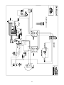
5. REFERENCE DRAWINGS .........................................................................................
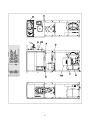
5.1 Auger and Front Door Drawings ............................................................................
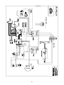
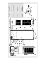
5.2 Air Cooled Parts & Wiring Diagram .......................................................................
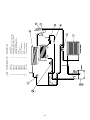
5.3 Water Cooled Parts & Wiring Diagram ..................................................................
5.4 General Parts List..................................................................................................
20
20
22
29
35
LIST OF ILLUSTRATIONS
FIGURE
TITLE
PAGE
1
Model Optima 212 Freezer .................................................................................... 1
2
Specifications ........................................................................................................ 1
3
Warning Label Locations ....................................................................................... 3
4
Leveling ................................................................................................................. 4
5
Space and Ventilation Requirements ..................................................................... 4
6
Electrical Plug ....................................................................................................... 4
7
Installing Tray and Cover ........................................................................................ 4
8
Power Cord Connection ......................................................................................... 5
9
Controls ................................................................................................................. 7
10
Mix Inlet Regulator ................................................................................................. 9
11
Clean Control ......................................................................................................... 9
12
Sanitizing Hopper .................................................................................................. 9
13
Draining Solution ................................................................................................... 9
14
Dispensing Product ...............................................................................................10
15
Removing Mix Inlet Regulator .................................................................................10
16
Draining Mix ..........................................................................................................11
17
Removing Front Door .............................................................................................11
18
Auger Shaft Removal .............................................................................................12
19
Removing "O" Ring ................................................................................................12
20
Cleaning Freezer Barrel .........................................................................................12
21
Exploded View of Auger .........................................................................................13
22
Mix Inlet Regulator .................................................................................................13
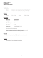
SECTION 1
DESCRIPTION AND SPECIFICATIONS
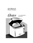
1.1 DESCRIPTION
The Stoelting Optima 212 floor model freezer is gravity
fed. The freezer is equipped with fully automatic controls
to provide a uniform product. The freezer is designed to
operate with almost any type of commercial shake mix
available. This manual is designed to assist qualified service personnel and operators in the installation, operation
and maintenance of the Stoelting Model Optima 212
freezer.
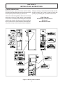
1.2 SPECIFICATIONS
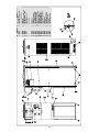
Figure 1. Model Optima 212 Freezer
&
5
< 6 /,67('
Figure 2. Specifications
1
MODEL OPTIMA 212
FLOOR MODEL
GRAVITY SHAKE FREEZER
DIMENSIONS:
Freezer:
Crated:
17.6" (45cm) wide x 28.6" (73cm) deep x 63.75" (162cm) high
19.5" (50cm) wide x 33" (84cm) deep x 40" (102cm) high
WEIGHT:
Freezer:
332 lbs. (150kg)
Crated:
427 lbs. (193kg)
ELECTRICAL:
Description
Optima 212-38
Voltage AC
1 PH 208/230
Total Run Amps
10.5
Drive Motor
3/4 HP
Compressor
10,760 BTUH (90°F - 0°F)
Use 20 amp HACR circuit breaker.
Automatic safeguard circuit built into electronic control - protects major
freezer components under abnormal operating conditions.
COOLING:
Air cooled requires minimum 3" (7.6cm) air clearance on back side.
No clearance needed on sides.
HOPPER:
6.25 Gallons (23.7 liters) refrigerated and insulated.
2
SECTION 2
INSTALLATION INSTRUCTIONS
2.1 SAFETY PRECAUTIONS
Do not attempt to operate the freezer until the safety
precautions and operating instructions in this manual are
read completely and are thoroughly understood.
If danger, warning or caution labels are needed, indicate
the part number, type of label, location of label, and
quantity required along with your address and mail to:
Take notice of all warning labels on the freezer. The labels
have been put there to help maintain a safe working
environment. The labels have been designed to withstand
washing and cleaning. All labels must remain legible for
the life of the freezer. Labels should be checked periodically to be sure they can be recognized as warning labels.
STOELTING, INC.
ATTENTION: Customer Service
502 Hwy. 67
Kiel, Wisconsin 53042
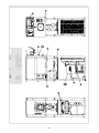
Figure 3. Warning Label Locations
3
2.2 SHIPMENT AND TRANSIT
The freezer has been assembled, operated and inspected
at the factory. Upon arrival at the final destination, the
complete freezer must be checked for any damage which
may have occurred during transit.
With the method of packaging used, the freezer should
arrive in excellent condition. THE CARRIER IS RESPONSIBLE FOR ALL DAMAGE IN TRANSIT, WHETHER
VISIBLE OR CONCEALED. Do not pay the freight bill until
the freezer has been checked for damage. Have the carrier
note any visible damage on the freight bill. If concealed
damage and/or shortage is found later, advise the carrier
within 10 days and request inspection. The customer must
place claim for damages and/or shortages in shipment
with the carrier. Stoelting, Inc. cannot make any claims
against the carrier.
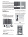
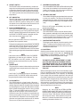
Figure 5. Space and Ventilation Requirements
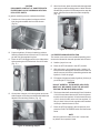
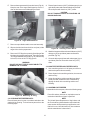
E. Connect the power cord. The plug is designed for 208
or 230 volt/20 amp duty. Check the nameplate on your
freezer for proper supply. The unit must be connected
to a properly grounded receptacle. The electrical cord
furnished as part of the freezer has a three prong
grounding type plug (Fig. 6). The use of an extension
cord is not recommended, if necessary use one with
a size 12 gauge or heavier with ground wire. Do not use
an adapter to get around grounding requirement.
2.3 FREEZER INSTALLATION
Installation of the freezer involves moving the freezer close
to its permanent location, removing all crating, setting in
place, assembling parts, and cleaning.
A.
Uncrate the freezer.
B.
Accurate leveling is necessary for correct drainage
of freezer barrel and to insure correct overrun. Place
a spirit level on top of the freezer at each corner to
check for level condition. If adjustment is necessary,
level the freezer by turning the caster in or out and
tighten the locknut. (Fig. 4).
Figure 6. Electrical Plug
CAUTION
DO NOT ALTER OR DEFORM PLUG IN ANY WAY!
F. Install the drip tray, drain tray, hopper cover and other
miscellaneous parts on the freezer. (Fig. 7).
Figure 4. Leveling
C. The freezer is equipped with an air cooled condenser
and requires correct ventilation. The front of the
freezer is the air intake and the back discharge. Both
front and back must have a minimum of 3" of
clearance. (Fig. 5).
CAUTION
FAILURE TO PROVIDE ADEQUATE VENTILATION
WILL VOID WARRANTY!
D. Place the OFF-ON switch in the OFF position. (Fig.10).
Figure 7. Installing Tray and Cover
4
2.4 INSTALLING PERMANENT WIRING
If permanent wiring is required by local codes, the following procedure must be performed.
WARNING
DISCONNECT FREEZER FROM THE SOURCE
OF ELECTRICAL SUPPLY BEFORE SERVICING.
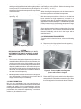
A. Remove the left side panel and electrical box cover.
B. Disconnect the wires from the terminal
block. Disconnect the green ground wire from the
grounding stud. (Fig. 8).
Figure 8. Power Cord Connection
C. Remove the power cord.
D. Install permanent wiring according to local code.
E. Replace the electrical box cover and left side panel.
5
6
SECTION 3
INITIAL SETUP AND OPERATION
G. Do not operate under unsafe operating conditions. Never operate the freezer if unusual or excessive noise or vibration occurs.
3.1 OPERATOR'S SAFETY PRECAUTIONS
SAFE OPERATION IS NO ACCIDENT; Observe these
rules:
A. Know the freezer. Read and understand the
Operating Instructions.
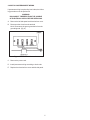
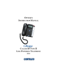
3.2 OPERATING CONTROLS AND INDICATORS
Before operating the freezer, it is required that the
operator know the function of each operating control.
Refer to Figure 9 for the location of the operating
controls on the freezer. For the information regarding
flashing indicator lights, refer to the troubleshooting
section.
B. Notice all warning labels on the freezer.
C. Wear proper clothing. Avoid loose fitting garments, and remove watches, rings or jewelry which
could cause a serious accident.
D. Maintain a clean work area. Avoid accidents by
cleaning up the area and keeping it clean.
WARNING
THE OFF-ON SWITCH MUST BE PLACED IN THE OFF
POSITION WHEN DISASSEMBLING FOR CLEANING
OR SERVICING. THE FREEZER MUST BE DISCONNECTED FROM ELECTRICAL SUPPLY BEFORE REMOVING ANY ACCESS PANEL.
E. Stay alert at all times. Know which switch, push
button or control you are about to use and what
effect it is going to have.
F. Disconnect electrical cord for maintenance.
Never attempt to repair or perform maintenance on
the freezer until the main electrical power has been
disconnected.
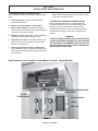
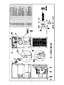
High Pressure Cutout Switch Located Back of Freezer (Some Models)
DISPENSE RATE
ADJUSTMENT
HOLD READY
SWITCH
È
È
Ç
Ê
OFF-ON
POWER SWITCH
CONSISTENCY/TEMPERATURE
ADJUSTMENT
Å
Å
Å
Figure 9. Controls
7
PUSH TO FREEZE
CLEAN
MIX LOW
A. SPIGOT SWITCH
The SPIGOT switch will automatically actuate the
auger drive and refrigeration systems when the spigot
is opened to dispense product. When the spigot is
closed, the drive motor and compressor will remain
"on" until the product in the barrel reaches the proper
temperature.
F. DRIVE MOTOR OVERLOAD
The internal DRIVE MOTOR OVERLOAD will trip if the
drive motor is overloaded. It will reset after approximately 10-12 minutes. If the drive motor continues to
trip, refer to Troubleshooting (Sec. 4).
G. RED MIX LOW LIGHT
The red MIX LOW light is designed to alert the operator
to a low mix condition. The light will illuminate with
approximately one gallon of mix in the hopper. When
the MIX LOW light is illuminated, refill hopper immediately.
NOTE
Failure to refill hopper immediately may result in
operational problems.
B. OFF-ON SWITCH
The OFF-ON switch is a two position toggle switch
used to supply power to the control circuit. When the
switch is in the OFF position, nothing will run. When
the switch is in the ON position the freezer will be in
the idle mode until a switch is activated.
C. PUSH TO FREEZE SWITCH
The PUSH TO FREEZE switch is a "snap" switch used
to start the freezing cycle. During initial freeze down,
the OFF-ON switch is placed in the ON position. Then
the PUSH TO FREEZE switch is pressed until the
drive motor and compressor come "ON".
H. HOLD READY SWITCH
The HOLD READY switch is a push button switch.
When pushed in and held for 5 seconds, the hold ready
mode will be activated. The product will remain ready
to serve and the freezer will not go to idle. To return to
normal operation push and hold for 5 seconds.
NOTE
After the gearmotor starts, there is a 3 second delay before the compressor starts.
I.
During the normal operation, the red PUSH TO FREEZE
switch light will illuminate after the freezer has been
idle for the preset cycles. Before drawing product,
press the PUSH TO FREEZE switch if it is illuminated.
Wait until the green light is illuminated before dispensing.
DISPENSE RATE ADJUSTER
The dispense rate adjuster limits the opening of the
spigot. To adjust product dispense rate, turn the
adjusting knob clockwise for slower flow and counterclockwise for faster flow.
3.3 SANITIZING
Sanitizing must be done after the freezer is cleaned and
just before the hopper is filled with mix. Sanitizing the
night before is not effective. However, you should
always clean the freezer and parts after using it.
NOTE
If the freezer shuts off and the PUSH TO FREEZE
light flashes, you have an error condition. Turn the
OFF-ON swtich to the OFF position, correct the
problem and turn the freezer back on. (See Troubleshooting.)
WARNING
THE UNITED STATES DEPARTMENT OF AGRICULTURE AND THE FOOD AND DRUG ADMINISTRATION REQUIRE THAT ALL CLEANING AND
SANITIZING SOLUTIONS USED WITH FOOD
PROCESSING EQUIPMENT BE CERTIFIED FOR
THIS USE.
D. GREEN LIGHT
The green light is used to indicate that the product has
reached the proper temperature and is ready to be
dispensed.
When sanitizing the freezer, refer to local sanitary regulations for applicable codes and recommended sanitizing
products and procedures. The frequency of sanitizing
must comply with local health regulations. Mix sanitizer
according to manufacturer's instructions to provide a 100
parts per million strength solution. Mix sanitizer in quantities of no less than 2 gallons (7.5 liters) of 120°F water.
Allow sanitizer to contact the surfaces to be sanitized for
5 minutes. Any sanitizer must be used only in accordance
with the manufacturer's instructions.
NOTE
If the PUSH TO FREEZE red light is illuminated,
push the PUSH TO FREEZE switch and wait until
the green light illuminates before dispensing.
E. CLEAN SWITCH
The CLEAN switch is a "snap" switch. When the
switch is pushed the refrigeration system will be OFF
and the auger will rotate for cleaning. When the switch
is pushed again, the auger will stop and the CLEAN
light will flash indicating the freezer is in the CLEAN
mode. To exit the CLEAN mode turn the OFF-ON
switch to the OFF position. If the freezer is left in
CLEAN for more than 30 minutes or is pushed three
times in ten seconds, it will go in error. To reset place
the CLEAN-OFF-ON switch in the ON position and
allow the error light to flash a minimum of 10 minutes.
Then turn to off, wait 5 seconds and turn on.
NOTE
Stoelting, Inc. has found that STERA-SHEEN
GREEN LABEL SANITIZER AND CLEANER does
an effective job of properly sanitizing and cleaning a
soft serve freezer. We therefore include a sample
with each new freezer. Other products may be as
effective. For further information refer to cleaning and
sanitizing information Section 3.13.
8
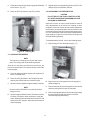
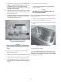
E. After five minutes, place a bucket under the spigot and
open spigot to drain sanitizing solution. When solution
has drained, press the CLEAN snap switch to stop the
auger. Allow the freezer barrel to drain completely
(Fig. 13).
CAUTION
PROLONGED CONTACT OF SANITIZER WITH
FREEZER MAY CAUSE CORROSION OF STAINLESS STEEL PARTS.
In general, sanitizing may be conducted as follows:
A. Push the mix inlet regulator into hopper with air
inlet (long) tube toward the front of the freezer
(Fig.10).
Figure 13. Draining Solution
Figure 10. Mix Inlet Regulator
B. Prepare 4 gallons (15 liters) of sanitizing solution
following manufacturer's instructions. Pour into hopper with mix inlet regulator in place.
3.4 FREEZE DOWN AND OPERATION
This section covers the recommended operating procedures to be followed for the safe operation of the freezer.
C. Place the OFF-ON toggle switch in the ON position
while pressing the CLEAN switch. Check for leaks.
(Fig. 11.)
A. Sanitize just prior to use.
B. Place the OFF-ON switch in the OFF position.
C. With spigot open, pour approximately 1 gallon (3.8
liters) of mix into the hopper. Allow the mix to flush out
about 8 ounces (0.23 liters) of sanitizing solution and
liquid mix. Close the spigot.
D. Fill hopper with approximately 5 gallons (19 liters) of
pre-chilled (40°F or 4°C) mix.
CAUTION
DO NOT OVERFILL THE HOPPER. MIX LEVEL
MUST NOT BE HIGHER THAN THE AIR INLET
TUBE ON THE MIX INLET REGULATOR.
Figure 11. Clean Control
E. The freezer barrel will automatically fill until it is about
1/2 full. If freezer barrel does not fill, check for obstruction in the mix inlet regulator. If freezer barrel fills over
1/2 full, check for leaks at the mix inlet regulator "O"
Ring or check if the mix inlet regulator was installed
correctly or that the freezer is level.
D. Clean sides of hopper, mix inlet regulator and under
side of hopper cover using a sanitized soft bristle brush
dipped in the sanitizing solution. (Fig. 12).
F. Place the OFF-ON switch in the ON position, then
press the PUSH TO FREEZE switch until the freezer
starts.
NOTE
After the gearmotor starts, there is a 3 second delay before the compessor starts.
Figure 12. Sanitizing Hopper
9
G. After about 7 to 10 minutes the freezer will shut OFF
and the green light will illuminate indicating the product
is ready to serve. Freeze down time may be longer for
some mixes. High ambient temperatures may extend
freeze down time.
Proper product serving temperature varies from one
manufacturer's mix to another. Shake mixes range from
24° to 28°F (-4° to -2°C).
When checking the temperature, stir the thermometer in
the frozen product to read the true temperature.
H. For normal dispensing, move the spigot handle fully
open. (Fig. 14).
Mix does not improve with age. Old mix, or mix that has
been stored at too high temperature, can result in a
finished product that is less than satisfactory from the
appearance and taste standpoint. To retard bacteria growth
in dairy based mixes, the best storage temperature range
is between 36° to 40°F (2.2° to 4.4°C).
Some products tend to foam more than others. If excess
foam should occur, skim off with a sanitized utensil and
discard. Periodically, stir the mix in the hopper with a
sanitized utensil.
3.6 REMOVING MIX FROM FREEZER
To remove the mix from the freezer, refer to the following
steps:
A. Remove the mix inlet regulator from the hopper by
pulling straight up (Fig. 15).
Figure 14. Dispensing Product
CAUTION
REFRIGERATION IS AUTOMATICALLY ACTIVATED WHEN THE SPIGOT IS OPENED. CLOSE
THE SPIGOT COMPLETELY AFTER DISPENSING.
I.
J.
The freezer is designed to dispense the product at a
reasonable draw rate. If the freezer is overdrawn, the
result is a very thin product. If this should occur, allow
the freezer to run for approximately 30 seconds before
dispensing additional product. After a while the operator will sense or feel when the freezer is beginning to
fall behind, and will slow down on the rate of draw so
as not to exceed the capacity.
Figure 15. Removing Mix Inlet Regulator
(Shown with no mix in hopper)
Do not operate the freezer when the MIX LOW light is
on or with less than 1-3/4 inches (4.4 cm) of mix in the
hopper. Refill the hopper immediately.
B. Place the OFF-ON rocker switch in the ON position
and push the CLEAN switch to rotate the auger. Allow
the mix to agitate in freezer barrel about 5 minutes.
3.5 MIX INFORMATION
Mix can vary considerably from one manufacturer to
another. Differences in the amount of butter-fat content and
quantity and quality of other ingredients have a direct
bearing on the finished frozen product. A change in freezer
performance that cannot be explained by a technical
roblem may be related to the mix.
10
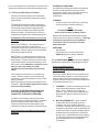
C. Empty the freezer by opening the spigot and draining
into a bucket. (Fig. 16).
E. Repeat Steps A through D using a warm (120°F) mild
detergent (Joy or equivalent) solution.
D. Place the OFF-ON switch in the OFF position.
3.8 DISASSEMBLY OF FREEZER PARTS
CAUTION
PLACE THE OFF-ON TOGGLE SWITCH IN THE
OFF POSITION BEFORE DISASSEMBLING FOR
CLEANING OR SERVICING.
Inspection for worn or broken parts should be made at
every disassembly of the freezer for cleaning or other
purposes. All worn or broken parts should be replaced to
ensure safety to both the operator and the customer and
to maintain good freezer performance and a quality product. Two normal wear areas are the auger flights and front
auger support. Frequency of cleaning must comply with
the local health regulations.
To disassemble the freezer, refer to the following steps:
A. Remove hopper cover and drain tray (Fig. 17).
Figure 16. Draining Mix
3.7 CLEANING THE FREEZER
NOTE
The frequency of cleaning the freezer and freezer
parts must comply with local health regulations.
After the mix has been removed from the freezer, the
freezer must be cleaned. To clean the freezer, refer to the
following steps:
A. Close the spigot and fill the hopper with 4 gallons (15
liters) of cold tap water.
Figure 17. Removing Front Door
B. Place the OFF-ON switch in the ON position while
pushing the CLEAN switch to rotate the auger.
B. Remove the mix inlet regulator from the hopper by
pulling straight up.
C. Allow the water to agitate for approximately 5 minutes.
C. Remove the front door by turning off the circular knobs
and then pulling the front door off the studs.
NOTE
If freezer is left in CLEAN for more than 30 minutes,
it will go to error.
D. Remove the spigot body from the front door by pushing
the spigot body through the bottom of the door.
Remove auger support bushing.
D. Open the spigot to drain the water. Remember to place
a bucket or container under the spigot to catch the
water. When the water has drained, turn the OFF-ON
switch to the OFF position. Allow the freezer barrel to
drain completely.
11
A. Place all parts in warm (120°F) mild detergent (Joy or
equivalent) water and clean with brushes provided.
Rinse all parts with clean hot (135°F) water.
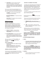
E. Remove the auger assembly from the freezer (Fig.18).
Keep the rear of the auger shaft tipped up once it is
clear of the freezer to avoid dropping rear seal.
CAUTION
DO NOT DAMAGE PARTS BY DROPPING OR
ROUGH HANDLING.
Figure 18. Auger Shaft Removal
F. Remove scaper blades and the rear seal assembly.
G. Wipe socket lubricant from the drive end (rear) of the
auger with a cloth or paper towel.
Figure 20. Cleaning Freezer Barrel
B. Wash the hopper and freezer barrel with warm (120°F)
detergent (Joy or equivalent) water and brushes
provided. (Fig. 20).
H. Remove all "O" Rings from parts by first wiping off the
lubricant using a clean paper towel. Then squeeze the
"O" Ring upward with a dry cloth (Fig. 19). When a loop
is formed, roll out of the "O" Ring groove.
C. Clean the drip tray and insert with a detergent (Joy or
equivalent) solution. Rinse with clean hot (135°F)
water.
WARNING
DO NOT USE ANY TYPE OF SHARP OBJECT TO
REMOVE THE "O" RINGS.
3.10 SANITIZE FREEZER AND FREEZER PARTS
A. Use a sanitizing solution of 100 parts per million to
sanitize the parts before assembly.
B. Place all parts in the sanitizing solution, then remove
and let air dry.
C. Using this sanitizing solution and the large barrel
brush provided, sanitize the rear of the barrel by
dipping the brush in the sanitizing solution and
brushing.
3.11 ASSEMBLY OF FREEZER
To assemble the freezer parts, refer to the following steps:
NOTE
Petro-Gel sanitary lubricant or equivalent must be
used when lubrication of parts is specified.
Figure 19. Removing "O" Ring
3.9 CLEANING THE FREEZER PARTS
Place all loose parts in a pan or container and take to the
wash sink for cleaning. To clean freezer parts refer to the
following steps:
NOTE
The United States Department of Agriculture and
the Food and Drug Administration require that lubricants used on food processing equipment be certified for this use. Use lubricants only in accordance
with the manufacturer's instructions.
12
A. Assemble all "O" Rings onto parts dry, without lubrication. Then apply a thin film of sanitary lubrication to
exposed surfaces of the "O" Rings. Also apply
a thin film of sanitary lubricant inside and outside of the
front auger support bushing.
H. Install the front door on the freezer.
I.
Install the circular knobs on the freezer studs and
tighten hand tight.
CAUTION
TIGHTEN THE CIRCULAR KNOBS EVENLY. DO
NOT OVERTIGHTEN KNOBS.
B. Assemble the rear seal onto the auger with the large
end to the rear. Be sure the "O" Ring is in place before
installing the rear seal.
C. Lubricate the auger drive (rear) with a small amount of
white socket lubricant. A container of socket lubricant is shipped with the freezer.
Look for the proper seal between the freezer barrel, "O"
Ring, and front door.
J.
Install the mix inlet regulator into the freezer with the
air tube to the front of the freezer (Fig. 22).
K. Install hopper cover and drain tray and drip tray with
insert.
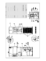
Figure 21. Exploded View of Auger
(Front Door and Related Parts)
CAUTION
DO NOT PLACE THE MIX INLET REGULATOR
INTO THE HOPPER BEFORE INSTALLING THE
AUGER.
Figure 22. Mix Inlet Regulator
3.12 ROUTINE CLEANING
D. Install the two plastic flights onto the auger and
insert into freezer barrel.
To remove spilled or dried mix from the freezer exterior,
simply wash in the direction of the finish with warm soapy
water and wipe dry. Do not use highly abrasive materials
as they will mar the finish.
E. Rotate slowly until the auger engages the drive shaft.
F. Install the auger support bushing into the front door.
G. Install the spigot body with "O" Rings into the front
door from bottom. Push straight up until the spigot is
in place.
13
It is recommended that a maintenance schedule be followed to keep the freezer clean and operating properly.
CLEANING vs. SANITIZING
It is important to distinguish between cleaning and
sanitizing. Although these terms may sound
synonymous, they are not. BOTH are required for
adequate food safety and proper machine
maintenance.
A. Cleaning and Sanitizing Information
Soft serve freezers require special consideration
when it comes to food safety and proper cleaning
and sanitizing.
CLEANING
·
Is the removal of soil materials from a surface.
·
Is a prerequisite for effective sanitizing.
The following information has been compiled by
Purdy Products Company, makers of Stera-Sheen
Green Label Cleaner/Sanitizer and specifically
covers issues for cleaning and sanitizing frozen
dessert machines. This information is meant to
supplement a comprehensive food safety program.
NOTE
An UNCLEAN surface will harbor
bacteria that can defy sanitizing efforts.
Bacteria can develop and resist sanitizing efforts
within a layer of soil material (milkstone). Thorough
cleaning procedures that involve milkstone
removal are critical for operators of frozen
dessert machines.
Soil Materials Associated with Frozen Dessert
Machines
MILKFAT/BUTTERFAT – As components of icecream/frozen custard mix, these soils will
accumulate on the interior surfaces of the machine
and its parts. Fats are difficult to remove and help
attribute to milkstone build-up.
SANITIZING
·
Kills bacteria.
·
Can be effective on clean surfaces only.
·
DOES NOT clean or remove milkstone.
MILKSTONE – Is a white/gray film that forms on
equipment and utensils that come in contact with
dairy products. These films will accumulate slowly
on surfaces because of ineffective cleaning, use of
hard water, or both. Milkstone is usually a porous
deposit, which will harbor microbial
contaminants and eventually defy sanitizing
efforts.
NOTE
Using a SANTITIZER on an unclean surface will not
guarantee a clean and safe frozen dessert machine.
Proper Daily Maintenance:
The Only Way to Assure Food Safety and
Product Quality
Once milkstone has formed, it is very difficult to
remove. Without using the correct product and
procedure, it is nearly impossible to remove a thick
layer of milkstone.
(NOTE: general-purpose cleaners DO NOT remove
milkstone.) This can lead to high bacteria counts
and a food safety dilemma.
Proper daily maintenance can involve a wide variety
of products and procedures. Overall, the products
and procedures fall into three separate categories.
(Please note that this is a brief overview intended for
informational purposes only.)
1.
CLEANING – This involves draining mix from the
freezer barrel and rinsing the machine with
water. Next, a cleaner is run through the
machine. Then, the machine is disassembled
and removable parts are taken to the sink for
cleaning.
2.
MILKSTONE REMOVAL – Since almost all
cleaners do not have the ability to remove
milkstone, the use of a delimer becomes
necessary. Although this procedure may not be
needed on a daily basis, it will usually follow the
cleaning procedure. It requires letting a delimer
solution soak in the machine for an extended
period of time. Individual parts are also soaked
in a deliming solution for an extended period of
time (more about delimers in Additional
Information).
IT IS BEST TO CONTROL MILKSTONE ON A
DAILY BASIS BEFORE IT CAN BECOME A
SIGNIFICANT FOOD SAFETY PROBLEM.
In addition to food safety, milkstone can cause
premature wear to machine parts which can add to
costs for replacement parts or possibly more
expensive repairs if worn machine parts are not
replaced once they have become excessively worn.
Important Differences Between Cleaning and
Sanitizing
14
3.
THE USE OF CHLORINE TEST STRIPS
SANITIZING – After the machine has been
cleaned and contains no milkstone, the
machine is reassembled. Then a FDA-approved
sanitizing solution is run through the machine to
kill bacteria. The machine is then ready for food
preparation.
“Test strips” are used to determine concentrations of
active chlorine in sanitizing solutions. To use the
strips, tear off a small portion and submerge it into
the sanitizing solution. Then, compare the color
change to the color key on the side of the test strip
dispenser to determine the approximate chlorine
concentration.
As a recommended cleaner and sanitizer for your
frozen dessert machine, STERA-SHEEN has proven
to be one of the best daily maintenance products for:
The ideal concentration of chlorine needs to be 100
ppm (as stated by the FDA).
·
CLEANING – Thorough removal of all solids
including butterfat and milk fat.
·
MILKSTONE REMOVAL – Complete removal of
milkstone.
NOTE
Follow the directions on the container for proper
concentration.
·
SANITIZING – FDA-approved no rinse sanitizer
for food contact surfaces.
There are two main factors that contribute to falling
chlorine concentrations in a sanitizing solution.
Additional Information
THE USE OF DELIMERS
A delimer is a strong acid that has the ability to
dissolve milkstone. This type of chemical may
become necessary once high levels of milkstone
have developed. While these products are very
effective for removing HIGH levels of milkstone, they
are not ideal for two reasons:
1.
2.
1.
PRODUCT USE – As the chlorine in the
solution is being used, chlorine concentrations
fall.
2.
TIME – As time passes, small amounts of
chlorine “evaporate” from the solution. (That is
why you can smell it.)
Sanitizing solutions should not be allowed to fall
below 100 ppm chlorine. New solutions should be
mixed once old solutions become ineffective.
PRODUCT SAFETY – Strong acids are
dangerous chemicals and handling them
requires safety
WARNING
NEVER ATTEMPT TO REPAIR OR PERFORM
MAINTENANCE ON FREEZER UNTIL THE MAIN
ELECTRICAL POWER HAS BEEN DISCONNECTED.
MACHINE DAMAGE – Strong acids will attack
metal and rubber causing premature wear of
parts. The use of a delimer needs to be closely
monitored to avoid damage to machine surfaces
and parts.
3.13 PREVENTIVE MAINTENANCE
A. DAILY
With proper daily use of STERA-SHEEN or it’s
equivalent, there is no need for the use of a
DELIMER.
1.
DO NOT USE BLEACH
·
BLEACH HAS ABSOLUTELY NO CLEANING
PROPERTIES.
·
BLEACH IS CORROSIVE. It can and will
damage components of the machine causing
premature wear and metal corrosion.
The exterior should be kept clean at all times to
preserve the lustre of the stainless steel. A mild
alkaline cleaner is recommended. Use a soft
cloth or sponge to apply the cleaner.
CAUTION
DO NOT USE ACID CLEANERS, STRONG CAUSTIC COMPOUNDS OR ABRASIVE MATERIALS TO
CLEAN ANY PART OF THE FREEZER EXTERIOR
OR PLASTIC PARTS.
GENERAL PURPOSE CLEANERS
B. WEEKLY
General purpose cleaners do not have the ability to
remove milkstone. Milkstone will become a problem
if not remedied with additional products and
procedures.
1.
15
Check "O" Rings and rear seal for excessive
wear and replace if necessary.
2.
Remove the drip tray by gently lifting up to
disengage from the support and pulling out.
Clean behind the drip tray and front of the
freezer with a soap solution.
C. MONTHLY
CAUTION
THE FREEZER HAS AN AIR COOLED CONDENSER AND MUST HAVE PROPER AIR CIRCULATION. MAINTAIN 3" OF CLEARANCE AT ALL
LOUVERED PANELS. FAILURE TO CLEAN THE
CONDENSER FILTER ON A REGULAR BASIS MAY
RESULT IN SERIOUS FREEZER DAMAGE AND
COULD VOID FREEZER WARRANTY.
1. Remove the condenser filter by lifting up and pulling
bottom out and down. Then clean with warm soapy
water. Rinse in clean water and shake dry, taking
care not to damage the filter in any way.
2. Replace the condenser filter.
D. SEMI-ANNUALLY
1. Check drive belt for proper tension. Push belt in with
one finger, belt should deflect about 3/8".
2. Lubricate condenser fan motor with S.A.E. 20 weight
oil. Three to six drops is required.
CAUTION
DO NOT OVER LUBRICATE; RESULTING DAMAGE COULD CAUSE MOTOR FAILURE.
3.14 EXTENDED STORAGE
Refer to the following steps for storage of the freezer over
any long period of shutdown time:
A. Turn the OFF-ON switch to the OFF position.
B. Disconnect (unplug) from the electrical supply source.
C. Clean thoroughly with a warm detergent all parts that
come in contact with the mix. Rinse in clean water and
dry parts. Do not sanitize.
NOTE
Do not let the cleaning solution stand in the hopper
or in the freezer barrel during the shutdown period.
D. Remove, disassemble and clean the front door, mix
inlet regulator and auger parts. Place the auger flights
and the front auger support bushing in a plastic bag
with a moist paper towel to prevent them from becoming brittle.
16
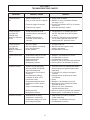
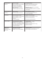
SECTION 4
TROUBLESHOOTING CHARTS
PROBLEM
Freezer does not
run.
POSSIBLE CAUSE
REMEDY
1. Power to freezer is off.
2. Fuse or circuit if blown or tripped.
4. Front door not in place.
1. Supply power to freezer.
2. Replace or reset. (If condition continues,
see notes 1 or 2).
3. Turn OFF-ON switch to OFF for 15 minutes,
then restart.
4. Assemble front door in place.
Freezer does not
run, PUSH TO
FREEZE light
flashes in sequence
of four.
1. Freezer has been left in the
CLEAN mode for more than 20
minutes.
2. CLEAN switch has been
activated 3 times within 10
seconds.
1. Let light flash for 10 minutes, then place
the OFF-ON switch to the OFF position
to reset.
2. Leave OFF-ON switch in the ON position
for 10 minutes, then place the OFF-On
switch to the OFF position to reset.
Freezer does not
run, PUSH TO
FREEZE light
flashes in sequence
of five.
1. No mix in hopper.
2. Mix inlet regulator not allowing
mix to flow into barrel.
3. Sensor problem.
1. Fill hopper with mix.
2. Remove mix inlet regulator, clean,
sanitize, and replace.
3. Call distributor for service.
Freezer will not shut
off.
1. Temperature setting is too cold.
2. Push to freeze switch failure.
3. Spigot switch failure.
4. Reduced air flow.
5. Refrigeration problem.
1. Readjust. Call distributor for service.
2. Call distributor for service.
3. Call distributor for service.
4. Check for proper air flow thru the condenser
5. Check system. Call distributor for service.
Product is too thin.
1. Product is being dispensed
when the PUSH TO FREEZE
light is illuminated red.
2. No vent space for free flow of
cooling air.
3. Air temperature entering
condenser is above 100°F.
4. Condenser is dirty.
5. Temperaturesetting too warm.
6. Stabilizers in mix are broken
down.
7. Auger is assembled wrong.
8. Reduced air flow.
9. Refrigeration problem.
1. Press the PUSH TO FREEZE push button.
Wait until the green light illuminates before
dispensing.
2. A minimum of 3 inches of vent space
required.
3. Change location or direct hot air away
from freezer.
4. Clean.
5. Readjust. Call distributor for service.
6. Remove mix, clean, sanitize and freeze
down with fresh mix.
7. Remove mix, clean, reassemble,
sanitize and freeze down.
8. Check for proper air flow thru the condenser.
9. Check system. Call distributor for service.
1. Small portions are being
dispensed in a short time.
2. Temperature setting is too cold.
3. Line voltage fluctuating.
1. Allow freezer to sit idle for 5 minutes
before dispensing.
2. Readjust. Call distributor for service.
3. Call distributor for service.
3. Freeze-up (auger will not turn).
Product is too thick.
17
1. No mix in hopper.
2. Mix inlet regulator tube is plugged.
3. Special mix inlet regulator
needed for mix being used.
4. Drive motor overload tripped.
5. Drive belt failure.
6. Freeze-up. (Auger will not turn.)
1. Fill hopper with mix.
2. Unplug, using small sanitized brush.
3. Order special mix inlet regulator.
Drive belt slipping or
squealing.
1. Worn drive belt.
2. Freeze-up (Auger will not turn).
1. Call distributor for service.
2. Turn OFF-ON switch to OFF for 15
minutes, then restart.
Low overrun.
1. Mix inlet regulator missing.
2. Mix inlet regulator "O"ring missing
3. Mix inlet regulator air tube
blocked.
4. Product breakdown.
1. Replace mix inlet regulator.
2. Replace mix inlet regulator "O" ring.
3. Clean with sanitized brush.
Front door leaks
1. Front door knobs are loose.
2. Spigot parts are not lubricated.
3. Chipped or worn spigot "O" rings.
4. "O" rings or spigot installed wrong.
5. Inner spigot hole in front door
nicked or scratched.
1. Tighten knobs.
2. Assemble & lube correctly.
3. Replace "O" rings.
4. Remove spigot and check "O" ring.
5. Replace front door.
Hopper will not
maintain mix
temperature below
45°F (7°C)
1. EPR valve needs adjustment.
2. Refrigeration problem.
3. Hopper cover not fitted properly.
1. Adjust EPR valve.
2. Check system. Call distributor for service.
3. Check hopper cover for proper fit.
Product does not
dispense.
18
4. Automatic reset. Wait 15 to 30 minutes.
6. Replace drive belt.
7. Turn OFF-ON switch to OFF for 15 minutes,
then restart.
4. Fill freezer with fresh product.
ERROR CODES
Malfunction
Indicator
01
02
03
04
05
06
07
ERR
ERR
ERR
ERR
ERR
ERR
ERR
Program Board
Power Board
Low Torque Error
Clean Error
Barrel Sensor
Hopper Sensor
Drive Motor
To Clear Error Modes
Clean Error 04: Allow freezer to remain on (light blinking) with the power switch in the
ON position for ten (10) minutes minimum. Next, place the power switch in the
OFFposition for five (5) seconds minimum, then place the power switch in the ON
position to restart freezer. All other errors turn power switch off for five (5) seconds
minimum. Then place the power switch in the ON position to restart freezer.
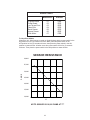
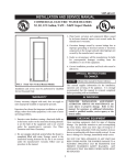
SENSOR RESISTANCE
60,000
55,000
OHMS
50,000
45,000
40,000
35,000
30,000
12
16
20
24
28
32
ºF
NOTE: SENSOR IS 10,000 OHMS AT 77°
19
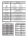
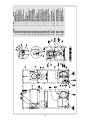
SPECIFICATIONS
MODEL O212
DIMENSIONS
Air Cooled
FREEZER
WITH CRATE
Depth
Width
Height
17.6" (47.7cm)
63.75" (161.9cm)
28.625 (72.7cm)
WEIGHT
25" (63.5cm)
66" (167.7cm)
51" (129.5cm)
FREEZER
332 lbs. (150kg)
WITH CRATE
427 lbs. (193kg)
ELECTRICAL
1 phase, 208/230 AC
Cord connected 10.5 running amps
20 amp HACR circuit breaker.
COMPRESSOR
One Compressor, 10760 BTUH, 90°F - 0°F
DRIVE MOTOR
3/4 H.P.
COOLING
Air or water cooled available.
HOPPER VOLUME
25 Quart (23.66 liters)
BARREL VOLUME
8 Quart (7.57 liters)
FREEZING CAPACITY *
16-20 Gallons per hour (70-80°F)
73-91 Liter per hour (21.1 - 26.7°C)
* Proper operating conditions
CONTROL SETTINGS
REFRIGERATION SPECIFICATIONS
SET
PUSHBUTTON
1
2
3
4
DISPLAY
SEC TM
TM STB
SEC TM STB
AMP CRS
O212-38
3
10
48
3.5
5
6
7
8
9
SRV
STB
LKG STB
MTR
HPR
28
32
5
0.5
45
S u p er H eat o u t o f
Evaporator
2-12°F
(-16.7 to -11.1°C)
At Capacity
Suction Pressure
29-31 psig
At Capacity
10
CYCLE
LK G
32
8
Head Pressure
MODEL
Refrigerant
Charge
Hopper Pressure
Continuous research leads to on-going inprovements.
Spec's subject to change.
20
O212
R-404A
35 oz. A/C
(992.3 grams)
240-250 lbs. A/C
69-71 psig
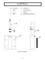
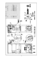
SECTION 5
REFERENCE DRAWINGS
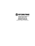
ITEM
1
2
3
4
5
6
STOELTING PN
QTY
DESCRIPTION
336530-SV
625314
3177738
624614
508135
1
1
1
1
2
.001
Front Door - Shake
Ring-O, 6" OD x 1/4 CS
Door Pin
Spigot Body
Ring-O, 3/4 IDX 1.0 ODX 1/8 CS
Lubricant, Petro-Gel, 4 Oz. Tubes
FRONT DOOR ASSEMBLY
21
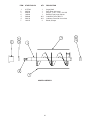
ITEM
1
2
3
4
5
6
7
STOELTING PN
QTY
DESCRIPTION
4177749
666786
624678
149002
508048
508135
162155
1
1
1
1
.001
.001
2
Auger Shaft
Seal, Rear with Insert
Ring-O, 1-1/2 x 1-1/8 x 3/16 CS
Bearing Front Auger Celcon
Lubricant Fel-Pro #51171
Lubricant, Petro-Gel 4 oz. tubes
Blade, Scraper
AUGER ASSEMBLY
22
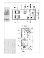
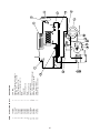
23
24
25
26
-SV
DS
ASSY
27
A/C
28
29
762978
4177709
231105
762443
458003
342004
284083
282032
342020
282033
2171962
1
2
3
4
5
6
7
8
9
10
11
1
1
1
1
1
1
1
1
1
1
1
STOELTING PN QTY
ITEM
Valve EPR
Hopper & Evaporator Assembly
Capillary Tube, .072 x .026 20'
Valve, Expansion 1 Ton
Indicator, Sight Glass 1/4
Drier
Condenser
1 PH Compressor
Drier
3 PH Compressor
Sensor Assembly
DESCRIPTION
30
31
32
-SV
DS
ASSY
33
34
35
762978
4177709
231105
762443
458003
342004
284068
282032
342020
282033
2171962
450061
264238
763181
718710
1
2
3
4
5
6
7
8
9
10
11
12
13
14
15
1
1
1
1
1
1
1
1
1
1
1
34'
4
1
1
STOELTING PN QTY
ITEM
Valve EPR
Hopper & Evaporator Assembly
Capillary Tube, .072 x .026 20'
Valve, Expansion 1 Ton
Indicator, Sight Glass 1/4
Drier
Condenser
1 PH Compressor
Drier
3 PH Compressor
Sensor Assembly
Hose, Water 1/2 250 PSI Goodyear
Clamp, Hose #87/16 - 29/32
Valve, Water 3/8 NPT
Switch High Limit Control
DESCRIPTION
36
WARRANTY
SOFT SERVE / SHAKE FREEZERS
1. Scope:
Stoelting, LLC warrants to the first user (the “Buyer”) that the freezer cylinders, hoppers, compressors, drive motors,
speed reducers, auger and auger flights of Stoelting soft serve / shake freezers will be free from defects in materials
and workmanship under normal use and proper maintenance appearing within five (5) years, and that all other
components of such equipment manufactured by Stoelting will be free from defects in material and workmanship
under normal use and proper maintenance appearing within twelve (12) months after the date that such equipment is
originally installed.
2. Disclaimer of Other Warranties:
THIS WARRANTY IS EXCLUSIVE; AND STOELTING HEREBY DISCLAIMSANY IMPLIED WARRANTY OF MERCHANTABILITY OR FITNESS FOR PARTICULAR PURPOSE.
3. Remedies:
Stoelting’s sole obligations, and Buyer’s sole remedies, for any breach of this warranty shall be the repair or (at
Stoelting’s option) replacement of the affected component at Stoelting’s plant in Kiel, Wisconsin, or (again, at
Stoelting’s option) refund of the purchase price of the affected equipment, and, during the first twelve (12) months of
the warranty period, deinstallation/reinstallation of the affected component from/into the equipment. Those obligations/remedies are subject to the conditions that Buyer (a) signs and returns to Stoelting, upon installation, the
Checklist/Warranty Registration Card for the affected equipment, (b) gives Stoelting prompt written notice of any
claimed breach of warranty within the applicable warranty period, and (c) delivers the affected equipment to Stoelting
or its designated service location, in its original packaging/crating, also within that period. Buyer shall bear the cost
and risk of shipping to and from Stoelting’s plant or designated service location.
4. Exclusions and Limitations:
This warranty does not extend to parts, sometimes called “wear parts”, which are generally expected to deteriorate
and to require replacement as equipment is used, including as examples but not intended to be limited to o-rings,
auger seals, auger support bushings and drive belts. All such parts are sold
AS IS.
Further, Stoelting shall not be responsible to provide any remedy under this warranty with respect to any component
that fails by reason of negligence, abnormal use, misuse or abuse, use with parts or equipment not manufactured or
supplied by Stoelting, or damage in transit.
THE REMEDIES SET FORTH IN THIS WARRANTY SHALLBE THE SOLE LIABILITY STOELTING
AND THE EXCLUSIVE REMEDY OF BUYER WITH RESPECT TO EQUIPMENT SUPPLIED BY
STOELTING; AND IN NO EVENT SHALL STOELTING BE LIABLE FOR ANY INCIDENTAL OR
CONSEQUENTIAL DAMAGES, WHETHER FOR BREACH OF WARRANTY OR OTHER CONTRACT BREACH, NEGLIGENCE OR OTHER TORT, OR ON ANY STRICT LIABILITY THEORY.