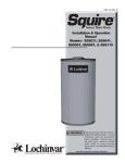
1
SHP-I&S-02
INSTALLATION AND SERVICE MANUAL
COMMERCIAL ELECTRIC WATER HEATERS
52, 82, 119 Gallon, 9 kW - 54kW Input Models
3. Water heater corrosion and component failure caused
by air-borne chemical vapors is not covered under the
manufacturer's warranty.
4. Corrosion damage caused by current leakage due to
improper grounding of electrical systems or electronic
components to the storage tank and related piping is not
covered by the manufacturer's warranty.
5. Under no circumstance will the manufacturer be liable
for consequential damages resulting from the
installation or use of this equipment.
6. Correct installation procedure and local codes must be
adhered to.
SPECIAL INSTRUCTIONS
TO OWNER
NOTE:
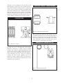
FIG. 1 Front View Vertical Round Models
Retain this manual for future reference.
Installation and service must be performed by Qualified
Service Personnel Only.
This manual supplies information for the installation,
operation and servicing of the appliance. It is strongly
recommended that this manual be reviewed completely
before proceeding with an installation.
WARRANTY
WARNING:
Factory warranty (shipped with unit) does not apply to
units improperly installed or improperly operated.
IMPROPER INSTALLATION, ADJUSTMENT,
ALTERATION, SERVICE OR MAINTENANCE can
cause injury or property damage. Refer to this
manual. For assistance or additional information,
consult a qualified installer, service agency or the
electric utility.
Experience has shown that improper installation or system
design, rather than faulty equipment, is the cause of most
operating problems.
CHECKING EQUIPMENT
1. Excessive water hardness causing a lime/scale build-up
in the heater and/or on the immersion heating elements
is not the fault of the equipment and is not covered
under the manufacturer's warranty. (See Water
Treatment and Water Chemistry)
Upon receiving equipment, check for signs of shipping
damage. Pay particular attention to parts accompanying
the water heater, which may show signs of being hit or
otherwise being mishandled. Verify total number of pieces
shown on packing slip with those actually received. In case
there is damage or a shortage, immediately notify carrier.
2. Do not energize electrical system before the heater is
completely filled with water. Damage caused to the
immersion heating elements by dry fire is not covered
under the manufacturer's warranty. Follow start up
procedure in the manual.
DO NOT USE THIS APPLIANCE IF ANY PART HAS
BEEN UNDER WATER. THE POSSIBLE DAMAGE TO A
FLOODED APPLIANCE CAN BE EXTENSIVE AND
PRESENT NUMEROUS SAFETY HAZARDS. ANY
APPLIANCE THAT HAS BEEN UNDER WATER MUST
BE REPLACED.
1
CONTENTS
WARNING:
Warranty . . . . . . . . . . . . . . . . . . . . . . . . . . . . . . . . . . . . . .1
Safety Warnings . . . . . . . . . . . . . . . . . . . . . . . . . . . . . . . . .1
Checking the Equipment . . . . . . . . . . . . . . . . . . . . . . . . .1
Codes . . . . . . . . . . . . . . . . . . . . . . . . . . . . . . . . . . . . . . . . .3
Installation Requirements
Location . . . . . . . . . . . . . . . . . . . . . . . . . . . . . . . . . . . . . . .3
Drain Pan Requirements . . . . . . . . . . . . . . . . . . . . . . . . .3
Clearances . . . . . . . . . . . . . . . . . . . . . . . . . . . . . . . . . . . . .4
Mounting . . . . . . . . . . . . . . . . . . . . . . . . . . . . . . . . . . . . . .4
Water Connections . . . . . . . . . . . . . . . . . . . . . . . . . . . . . .4
Tank Construction . . . . . . . . . . . . . . . . . . . . . . . . . . . . . .5
Relief Valve . . . . . . . . . . . . . . . . . . . . . . . . . . . . . . . . . . . . .5
Cathodic Protection . . . . . . . . . . . . . . . . . . . . . . . . . . . . .5
Electrical Service
Electrical Connection . . . . . . . . . . . . . . . . . . . . . . . . . . . .6
Wire Sizing . . . . . . . . . . . . . . . . . . . . . . . . . . . . . . . . . . . .6
Fusing . . . . . . . . . . . . . . . . . . . . . . . . . . . . . . . . . . . . . . . . .6
Electrical Connection . . . . . . . . . . . . . . . . . . . . . . . . . . . .6
Jacket Assembly . . . . . . . . . . . . . . . . . . . . . . . . . . . . . . . . .7
Standard and Optional Controls . . . . . . . . . . . . . . . . . . .7
Components and Controls
Terminal Block . . . . . . . . . . . . . . . . . . . . . . . . . . . . . . . . .7
Fuses and Fuse Blocks . . . . . . . . . . . . . . . . . . . . . . . . . . . .8
Surface Thermostats . . . . . . . . . . . . . . . . . . . . . . . . . . . . .8
Contactors . . . . . . . . . . . . . . . . . . . . . . . . . . . . . . . . . . . . .9
Transformer . . . . . . . . . . . . . . . . . . . . . . . . . . . . . . . . . . . .9
Immersion Thermostat . . . . . . . . . . . . . . . . . . . . . . . . . . .9
Temperature Regulation . . . . . . . . . . . . . . . . . . . . . . . . .10
Risk of Scald Warnings . . . . . . . . . . . . . . . . . . . . . . . . . .10
Temperature Limit Control . . . . . . . . . . . . . . . . . . . . . .11
Immersion Heating Elements . . . . . . . . . . . . . . . . . . . .12
Start-Up Procedure
Thermal Expansion . . . . . . . . . . . . . . . . . . . . . . . . . . . . .12
Filling the Water Heater . . . . . . . . . . . . . . . . . . . . . . . . .12
Start-Up Checks . . . . . . . . . . . . . . . . . . . . . . . . . . . . . . .13
Shutdown Procedure . . . . . . . . . . . . . . . . . . . . . . . . . . . .14
Maintenance
T&P Relief Valve . . . . . . . . . . . . . . . . . . . . . . . . . . . . . . .14
Water Chemistry . . . . . . . . . . . . . . . . . . . . . . . . . . . . . . .14
Flushing the Tank . . . . . . . . . . . . . . . . . . . . . . . . . . . . . .15
Sediment Removal . . . . . . . . . . . . . . . . . . . . . . . . . . . . .15
Scale Removal - Elements . . . . . . . . . . . . . . . . . . . . . . . .15
Trouble Shooting
Not Enough Hot Water . . . . . . . . . . . . . . . . . . . . . . . . . .16
Water Is Too Hot . . . . . . . . . . . . . . . . . . . . . . . . . . . . . . .16
Water Heater Sounds . . . . . . . . . . . . . . . . . . . . . . . . . . .16
Leakage . . . . . . . . . . . . . . . . . . . . . . . . . . . . . . . . . . . . . . .16
If the information in this manual is not followed
exactly, a fire or explosion may result causing
property damage, personal injury or loss of life. Do
not store or use gasoline or other flammable vapors
and liquids in the vicinity of this or any other
appliance.
OWNER WARNING:
The information contained in this manual is
intended for use by qualified professional installers,
service technicians or the electric utility. Consult
your local expert for proper installation or service
procedures.
IMPORTANT:
Consult and follow local Electrical Codes, Building
and Fire Regulations and other Safety Codes that
apply to this installation. Consult local codes
officials and electric utility company to authorize
and inspect all field installed electrical connections.
CAUTION
Be sure to turn off power when working on or near
the electrical system of the water heater. Never touch
electrical components with wet hands or when
standing in water. When replacing fuses, always use
the correct size for the circuit. Do not test electrical
system before the water heater is completely filled
with water. Follow the start-up procedure.
WARNING:
To minimize the possibility of serious personal
injury, fire or damage to your appliance, never violate
the following safety rules.
2
1.
Always keep the area around your appliance free of
combustible materials, gasoline, and other flammable
liquids and vapors.
2.
Never cover your appliance, lean anything against it,
store trash or debris near it, stand on it or in any way
block the access to your appliance.
CODES
6. The floor on which the appliance is installed must be
capable of supporting the total weight of the water
heater when completely filled with water. Combustible
floor locations may be used. Maintain required
clearances from combustible surfaces.
The equipment shall be installed in accordance with those
installation regulations in force in the local area where the
installation is to be made. These shall be carefully followed
in all cases. Authorities having jurisdiction shall be
consulted before installations are made. In the absence of
such requirements, the installation shall conform to the
latest edition of the National Electrical Code, NFPA 70.
When the appliance is installed in Canada, it must conform
to the CAE C22.1, Canadian Electrical Code, Part 1 and/or
local Electrical Codes.
7. The appliance must not be installed on carpet.
8. The appliance must be installed indoors where it is
protected from exposure to wind, rain and weather.
9. Locate the appliance as close as possible to the point of
major hot water usage, the water piping and branch
electrical circuit wiring.
APPROVALS
This complete appliance is design certified and Listed by
Underwriters Laboratories as a commercial storage electric
water heater. This water heater bears the UL certification
for the United States as tested under the Standard for
Electric Booster and Commercial Storage Tank Water
Heaters, UL1453 and C-UL in Canada as tested under the
Standard for Construction and Test of Electric Storage Tank
Water Heaters, CAN/CSA-C22.2 No. 110-M90.
10. Insulate water piping to control heat loss and possible
condensation.
11. The appliance must be located in an area that is not
subject to freezing. The ambient temperature of the
space where the appliance is installed must not go below
32°F (0°C) or above 104°F (40°C).
CAUTION
INSTALLATION PROCEDURE
This water heater, as well as all water heaters will
eventually leak. Installation of the water heater
should be accomplished in such a manner that if the
tank, piping or any connections should leak, the flow
of water will not cause damage to the structure. For
this reason, it is not advisable to install the water
heater in an attic or upper floor. When such
locations cannot be avoided, a suitable drain pan
must be installed under the water heater. Drain pans
may be fabricated or purchased from your plumbing
wholesaler. The drain pan must be piped to an
adequate drain. Under no circumstances is the
manufacturer to be held liable for any water damage
in connection with this water heater.
LOCATION OF UNIT
1. Locate the appliance so that if water connections should
leak, water damage will not occur. When such locations
cannot be avoided, it is recommended that a suitable
drain pan, adequately drained, be installed under the
unit. Under no circumstances is the manufacturer to be
held responsible for water damage in connection with
this unit, or any of its components.
2. Insure that the appliance is located near an acceptable
drain so that the vessel can be properly drained when
performing service or maintenance. The drain must
a
l
s
o
provide adequate drainage in the event of leakage from
the tank or related piping. The drain must prevent water
damage to the adjacent area and lower floors of the
structure.
3. The appliance must be installed so that the electrical
components are protected from water (dripping,
spraying, etc.) during appliance operation and service
(replacing of fuses, elements, etc.)
4. Appliances located in a garage or parking structure shall
be installed so that the jacket and all piping shall be
located or protected so that it is not subject to physical
damage by a moving vehicle.
5. The appliance must be installed on a level floor. Shim
the base as necessary if leveling is required.
3
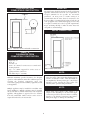
MOUNTING
CLEARANCES FROM
COMBUSTIBLE CONSTRUCTION
The water heater should be mounted to the floor following
applicable architectural and local code requirements or
accepted standards for the specific site and model
purchased. In areas prone to seismic activity, it is
recommended that the water heater be mounted to the
floor according to recommended procedures for the site. In
some geographic areas, additional strapping or braces may
be required, consult local codes for specific requirements.
Proper mounting will help to make the water heater less
susceptible to seismic damage.
WATER CONNECTIONS
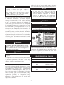
FIG. 2
Clearances from Combustible Construction
TABLE - A
CLEARANCES FROM
COMBUSTIBLE CONSTRUCTION:
Right Side - 0"
Rear - 0"
Left Side - 0"
Front - 18" (45cm) for service access to controls and
heating elements
Top - 12" (30cm) suggested for service access to
piping and water connection
Hot Water Pipes 1" (25.4mm)
FIG. 3 Water Connections
NOTE:
Before making any connections to the cold water
inlet or hot water outlet, insure that all piping is clean
and free of material or scale. This can usually be
accomplished by "blowing out the pipe." Any foreign
material or scale entering the water heater can
adversely affect operation and performance.
Maintain minimum specified clearances for adequate
operation. All installations must allow sufficient space for
servicing the electrical components, water pipe
connections, piping and other auxiliary equipment, as well
as the appliance.
NOTE:
Multiple appliances may be installed in a modular water
heater installation. Multiple appliances may be installed
side by side with no clearance between the sides of adjacent
appliance. This appliance is approved for zero clearance
from side combustible surfaces and no service access is
required from the sides on most models.
When using copper tubing, solder tubing to an
adapter before attaching to the threaded nipple
connection provided on the water heater. Soldering
directly to the threaded connection may harm a
lining in the nipple or damage the tank lining.
4
CAUTION
INLET AND OUTLET CONNECTIONS
Avoid contact with hot discharge water. Insure that
no one is in front of or around the relief valve
discharge line. Make sure that the extremely hot
water manually discharged from the relief valve will
not cause bodily injury or property damage.
For ease of service, install unions on the cold water inlet
and hot water outlet of the water heater. The cold water
inlet connection is located on the lower left front side of the
water heater. A manual shutoff valve should be installed
upstream on the cold water source as an isolation device.
The hot water outlet connection is located on the top center
of the water heater. A manual shutoff valve should be
installed downstream on the hot water outlet source as an
isolation device in case the water heater must be
disconnected from the system.
THERMAL EXPANSION
OF WATER
A relief valve that discharges periodically may be due to
thermal expansion in a closed system. Many water systems
are equipped with pressure reducing valves, check valves or
back flow preventers which may cause the water system to
be closed. As water is heated it will expand in volume due
to thermal expansion. The system must make allowance for
this expansion. If an expansion tank is not provided in the
system, water pressure may increase to the point where the
water heater's temperature and pressure relief valve opens
to relieve the excess pressure. The temperature and
pressure relief valve is not intended for the constant relief of
thermal expansion. This is an unacceptable condition and
must be corrected. Do not plug or cap the relief valve
discharge! A properly sized expansion tank is typically
installed in the potable water system to relieve the pressure
built up by thermal expansion of heated water. Consult
your local plumbing contractor and plumbing wholesaler
for assistance in properly selecting an expansion tank for
your system.
STORAGE TANK
This appliance uses a glass lined steel storage tank to store
the heated water for use. The storage tank is constructed
in accordance with the requirements of the Underwriters
Laboratory Listing for a commercial electric water heater.
The tank is furnished with threaded connections for cold
water inlet, hot water outlet, a relief valve and a drain
connection. The storage tank has a hand hole for ease of
inspection, cleanout and service. The interior of the
storage tank is glass lined and fired to 1600˚F (871˚C) to
insure a molecular fusing of glass and steel to protect the
steel base metal against corrosion. A magnesium anode is
standard to help prevent dissipation of the tank material by
electrolytic action.
RELIEF VALVE
This water heater is supplied with a temperature and
pressure relief valve(s) sized in accordance with ASME
Boiler and Pressure Vessel Code, Section IV. Some water
heaters may be supplied with an optional pressure only
relief valve. The relief valve(s) is installed in the vertical
position and mounted in the tapping provided in the
storage tank. No valve is to be placed between the relief
valve, and the water heater. To prevent water damage, the
discharge from the relief valve must be piped to a suitable
floor drain for disposal when relief occurs. No reducing
couplings or other restrictions shall be installed in the
discharge line. The discharge line shall allow complete
drainage of the valve and line. Relief valves should be
manually operated at least once a year. A relief valve that
fails to completely reseat and continues to discharge water
must be immediately replaced with a new, properly sized,
temperature and pressure relief valve.
As the water heater operates, there may be noises generated
by the expansion and contraction of the metal parts of the
water heater and related piping. These noises may occur
during periods of heat up or cool down. They do not
represent harmful or dangerous conditions.
CATHODIC PROTECTION
Hydrogen gas can be produced in a hot water system that
has not been used for a long period of time (generally two
weeks or more). Hydrogen gas is extremely flammable. To
prevent the possibility of injury under these conditions, we
recommend the hot water faucet be open for several
minutes at a sink close to the water heater before you use
any electrical appliance which is connected to the hot water
system. If hydrogen is present, there will be an unusual
sound such as air escaping through the pipe as the hot
water begins to flow. There should be no smoking or open
flames near the faucet at the time it is open.
5
ELECTRICAL CONNECTIONS
1. Use copper conductors only. All wiring between the
appliance and field installed devices shall be made with
copper wire suitable for at least 167°F (75°C)
temperature rating. If the wiring from an old water
heater installation was aluminum, replace the old wire
with copper wire.
All installation procedures involving electric power
connection should only be performed by a trained, certified
electricians.
2. The factory internal wiring is attached to a terminal
block inside the unit. The branch circuit is connected to
the terminal block through an opening provided on the
top of the water heater electrical access panel.
3. Line voltage wire exterior to the appliance must be
enclosed in approved conduit or approved metal clad
cable.
4. To avoid serious damage, DO NOT energize the
appliance until the system is full of water. Ensure that
all air is removed from the storage tank and piping before
beginning initial operation. Operation of a water heater
without a completely filled tank may result in serious
damage to the appliance and heating element burn out.
5. The water heater should be connected with a separate
grounded branch circuit with over current protection
and disconnect switch. The water heater should be
grounded in accordance with national and local codes. A
ground terminal is provided for ground connection only.
FIG. 4 Electric Power Connections - Electrical Control
Panel
WARNING:
6. Provide the appliance with proper overload protection in
the branch circuit. It is suggested that the electrician size
the branch circuit at 125 percent of the heater ampere
rating and further increase wire size as necessary to
compensate for voltage drop in long runs. Branch circuit
voltage drop should not exceed 3% at the heater.
WATER HEATER IS EQUIPPED FOR OPERATION
ON ONE VOLTAGE ONLY. Check the rating plate
on the front of the control panel access for the
correct voltage and phase. DO NOT use this water
heater with any other voltage other than the voltage
specified on the rating plate. Failure to use the
correct voltage can cause problems that can result
in death, serious bodily injury or property damage.
7. Voltage applied to the heater should not vary more than
+5% to -10% of the model and rating plate marking for
satisfactory operation.
CAUTION
8. A wiring diagram is provided with the water heater for
the electricians use.
DO NOT CONNECT THE WATER HEATER TO AN
IMPROPER SOURCE OF ELECTRICITY!
CAUTION
The appliance, when installed, must be electrically
grounded in accordance with the requirements of the
authority having jurisdiction or in the absence of such
requirements, with the latest edition of the National
Electrical Code, NFPA No. 70. When the appliance is
installed in Canada, it must conform to the CAE C22.1,
Canadian Electrical Code, Part 1 and/or local Electrical
Codes.
Never turn on the electric power or attempt to use
this electric water heater unless it is completely full of
water. Water must flow from the hot water faucet
before turning electrical power "ON." Operation of a
water heater without a completely filled tank may
result in serious damage to the appliance and heating
element burn out.
6
JACKET ASSEMBLY
• Underwriter's Laboratories, Inc. listing for all models as a
commercial electric water heater.
Outer Jacket - The outer jacket assembly is constructed
from heavy gauge steel. The exterior surface is specially
prepared and phosphate coated to allow application of a
multiple coat enamel paint process. This coating process
insures a long life from the jacket assembly.
The following items are available as extra cost options.
• Immersion thermostats with magnetic contactors
COMPONENTS AND CONTROLS
STANDARD EQUIPMENT
Your commercial electric water heater is equipped with the
following as standard equipment.
• Low watt density immersion heating elements with a
copper sheath and a tin plate.
• Internal fusing of all element power circuits is provided
when current draw is in excess of 48 amps
• Fused power circuits provided in increments of a
maximum 48 amps for additional safety.
• Fuse cartridges are rated at 1,000,000 amps interrupting
capacity.
• A fully painted heavy gauge steel outer jacket and
electrical control panel are provided.
• Electrical control panel is provided with a hinged door.
• A glass lined steel tank constructed to standard
specifications and provided with a magnesium anode.
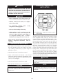
FIG. 5
• ASME rated temperature and pressure relief valve
provided by factory to insure safe heater operation.
Electrical Control
Location Drawing
Panel
TERMINAL BLOCK
• Terminal block connections are installed by the factory for
safe easy wiring connection.
• Manual reset high water temperature limit control.
• Surface mount thermostats (one per each immersion
heating element).
• 180°F temperature operation is possible to provide water
for sanitizing applications.
• Insulated to meet latest edition of ASHRAE 90.1 energy
efficiency standards.
• 3 year limited warranty provides protection against failure
of tanks due to defects in material and workmanship in
commercial application.
FIG. 6 Main Power Terminal Block
7
Component
SURFACE THERMOSTATS
WITH HIGH LIMIT
A main power terminal block is provided for field
connection of the branch power supply to the electric water
heater. All internal power circuits to the immersion heating
elements are connected to the load side of the main
terminal block. The line side of the terminal block has
individual lug type connections properly sized for the
recommended copper field wire size.
FUSES AND FUSE BLOCKS
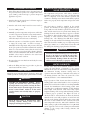
FIG. 8 Surface Thermostat/High Limit
WARNING:
HAZARD OF ELECTRICAL SHOCK - Before
opening the electrical access panel to adjust the
thermostat or servicing the water heater, make sure
the electrical supply to the water heater is turned
"OFF". Failure to do this could result in death,
serious bodily injury or property damage.
FIG. 7 Fuse Block with Power Circuit Fuses
The internal power circuits of a water heater with a current
draw in excess of 48 amps are fused for safety. Each power
circuit to an immersion element is fused at a maximum of
48 amps. Power circuits may be fused at lower current levels
as needed to balance current on three phase units. The
power circuit fuses are held by a spring loaded fuse block
rated for the voltage specified to operate the water heater.
The standard control system uses an individual surface
mounted snap action thermostat with high limit for each
heating element. The thermostat/high limit is mounted
firmly against the tank, directly above each heating element.
The surface thermostat has an adjustable temperature
setting that can be varied from 110°F (43.3˚C) up to 180°F
(82.2˚C) at the highest setting. Turn off all electrical power
to the water heater before attempting to adjust the
thermostats. The temperature setpoint adjustment is made
on each thermostat by using a screwdriver. All surface
thermostats may be set at the same temperature or they may
be set a 2° to 4°F (1˚ to 2˚C) apart to step the elements on in
stages. There is a blanket of fiberglass insulation installed
over the heating elements and surface thermostats. This
insulation must be removed before the thermostats can be
adjusted. Each thermostat has a plastic cover installed to
prevent accidental contact with power wires when adjusting
the set point. This cover has an opening to allow
temperature adjustment and resetting of the high limit.
The cover does not have to be removed. The high water
temperature limit control which is part of each thermostat
assembly contains a manual reset on high water
temperature.
When the immersion thermostat and contactor option is
provided, the control circuit is also fused on the primary
side of the control circuit transformer.
8
CONTROL CIRCUIT TRANSFORMER
The limit is reset by pushing the red reset button on the
limit. Operation of the limit control usually indicates a
major problem with the heating elements or temperature
control. Do not continue to push the reset multiple times.
The problem causing the reset to function must be found
and corrected to insure proper operation. The blanket of
fiberglass insulation must be replaced over the surface
thermostats and immersion heating elements before the
power is turned on and the heater is returned to service.
CONTACTORS
FIG. 10 Control Circuit Transformer
When the immersion thermostat and contactor option is
provided, a transformer is used to reduce the line voltage to
120 VAC for internal control operation. The transformer is
fused on the primary side. The VA rating of the control
circuit transformer is based on the load of the various
components in the water heater control circuit.
IMMERSION THERMOSTAT(S)
FIG. 9 Magnetic Contactor
When the immersion thermostat and contactor option is
provided, the power to the immersion electric heating
elements is switched by a definite purpose magnetic
contactor. The contactor is supplied with 120 VAC from the
control circuit when the immersion thermostat senses a
drop in stored water temperature below the desired set
point. A magnetic coil in the contactor is energized to
complete the electric circuit supplying power to the
immersion heating elements. When the thermostat is
satisfied, the contactor coil is de-energized and power to the
heating elements is turned off.
FIG. 11 Immersion Thermostat
9
WARNING:
Allow a few days of operation at the setting to determine
the correct temperature setting consistent with your needs.
HAZARD OF ELECTRICAL SHOCK - Before
opening the electrical access panel to adjust the
thermostat or servicing the water heater, make sure
the electrical supply to the water heater is turned
"OFF". Failure to do this could result in death,
serious bodily injury or property damage.
NOTE:
(1) This water heater, when set at the lower
temperature setting, is not capable of producing hot
water of sufficient temperature for sanitizing
purposes. (2) Higher stored water temperature
increases the ability of the heater to supply desired
quantities of hot water, however remember:
As a control option, the water heater may be provided with
an immersion thermostat(s) to activate magnetic
contactors allowing current to flow to the immersion
heating elements. The immersion thermostat option may
use up to one immersion thermostat for each 36kW of
electric heating power in a water heater. The sensing bulb
for each immersion thermostat is immersed in the stored
water in the tank to provide quick, accurate response to
changes in water temperature. The thermostat sensing bulb
is located in the tank just above the elements it is
controlling. The immersion thermostat set point is
adjustable by rotating a knob on the control. Turning the
knob counter clockwise decreases the temperature set point
and turning the knob clockwise increases the set point. The
temperature setting shown at the top of the knob is the
selected set point. The immersion thermostat has a fixed
6°F (3.3˚C) differential.
CAUTION
Hotter water increases the risk of scald injury.
CAUTION
Setting the temperature selector dial higher provides
hotter water, which increases the risk of scald injury.
TEMPERATURE REGULATION
WARNING:
WARNING! HAZARD OF ELECTRICAL SHOCK Before opening the electrical access panel to adjust
the thermostat, make sure the electrical supply to the
water heater is turned "OFF".
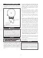
FIG. 12 Hot Water Danger Label
The following chart details the relationship of water
temperature and time with regard to scald injury and may
be used as a guide in determining the safest water
temperature for your applications.
DANGER
APPROXIMATE TIME / TEMPERATURE
RELATIONSHIPS IN SCALDS
Full power is present whenever the cabinet door is
opened.
Set temperature control to the lowest setting which satisfies
the hot water requirements of the system. Lower water
temperatures help minimize scale formation on the heating
elements. See thermostat information below.
WATER TEMPERATURE SETTINGS
This water heater has an adjustable thermostat(s) to control
water temperature. The thermostat is factory pre-set at
approximately 125°F (51.7°C) or less. Households with
small children or invalids may require a 120°F (48.9°C) or
lower temperature setting to reduce risk of scald injury.
Some states may require a lower temperature setting.
Check with your local codes or electric utility for local
requirements governing the temperature setting.
Remember, no water heating system will provide exact
temperatures at all times.
10
120°F
More than 5 minutes
125°F
1 1/2 to 2 minutes
130°F
About 30 seconds
135°F
About 10 seconds
140°F
Less than 5 seconds
145°F
Less than 3 seconds
150°F
About 1 1/2 seconds
155°F
About 1 second
HIGH WATER TEMPERATURE
LIMIT CONTROL
WARNING:
SHOULD OVERHEATING OCCUR OR THE
TEMPERATURE CONTROLS FAIL TO SHUT OFF,
TURN OFF OR DISCONNECT THE ELECTRICAL
SUPPLY AT THE MAIN POWER DISCONNECT,
EXTERNAL TO THE APPLIANCE.
DANGER
• Water temperature over 125°F (51.7°C) can
cause severe burns instantly or death from scald.
• Children, disabled and elderly are at highest
risk of being scalded.
• See instruction manual before
temperature at heating appliance.
setting
• Feel water before bathing or showering.
• If this appliance is used to produce water that
could scald if too hot, such as domestic hot
water use, adjust the outlet control (limit) or
use temperature limiting valves to obtain a
maximum water temperature of 125˚F (51.7˚C).
FIG. 13 High Water Temperature Limit Control Fixed Setting
The unit is equipped with a fixed setting, manual-reset high
water temperature limit control(s). The water heater
temperature limit control has a fixed limit setting of 195°F
(90.6°C). If water temperature exceeds the limit set point,
the limit will break the control circuit and shut down the
unit. The limit control can only be reset after the water
temperature has cooled below the set point of the limit. The
high water temperature limit control for the standard
surface thermostat controls is the contained in the upper
portion of the surface thermostat and mounted above each
heating element. The high water temperature limit control
for the immersion thermostat and contactor option is
mounted on the surface of the tank, above the heating
element installed at the highest point in the tank. The limit
control is covered with an insulation blanket which must be
removed to push the red reset button.
Always close the electrical control panel door after
making a temperature adjustment. Turn on
electricity.
TEMPERATURE ADJUSTMENT
1. Turn "OFF" the electrical power to the water heater. If
the power disconnect point is out of sight, lock it in the
open ("OFF") position and tag to prevent unexpected
application of power.
2. Open the water heater's electrical access panel.
3. Adjust each immersion thermostat to the desired
temperature setting by turning the adjusting knob. Each
thermostat will be factory pre-set to approximately 125°F
(51.7°C) or less as shipped.
CAUTION
Disconnect the main power to the heater before
opening the element access panel to reset the high
limit control.
4. Close the water heater's electrical access panel.
5. Turn "ON" the electrical power to the water heater.
NOTE:
CAUTION
The high limit control will not reset until the water
temperature has dropped below the set point of the
high limit.
The maximum temperature setpoint that should be
set for the Surface or Immersion Thermostats is
190°F (88°C).
11
START-UP PROCEDURE
IMMERSION HEATING ELEMENTS
Never operate the heating elements without being certain
the water heater is filled with water and a temperature
and pressure relief valve is installed in the relief valve
opening on top of the heater.
DANGER
Full power is present whenever the cabinet door is
opened.
THERMAL EXPANSION
Many water systems are equipped with pressure reducing
valves, check valves or back flow preventers which may
cause the water system to be closed. As water is heated, it
will expand in volume due to thermal expansion. The
system must make allowance for this expansion. If an
expansion tank is not provided in the system, water
pressure may increase to the point where the water heater's
temperature and pressure relief valve opens to relieve the
excess pressure. The temperature and pressure relief valve is
not intended for the constant relief of thermal expansion.
This is an unacceptable condition and must be corrected. A
properly sized expansion tank is typically installed in the
potable water system to relieve the pressure built up by
thermal expansion of heated water. Consult your local
plumbing contractor and plumbing wholesaler for
assistance in properly selecting an expansion tank for your
system.
FIG. 14 Immersion Heating Element
WARNING:
HAZARD OF ELECTRICAL SHOCK - Before
opening the access panel to remove or service the
immersion heating elements, make sure the electrical
supply to the water heater is turned "OFF". Failure to
do this could result in death, serious bodily injury or
property damage.
As the water heater operates, there may be noises generated
by the expansion and contraction of the metal parts of the
water heater and related piping. These noises may occur
during periods of heat up or cool down. They do not
represent harmful or dangerous conditions.
The heating input to this commercial electric water heater
is provided by low watt density immersion heating
elements. The heating elements are constructed from a
copper sheath with a tin plate on the exterior surface.
Individual element blades are mounted on a hex-head
screw-in mounting flange. The element flange mounts into
a 1" NPT threaded connection welded to the storage tank.
The hex-head screw-in mounting flange seals to the tank
with an "O" ring gasket at the base of the threaded portion
of the flange. The tank flange has a matching recess for the
"O" ring gasket to insure a proper water tight seal. The "O"
ring element gasket must be replaced with a new gasket
when an element is removed for inspection, cleaning or
replacement.
FILLING THE WATER HEATER
1. Insure that the electrical power to the water heater is in
the "OFF" position. If the power disconnect point is out
of sight, lock it in the open ("OFF") position and tag to
prevent unexpected application of power.
2. Close the water heater drain valve(s).
3. Open a nearby hot water faucet to allow the air in the
system to escape as the tank fills.
DANGER
4. Fully open the cold water inlet valve to the water heater
to begin filling the heater and piping.
HAZARD OF ELECTRICAL SHOCK - Full power is
present whenever the cabinet door is opened and
main power is turned "ON".
12
NOTE:
12. As the water heater starts heating, check the contactors
for "buzzing" or "chattering" during operation. If noise
is detected, turn off main power, open the control panel
and clean the contact points of the magnetic
contactor(s). Remove any dust, dirt or foreign matter
that may have found its way into the contactor or other
electrical components in the control panel during
shipping, installation or service.
The cold water supply must be left in the open
position when the water heater is in use.
5. Check the nearby hot water faucet to verify that air is
exiting the tank as it fills with water. Allow water to run
until a constant flow is obtained at the faucet. This will
insure that all air is purged from the system.
13. Close the electrical control panel and turn on main
power.
CAUTION
The power supply must remain off until the water
heater and all related piping are completely filled
with water to insure that there will not be a possible
problem with heating element burn out.
14. The water heater is now ready for normal operation.
INITIAL START UP CHECKS
The following checks should be made by the installer when
the water heater is placed into operation for the first time.
6. While the tank is filling, open the electrical control
panel and set the immersion thermostat(s) to the
desired water temperature. Open the element access
panel to set the surface mount thermostats above each
immersion heating element. If equipped with multiple
thermostats, all individual thermostats may be adjusted
to the same temperature set point or they may be set a
2° to 4°F (1˚ to 2˚C) apart to step the elements on in
stages.
WARNING:
HAZARD OF ELECTRICAL SHOCK - Before
opening the access panel to perform service on any
electrical component, make sure the electrical supply
to the water heater is turned "OFF". Failure to do this
could result in death, serious bodily injury or
property damage.
1. Allow the water heater to heat for approximately thirty
minutes after following the filling and start up
procedures.
7. When a constant flow is obtained at the faucet, it may be
turned off. The temperature and pressure relief valve
should be manually opened to insure that there is no
captive air in the storage tank. A constant stream of
water must flow from the manually opened relief valve.
Release the handle on the relief valve and allow it to
close after water flow is observed.
2
8. Carefully check the tank, pipe and fittings for any sign
of a water leak. Immediately repair as needed. Open the
access door to the immersion heating elements and
check for leaks at the element mounting flanges. If any
leak is detected, tighten the screw-in element.
Turn off the main electrical power to the water
heater. If the power disconnect point is out of sight, lock
it in the open ("OFF") position and tag to prevent
unexpected application of power.
3. Open the electrical control panel door and feel each wire
connection and fuse clip for excessive temperature. If
any connection is found to be excessively hot, check the
tightness of the connection. Check all factory internal
wiring connections and the field made main power
connections for tightness.
START UP
9. Ensure that the electrical access panel (field wiring
compartment) is closed and the heating element access
panel is in place before proceeding.
4. Close and lock the electrical control panel door.
10. After assuring that the tank is completely filled with
water and no leaks are detected, you are now ready to
start operation of the water heater.
6. Temperature control and contactor operation should be
checked by allowing the water heater to come up to
temperature and shut off automatically.
11. Turn on the electric power at the main disconnect
point.
On immersion thermostat models, the
contactors should be energized as the elements start to
heat the water in the tank.
7. The water heater is now ready continuous normal
operation.
5. Turn on the main electrical power to the water heater.
13
SHUTDOWN PROCEDURE
TEMPERATURE AND PRESSURE RELIEF
VALVE OPERATION
1. Turn off the main electrical power to the water heater. If
the power disconnect point is out of sight, lock it in the
open ("OFF") position and tag to prevent unexpected
application of power.
The temperature and pressure relief valve(s) should be
manually operated at least once a year. A relief valve that
fails to completely reseat after manual operation and
continues to discharge water must be immediately replaced
with a new, properly sized, temperature and pressure relief
valve.
2. Turn the valve in the water heater's cold water supply to
the closed or "OFF" position.
3. Turn the valve in the water heater's hot water outlet to
t
h
e
closed or "OFF" position.
The relief valve(s) should be installed in the vertical
position and mounted in the tapping provided in the
storage tank. No valve should be placed between the relief
valve, and the water heater. To prevent water damage, the
discharge from the relief valve must be piped to a suitable
floor drain for disposal when relief occurs. No reducing
couplings or other restrictions shall be installed in the
discharge line. The discharge line shall allow complete
drainage of the valve and line. The discharge line from the
relief valve should be metallic pipe or a high temperature
plastic pipe (CPVC, etc.) to insure that hot water flow will
not damage the discharge piping from the relief valve.
4. Manually open the temperature and pressure relief valve
to remove any pressure from the storage tank. Caution!
Any water discharged from the manually opened
relief valve may be hot and cause a scald injury.
5. Allow the system to cool and then open the drain valve
to empty the storage tank. It will be necessary to
manually hold the temperature and pressure relief valve
in the open position to break the vacuum in the tank and
allow it to vent and drain. Insure that the water heater
drain is routed to a properly sized floor drain to allow the
water to be removed from the tank. If a floor drain is not
available, a hose may be attached to the water heater
drain to take the water outdoors.
CAUTION
Avoid contact with hot discharge water. Insure that
no one is in front of or around the relief valve
discharge line. Make sure that the extremely hot
water manually discharged from the relief valve
will not cause bodily injury or property damage.
6. The water heater is now shut down and ready for service
or maintenance.
WATER CHEMISTRY
7. Follow the filling and start up procedure to place the
water heater back into service.
In hard water areas, water treatment should be used to
reduce the introduction of minerals to the system.
Minerals in the water can collect in the storage tank and on
the immersion heating elements causing noise on
operation. Excessive build up of minerals on the surface of
the heating elements can reduce the service life of the
elements and lead to a non-warrantable failure.
MAINTENANCE
Listed below are items that must be checked to insure safe
reliable operations. Verify proper operation after servicing.
WARNING:
Proper operation of this electric water heater is based on
heating potable water with a hardness of 5 to 25 grains per
gallon and a total dissolved solids not exceeding 350 PPM.
Consult the manufacturer when heating potable water
exceeding these specifications. Heating of high hardness
and/or high total dissolved solids water may require
frequent cleaning of the storage tank and heating elements
to achieve proper operation. The higher the level of
dissolved solids or water hardness, the faster the dissolved
minerals in the water will precipitate out and form scale
deposits on the heating elements and in the storage tank.
The level of scale formation is also accelerated as stored
water temperature increases. Water with a hardness of less
than 5 grains per gallon will usually have a low pH which
can be aggressive and corrosive causing non-warrantable
damage to the storage tank, heating elements and
associated piping.
HAZARD OF ELECTRICAL SHOCK - Before
opening the electrical access door, removing the
heating element access panel or servicing the water
heater, make sure the electrical supply to the water
heater is turned "OFF". Failure to do this could
result in death, serious bodily injury or property
damage.
CAUTION
Label all wires prior to disconnection when
servicing controls. Wiring errors can cause
improper and dangerous operation.
14
Corrosion due to water chemistry generally shows up first
in the hot water system because heated water increases the
rate of corrosive chemical reactions.
Water heater maintenance includes periodic tank flushing
and cleaning and removal of lime scale from the heating
elements. Where used, the water heating system circulating
pump should be oiled.
FLUSHING THE STORAGE TANK
1. Turn off main power at the electrical disconnect switch.
2. Open the drain valve. Allow water to flow until it runs
clean.
3. Close the drain valve when finished flushing.
4. Open a hot water faucet closest to the water heater and
the water to run to insure that no air was drawn into
the tank during the flushing process. Close the faucet
when the water runs clear with no discharge of air.
5. Turn on main power the electrical disconnect switch
(after filling).
SEDIMENT REMOVAL
Water born impurities consist of dissolved minerals which
precipitate out of the heated water and fine particles of soil
and sand which settle out and form a layer of sediment on
the bottom of the tank. In time, if not removed, the level of
sediment might reach the heating elements.
For convenience, sediment removal and element lime scale
removal should be performed at the same time. Proceed
with the following instructions:
cleaned from the bottom of the tank.
NOTE:
All gaskets on disassembled clean-out openings
must be replaced with new gaskets on
re-assembly. Gaskets are available from your
distributor.
Water scale accumulations on the immersion heating
element reduce the ability of the elements to heat water and
may cause noise to occur during operation. It is
recommended that a heating element be removed at least
once a year for examination. If it is scaled, all of the
elements should be removed and cleaned. The element
gasket must be replaced when the element is removed for
cleaning.
Small accumulations of lime scale may be removed with a
stiff bristle brush. Severe accumulations of lime scale
should be removed by dissolving the accumulation in a
commercial delimer. Do not use muratic or hydrochloric
acid base deliming solutions to remove lime scale from the
elements. Do not pour delimer into tank. Deliming
solutions may damage the glass lined interior of the tank.
DANGER
Keep all delimers away from anode rods to prevent
the formation of flammable and explosive gas.
1. Drain
the
heater
following
PROCEDURE" instructions.
"SHUTDOWN
Sediment and Lime Scale Removal
Sediment and lime scale accumulation on the heating
elements is a normal condition common to all immersion
type elements. Factors which affect the amount of this
formation are:
1. Amount of hot water used. As the volume of water
increases, more scale results.
2. Water temperature. As the temperature of the water is
increased, more scale is deposited on the elements.
3. Characteristics of water supply. Regardless of water
treatment, the elements should be examined regularly.
Scale accumulation in the bottom of the storage tank may
be removed by turning off main power and draining the
tank. Once all water is removed, the hand hole access can be
removed. This will allow large accumulations of scale to be
15
2. Disconnect the wires attached to the element terminals.
Try not to disturb the wiring unnecessarily and
reconnection will be easier.
3. Loosen the screw-in element flange with a socket and
breaker bar. Do not use an impact gun (air or electric) to
remove the element flanges from the tank. Mark the
location of each element in the tank openings so they
may be returned to their original position.
4. Remove the elements from the opening with a twisting,
pulling action if the elements are scaled beyond the size
of the tank flange openings. Brush loose scale from
elements.
5. Place scaled ends of heating elements into a deliming
solution and allow scale to dissolve. Do not permit the
delimer or water to contact heating element electrical
terminals.
6. Flush clean ends of elements with water when deliming
or cleaning is completed.
7. Clean remaining gasket recess on each screw-in element
flange. Do not reuse element gaskets.
8. Install a new gasket on each element. Install element into
the tank opening where it was originally installed.
Tighten the flange with the socket and breaker bar used
to remove the element.
9. Attach wires to element terminals from which they were
removed.
10. Follow "FILLING THE WATER HEATER" instructions
to restore hot water service. Check for water leaks
around elements and proper operation when heater is
filled.
TROUBLE SHOOTING
Checklist
Water is too hot
1. Refer to "Temperature Regulation" and reset the
thermostat setpoint to a lower temperature that will meet
requirements for hot water
Water heater makes sounds
1. Sediment or lime scale accumulation on the elements
causes sizzling and hissing noises, when the heater is
operating. If this occurs, the tank bottom and elements
should be cleaned. Refer to "MAINTENANCE" for
details.
2. Some of the electrical components of the water make
sounds which are normal. Contactors will "click" or snap
as the heater starts and stops. Transformers and
contactors often hum.
Water leakage is suspected
Before calling for service, check the following points to see
if the cause of trouble can be identified and corrected.
Reviewing this checklist may eliminate the need of a service
call and quickly restore hot water service.
Not enough or no hot water
1. Check to see if the drain valve is tightly closed.
2. The apparent leakage may be condensation which forms
on cool surfaces of the heater and piping.
3. If the outlet of the relief valve if leaking, it may represent:
1. Ensure that the electrical disconnect switch serving the
water heater is in the "ON" position. In some areas, water
heater electrical service may be limited by the power
company. If the heater operates on a controlled circuit,
heater recovery may be affected.
2. Check the fuses. The electrical disconnect switch usually
contains fuses. The water heater has fuses located behind
the cabinet front door. When replacing internal fuses in
the water heater control panel, insure that the same type
and size of fuse is used.
3. If the water was excessively hot and is now cold, the
manual reset high limit may have operated. To reset, turn
off electricity and push the reset button. The high limit is
located above the thermostat on surface thermostat
models, above the upper most heating element in the
storage tank on immersion thermostat models. Repeat
operation of the high temperature cut-off should be
investigated by your mechanical contractor or by a
qualified technician. A contactor or thermostat may be
malfunctioning.
4. The capacity of the heater may have been exceeded by a
large demand for hot water. Large demands require a
recovery period to restore water temperature.
a. Excessive water pressure.
b. Excessive water temperature.
c. Faulty relief valve.
Excessive water pressure is not the most common cause of
relief valve leakage. It is often caused by a "closed system."
A check valve, a back flow preventer or pressure reducing
valve, in the inlet system will not permit the expanded hot
water volume to equalize pressure with the main. A relief
valve must release this water or the water heater and
plumbing system will be damaged.
When such a condition is encountered, local codes or
inspection agency should be consulted to determine which
of the following procedures is acceptable in your area.
Installation of an expansion tank.
Removal of the check valve.
4. Examine the flange area of the elements for gasket
leakage. Tighten the screw-in flange or, if necessary,
follow the "Water and Lime Scale Removal" procedure to
remove the element and replace the "O" ring gaskets that
seal each element.
IF YOU CANNOT IDENTIFY
OR CORRECT THE SOURCE
OF MALFUNCTION:
5. Cold incoming water temperature will lengthen the time
required to heat water to the desired temperature. If the
heater was installed in the summer when incoming water
temperature was warm, colder ground water in the winter
months can create the effect of less hot water.
1. Place the water heater electrical disconnect switch on the
"OFF" position.
6. Look for wasted hot water and leaking or open hot water
faucets.
2. Contact your mechanical contractor or service
technician.
7. Sediment or lime scale may be affecting water heater
operation. Refer to "Maintenance" for details.
16
Revision Notes: Revision 2 (ECO #C02870) reflects the
addition of the scald chart on page 10.
CP-5M-1/09-Printed in U.S.A.