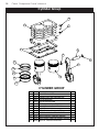
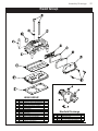
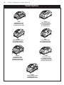
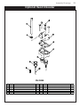
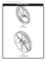
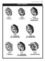
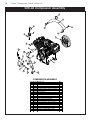
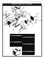
1
Owner’s Manual
Safety, Installation, Maintenance, and Operation
ModelV480Compressor
ModelsuH-60Compressor
ModelsHD-60Compressor
americaneagle,Inc.
740n.statestreet
POBox169
Garner,Ia50438
800-392-3015
Fax:641-923-9099
www.americaneagleacc.com
Subject to Change without Notification.
© 2011 American Eagle
Manual Part No. 40984
Last Revision: 07/22/11
Class4CompressorManualrevisions
Dateofrevision
sectionrevised
Descriptionofrevision
01/26/10
Assembly
Drawings
Updated SHD-60 Compressor Assembly to reflect
engineering changes.
i
TableofContents
Introduction . . . . . . . . . . . . . . . . . . . . . . . . . . . . . . . . . . . . ii
safety.........................................1
specifications ..................................2
General Specifications . . . . . . . . . . . . . . . . . . . . . . 2
Compressor System Description. . . . . . . . . . . . . . . 2
SHD-60 Drive System Description . . . . . . . . . . . . . . 2
Operation .....................................3
General Operation Notes. . . . . . . . . . . . . . . . . . . . 3
SHD-60 Operation Notes . . . . . . . . . . . . . . . . . . . . . 3
Maintenance ..................................4
Installation.....................................5
Compressor Installation . . . . . . . . . . . . . . . . . . . . . . 5
SHD-60 Installation . . . . . . . . . . . . . . . . . . . . . . . . . . 6
Pressure Setting Instructions . . . . . . . . . . . . . . . . . . 7
assemblyDrawings .............................8
Crankcase Group (Tapered Shaft) . . . . . . . . . . . . 8
Crankcase Group (Straight Shaft) . . . . . . . . . . . . . 9
Cylinder Group. . . . . . . . . . . . . . . . . . . . . . . . . . . . 10
Head Group . . . . . . . . . . . . . . . . . . . . . . . . . . . . . . 11
Head Options . . . . . . . . . . . . . . . . . . . . . . . . . . . . . 12
Optional Head Unloader . . . . . . . . . . . . . . . . . . . 14
Flywheel Options . . . . . . . . . . . . . . . . . . . . . . . . . . 14
Clutch Options . . . . . . . . . . . . . . . . . . . . . . . . . . . . 15
SUH-60 Compressor Assembly . . . . . . . . . . . . . . . 16
SHD-60 Compressor Assembly . . . . . . . . . . . . . . . 17
Hydraulics/electrical ...........................18
SHD-60 Control Kit . . . . . . . . . . . . . . . . . . . . . . . . . 18
Typical Hydraulic Circuit for Tandum (Two Part)
Pump with Multiple Components. . . . . . . . . . 19
Typical Hydraulic Circuit for Single Stage
Pump with Multiple Components. . . . . . . . . . 19
Typical Hydraulic Circuit for Compressor
with Auxiliary Cooler . . . . . . . . . . . . . . . . . . . . 20
replacementParts.............................21
Troubleshooting ...............................22
General Troubleshooting . . . . . . . . . . . . . . . . . . . 22
SHD-60 Troubleshooting. . . . . . . . . . . . . . . . . . . . . 23
Warranty Information . . . . . . . . . . . . . . . . . . . . . . . . . . . 26
ii
Class 4 Compressor Owner’s Manual
Introduction
American Eagle Compressors are designed
to provide safe and dependable service for
a variety of operations. With proper use and
maintenance, American Eagle Compressors
will operate at peak performance for many
years.
components, and parts deemed necessary
for product improvement or
commercial/production purposes. This right
is kept with no requirement or obligation for
immediate mandatory updating of this
manual.
This manual contains information vital to the
safe use and efficient operation of this unit.
Following the information provided within this
manual can ensure the longevity of the
compressor. Carefully read and study the
operator’s manual before using the unit.
Failure to adhere to the instructions could
result in property damage or even serious
bodily injury to the operator or others close
to the compressor.
This product manual is not intended as a
training manual for beginners or unskilled
operators. This manual offers guidelines for
correct and safe usage of the compressor,
maintenance, and troubleshooting. If more
information is required or technical
assistance is needed, please contact AE
Technical Support.
A copy of this manual is provided with every
compressor and shall remain with the
compressor at all times. Information
contained within this manual does not cover
all maintenance, operating, or repair
instructions pertinent to all possible situations.
This manual is not binding.
American Eagle reserves the right to
change, at any time, any or all of the items,
Some sections of this manual contain
information pertaining to all American Eagle
manufactured compressors and may or may
not apply to your specific model.
If this manual becomes damaged,
misplaced, or unreadable at any point, or if
you feel that any part of this manual is
unclear or incorrect, please contact AE
Technical Support at 800-321-3741 or email
at [email protected]
ForTechnicalQuestions,Information,Parts,orwarranty,CallToll-Freeat
800-321-3741
Hours: Monday - Friday, 8:00 a.m. - 5:00 p.m. CST
Or email at the following addresses:
TechnicalQuestions,andInformation
OrderParts
warrantyInformation
[email protected]
[email protected]
[email protected]
Safety
1
safety
This manual contains vital information for the safe use and efficient
operation of this unit. Carefully read the operators manual before starting
the unit. Failure to adhere to the instructions could result in serious bodily
injury or property damage.
Every American Eagle Compressor will
provide safe and dependable service if
operated according to instructions. Read
and understand the safety precautions
given in this manual and on the decals
attached to the shields. Failure to do so can
result in personal injury or equipment
damage.
Operators and maintenance personnel must
always comply with the safety precautions.
These precautions are given here for your
safety. Review them carefully before
operating the compressor and before
performing maintenance or repairs.
Supervising personnel should develop
additional precautions relating to the
specific work area and local safety
regulations.
Precautions
Always wear safety equipment such as
goggles, ear plugs and head protection at
all times when operating the compressor.
Do not inspect or clean the compressor
while the hydraulic power source is
connected. Accidental engagement of the
tool can cause serious injury.
Before performing any maintenance on the
compressor, place a warning tag on the
hydraulic power source or disconnect the
hoses from the compressor motor to prevent
accidental startup of the compressor.
Always connect hoses to the compressor
before energizing the hydraulic power
source. Be sure all hose connections are
tight, both air and hydraulic.
Establish a training program for all operators
to ensure safe operation.
Do not operate the compressor unless
thoroughly trained or under the supervision
of an instructor.
Do not operate the compressor if it is
damaged, improperly adjusted or not
completely or properly assembled.
Never operate the compressor with any of
the guards removed.
Do not attempt to adjust or disable the
compressors air pressure relief valve. This
valve limits the air pressure to 150 PSI.
The surface of the air compressor and the
plumbing between the compressor and the
cooler may reach temperatures above 150
degrees. Touching these surfaces during
operation can cause burns.
The air taken in by the air compressor must
be free of flammable fumes and vapors.
Compressor speed should not exceed 1300
RPM.
Use and operate this air compressor only in
full compliance with all pertinent O.S.H.A.
requirements and all Federal, State and
Local codes or requirements.
2
Class 4 Compressor Owner’s Manual
specifications
CompressorsystemDescription
•CastIronCrankcaseCasting
•HeavyDuctileIronCrankshaft
•CastaluminumCylinderHead
•Micro-honedConnectingrods
•HighTemperaturePrecisionPistons
•TaperedrollerBearings
•stainlesssteelreedValves
•Pressurelubricatedsystem
•HeavyDutyJournalBushings
•OilPressureGauge
•PulsationManifold
sHD-60DrivesystemDescription
•11GPMHydraulicsystem
•1650PsIsystemPressure
•2500PsIPressurereliefsetting
•12VDCsolenoidControlValve
•allsteelPlumbingw/JICFittings
•165sq.In.,300BTuCooler
•361CFM,12VoltCoolerFan
•6061aluminumManifold
•DirectDriveCoupling
•airPressureControlValve
Generalspecifications
•Model:
V480
•weight:
89lbs(sHD-60:175lbs)
•Delivery:
30CFM@100PsI
•MaximumworkingPressure:
150PsI
•Dimensions:(sHD-60)
36”lx18.25”wx18”H
•electrical
12VDC
•OilCapacity:
1Quart
•Cylinders:
FourCylinder(singlestage)
•MaximumCompressorspeed:
1300rPM
Operation
3
Operation
GeneralOperationnotes
Each compressor is bench tested under load at the factory to ensure proper break-in and
operation. While it is not necessary to follow any break-in procedure, the following checks
should be made before putting the unit into service and periodically during use.
Beforestart-up
Check the oil level in the compressor with the dipstick on the unit. If oil is needed, use
American Eagle synthetic compressor oil (P/N C0087) or an equivalent synthetic oil. note:
Theremaybeoilleftinthecrankcasefromthefactorybenchtest.Overfillingmaycause
thecompressortobackblowoil.alwayschecktheoillevelandfilltothedesignated
markingonthedipstickbeforeputtingtheunitintoservice.
Check the air intake filters on each head to make certain that they are clean and
unobstructed. Dirty air filters are a possible cause of reduced air output.
To use the compressor, start the engine and engage the hydraulic system with the
compressor toggle switch. Through the hydraulic valve manifold, the system will now
function automatically. Once engaged, adjust the engine speed control to ensure that the
compressor speed does not exceed 1300 RPM under load.
sHD-60Operationnotes
If adjustment is necessary for cable operated speed controls, loosen the jam nut on the
cable end, make the adjustment and retighten the jam nut.
For electronic operated speed controls, adjust speed adjustment screw as needed to set
RPM.
For setting engine RPM through the chassis ECM, contact local chassis dealer.
When the air pressure falls below 120 PSI, the 12 volt electric solenoid opens allowing
hydraulic oil to flow to the hydraulic drive motor then back to the manifold and through
the oil cooler assembly. Once the air pressure reaches 150 PSI the solenoid closes
shutting off the oil flow to the motor and diverts the oil to the oil cooler.
With the compressor engaged, the main cooling system, which consists of an oil cooler,
electric fan motor and fan continually runs drawing ambient air through the cooler fins
and across the fan assembly discharging heated air past the compressor and out the
cover assembly.
4
Class 4 Compressor Owner’s Manual
Maintenance
The following table is a list of routine maintenance items, including service intervals. Service
intervals are listed as hours, days, or weeks, whichever occurs first. American Eagle
recommends that these service intervals be followed.
serviceIntervals
MaintenanceoperationDailyweeklyMonthlyHourly
Drain air tanks
Check crankcase oil level
Check fittings and airlines
Check hydraulic fluid level
Inspect and clean air intake filters
Clean and operate safety valves
Clean cooling fins on radiator
Inspect check valve
Inspect and clean compressor valves
6
Replace hydraulic filter
6
Replace air filters
3
Tighten all fittings and fasteners
3
Check all electrical connections
3
Check compressor reed valves
250
Inspect and clean air check valve
250
CHanGeCranKCaseOIl(seefootnotebelow)
Under normal operating conditions, oil changes are required every 3 months. When operating in a
dirty environment, change the oil more frequently as your particular operating condition dictates.
useaesYnTHeTICCOMPressOrOIlP/nC0087.
COMPressOrCranKCaseCaPaCITYIs1QuarT.
General preventative maintenance includes maintaining proper fluid level in both systems and the
general cleanliness of the equipment. Proper fluids according to the specifications are required.
Installation
5
Installation
CompressorInstallation
ComponentInstallation
This section pertains to the installation of the air compressor, PTO, pump and
other related items. The instructions are intended as a guide to assist you with
particular installation. These instructions will provide only general information.
Torque and Procedure Chart
Pulsation Chamber Assembly
Torque Value: 31 FT. LBS.
Procedure: See Head Assembly.
Head Assembly
Torque Value: 31 FT. LBS.
Procedure: Assemble both heads on the cylinders with head bolts started only, not tight. Set
pulsation chamber in place between heads, making sure the “O” ring is in place in each head.
Screw the (4) chamber mounting bolts down but not tight. Snug (6) head bolts in each head to
light torque. Tighten (4) chamber bolts to 31 Ft-lbs. torque. Tighten (6) head bolts in each head
to 31 Ft-lbs. torque, doing the (2) long center bolts first and the (4) short bolts last. After five
hours of use re-torque bolts to 31 Ft-lbs.
Cylinder Assembly
Torque Value: 20 FT. LBS.
Procedure: After assembling cylinder over pistons and setting into place, tighten (6) cap screws
finger tight. In a criss-cross pattern, tighten bolts evenly so all bolts are hand snug. Again in a
criss-cross pattern torque each bolt to 20 Ft-lbs., checking each bolt twice. After five hours of
use, re-torque bolts to 20 Ft-lbs.
Connecting Rod Assembly
Torque Value: 18 FT. LBS.
Procedure: Assemble rod onto the crankshaft taking care to align the machined surfaces
together and tighten cap screws finger tight. Tighten bolts until hand tight and torque to 18 Ft-lbs.
Check twice the torque reading before final assembly of the cylinders.
6
Class 4 Compressor Owner’s Manual
sHD-60Installation
Pumpassembly:
The pump assembly may either be installed directly
on the PTO or as an optional method, may be
driven by a driveline from the PTO. Pump
manufacturers provide specific installation
information for their products and should be
consulted if questions arise.
PTOassembly:
Check with the PTO manufactures representative
for specific instructions regarding your particular
make, model, and year of vehicle. As some trucks
may require modification of the transmission cross
member and the exhaust system, the
manufacturer’s instructions should be followed to
insure proper installation of the PTO.
Compressorassembly:
Prepare the mounting location of the compressor
by locating and drilling four (4) holes, 7/16”
diameter as per the mounting pattern of the air
compressor base. Using four (4) 3/8” x 1.25 GR-5
cap screws, 3/8” flat washers, and 3/8” nyloc nuts,
secure the compressor in place. The compressor is
air cooled, and must have a clean supply of
cooling air to the fan with minimum restrictions.
Adequate space must be provided for proper
circulation of air.
electricalConnections:
From the air pressure switch there are two (2) wires,
red and black, running to the outside of the
compressor housing. Connect the black wire to the
vehicle frame or other suitable ground. Mount a
single throw toggle switch in a convenient location
and connect the red wire from the compressor to
this switch. Connect the other switch terminal to a
fuse holder and then to a 12-volt power supply. A
third wire is required from the air compressor switch
when connecting the speed control into the
system. (See drawing below)
FAN
GND
LINE
CPRSR
MOTOR
SPD CTRL
PRESSURE
SWITCH
C
B
A
HYDRAULIC
MANIFOLD
C
B
A
COMPRESSOR (12V INPUT)
GROUND
SPEED CONTROL
electricspeedcontrol:
An optional electric or electronic speed control
must be used to maintain proper operating speed
of the air compressor. The engine speed control will
automatically increase from idle to preset speed
when engaged and decrease when disengaged.
The electric cable pull speed control Stellar P/N
25740 is used on most gasoline engines. The
electronic speed controls are used only on Ford 7.3
and 6.0L diesel engines. Proper installation
instructions are provided with each system.
Hydraulicsystem:
The hydraulic system consists of the pump, oil
reservoir, filters and hoses. Installed on the
compressor is a valve block assembly that controls
the flow to the hydraulic motor. To this block, a 1/2”
high-pressure hose must be attached. This hose
comes from the hydraulic pumps pressure side. A
3/4” minimum low-pressure return line is connected
to the oil cooler outlet and is routed to the oil
reservoir. American Eagle recommends a sufficient
sized reservoir be provided which includes the
proper suction and return filters. The cooler on the
compressor is designed and sized to cool the air
compressor efficiently. An auxillary oil cooler is
required when additional hydraulically operated
equipment are added to the hydraulic system.
Pressure on the return line exceeding 200 PSI can
and will cause damage to the filter, cooler, and
components of the compressor hydraulic system.
Return Line
Pressure
Line
Installation
PressuresettingInstructions
Kick Out (Step 1)
Pressure Setting
Adjustment
Screw
(145-150 psi)
Kick On (Step 2)
Pressure Setting
Adjustment
Screw
(115-120 psi)
-
+
-
+
note:Turningadjustmentscrewsclockwise
increasespsisettings.Turningadjustmentscrews
counterclockwisedecreasedpsisettings.
Pressure Setting Instructions:
1. alwayssetthekickoutpressuresettingfirst. 145 psi minimum/150 psi maximum.
2. After kick out pressure is set, adjust the kick on screw setting at 115 psi minimum/120
psi maximum.
3. Cycle compressor to verify correct settings.
4. For questions about this procedure, please contact Stellar Customer Service.
7
8
Class 4 Compressor Owner’s Manual
assemblyDrawings
CrankcaseGroup(Taperedshaft)
CRANKCASE GROUP
ITEM
1
2
3
4
5
6
7
8
9
10
11
12
13
14
15
16
17
18
19
PART
C1174
5822
5821
C1164
5824
C0856
C0855
5820
5817
C0060
C0059
C0050
C6275
C0052
C0054
22626
0485
6031
6034
DESCRIPTION
CRANK CASE V480/360
GASKET BEARING CARRIER-V480 (.015)
BEARING CARRIER OIL PUMP V360/V480
BEARING CUP (L44610)
CRANKSHAFT V480 TAPER
BEARING CONE LM67048
BEARING CONE
OIL PUMP DRIVE SLEEVE V480/V360/200
ROLL PIN 0.19X.50
SPRING OIL PUMP
OIL PUMP TRANSFER BUSHING
OIL PUMP
PORT PLATE GASKET
PORT PLATE MACHINED
PORT PLATE COVER GASKET (SMALL)
PORT PLATE COVER
CAP SCR 0.31-18X1.25 HHGR5
SCREW 0.31-18X1.75 SHC
SCREW 0.31-18X1.00 SHC
QTY.
1
5
1
1
1
1
1
1
1
1
1
1
1
1
1
1
4
1
4
I TEM
20
21
22
23
24
25
26
27
28
29
30
31
32
33
34
35
36
37
38
PART
22209
C0055
C5416
C0058
C6273
C4841
5826
C6271
5825
C1163
5813
22686
22210
C0041
5819
C0062
C5929
22868
C0057
DESCRIPTION
ROLL PIN 0.19X.63
OIL INTAKE PLUG
TUBE OIL PICK UP
OIL INTAKE FILTER SCREEN
SNAP RING PISTON PIN N5000-62
PLUG 0.38 NPT SQ HD BLK
BEARING CARRIER V480 O/S
FRONT PL GASKET
BEARING SEAL V480
BEARING CUP (LM67010)
CAP SCR 0.31-18X0.75 SH
HANDLE DIPSTICK OIL CHECK V480
DIPSTICK OIL CHECK V480
O'RING-112
GAUGE OIL PSI 1.5
BREATHER BODY
COUPLER 0.50 BLK
BREATHER CPRSR .50NPT NY8
O'RING 2-115 FOR OIL PICKUP TUBE
QTY.
1
1
1
1
1
1
1
3
1
1
5
1
1
1
1
1
1
1
1
Assembly Drawings
9
CrankcaseGroup(straightshaft)
39
36
37
31
6
5
35
33
7
9
32
2
10
11
30
34
8
28
1
4
18
19
13
14
26
3
15
27
12
16
29
17
20
24
21
38
23
25
22
CRANKCASE GROUP
ITEM
1
2
3
4
5
6
7
8
9
10
11
12
13
PART
C1174
5822
5821
C1164
22834
C0856
C0855
582 0
5817
C0 060
C0059
C0050
C6275
DE S C R I P T I O N
CRANK CASE V480/360
GASKET BEARING CARRIER-V480 (.015)
BEARING CARRIER OIL PUMP V360/V480
BEARING CUP (L44610)
CRANKSHAFT V480 S
BEARING CONE LM67048
BEARING CONE
OIL PUMP DRIVE SLEEVE V480/V360/200
ROLL PIN 0.19X.50
SPRING OIL PUMP
OIL PUMP TRANSFER BUSHING
O I L PU M P
PORT PLA TE G ASKET
ITEM
27
28
29
30
31
32
33
34
35
36
37
38
39
PART
C6271
5825
C1163
5813
22686
22210
C0041
5819
C0062
C5929
22868
C0 0 5 7
23047
QTY.
1
5
1
1
1
1
1
1
1
1
1
1
1
ITEM
14
15
16
17
18
19
20
21
22
23
24
25
26
PART
C 0 05 2
C0054
22626
0485
6031
6 03 4
22209
C0055
C 54 1 6
C0 05 8
C6273
C4841
5826
DESCRIPTION
PORT PLATE MACHINED
PORT PLATE COVER GASKET (SMALL)
PORT PLATE COVER
CAP SCR 0.31-18X1.25 HHGR5
SCREW 0.31-18X1.75 SHC
SCREW 0.31-18X1.00 SHC
ROLL PIN 0.19X.63
OIL INTAKE PLUG
TUBE OIL INTAKE .38 X 3.00
OIL INTAKE FILTER SCREEN
S N A P R I N G P I S T O N P I N N 5 00 0 - 6 2
PLUG 0.38 NPT SQ HD BLK
BEARING CARRIER V480 FT 480/360/OS
DE S C R I P T I O N
F R O N T P L G AS K E T
BE ARING SE AL V480
B E A R I N G C U P ( L M 6 70 1 0 )
CAP SCR 0.31-18X0.75 SH
HANDLE DIPSTICK OIL CHECK V480
DIPSTICK OIL CHECK V480
O'RING-112
G AUGE OIL PSI 1.5
BREATHER BODY
COUPLER 0.50 BLK
BREATHER CPRSR .50NPT NY8
O'RING 2-115 FOR OIL PICKUP TUBE
KEY FLYWHEEL 1/4
QTY.
3
1
1
5
1
1
1
1
1
1
1
1
1
QTY.
1
1
1
4
1
4
1
1
1
1
1
1
1
10
Class 4 Compressor Owner’s Manual
CylinderGroup
8
6
7
1
4
5
5
11
2
10
12
3
9
12
CYLINDER GROUP
ITEM
1
2
3
4
5
6
7
8
9
10
11
12
PART
C0047
C6364
5767
C6367
C6273
C6360
0522
C0922
5827
32931
32930
36368
DESCRIPTION
QTY.
CYLI NDER GASKET
2
CONNECTING ROD 200/V480 O/S
2
PISTON 200/V480
2
PISTON PIN 200/V480
2
SNAP RING PISTON PIN N5000-62
4
CYLINDER V480 FINISHED O/S
1
WASHER 0.31 LOCK
6
CAP SCR 0.31-18X1.00 HHGR5
6
RING OIL V480/200 FLEX DIVIDER
2
RING SCRAPER V480/200 H#48638
2
RING CPRSN V480/200 BARREL H#38347 2
RING OIL V480/200 RING RAIL
4
Assembly Drawings
HeadGroup
HEAD GROUP
ITEM
1
2
3
4
5
6
7
8
9
10
11
12
13
14
PART
5808
C1586
C0040
5828
C1582
C0297
C0715
C0294
C0296
C0300
D0887
24103
C0310
C0291
DESCRIPTION
HEAD A/C ALUM V480 O/S
CAP SCR 0.38-16X1.75 SH HEAD BOLT
WASHER HD BOLT STL
WASHER LONG HD BOLT (BRASS)
BOLT 3.00 HEAD SACKED
FILTER SCREEN
FILTER FOAM
FILTER RETAINER
FILTER FOAM
SCREW #10-32X0.88 NF
GASKET VALVE PLATE 200/480
VALVE PLATE SUB ASM O/S
GASKET HEAD 143/230/360/480
O'RING-214 VITON 9009-75
QTY.
1
4
1
1
2
1
1
1
1
3
1
1
1
1
ITEM
1
2
3
4
Manifold Discharge
PART
D0846
5797
6000
C1166
DESCRIPTION
MANIFOLD V480 DISCHARGE O/S
DRAIN COCK-V480
PLUG 0.75 NPT SQ HD CS BLK
0.44 X 1.00 PULSATION TANK BOLT
QTY.
1
1
1
4
11
12
Class 4 Compressor Owner’s Manual
HeadOptions
#15195
Cast Iron Air Cooled
3/4” Threaded Intake Port
on Top of Head with
3/4” Discharge Port
#5808
Aluminum Air Cooled
Imbedded Filter & 3/4”
Threaded NPT Discharge
#3897
Cast Iron Air Cooled
3/4” Threaded Inlet & 3/4”
Threaded NPT Discharge
#C1632
Aluminum Water Cooled
3/4” Threaded Inlet & 3/4”
Threaded NPT Discharge
#22996
Cast Iron Air Cooled
Imbedded Filter & 3/4”
Threaded NPT Discharge
with Head Unloader Ports
#23039
Cast Iron Air Cooled
3/4” Threaded Inlet & 3/4“
Threaded NPT Discharge
with Head Unloader Ports
#C1631
Aluminum Water Cooled
Imbedded Filter & 3/4”
Threaded NPT Discharge
Assembly Drawings
13
OptionalHeadunloader
PN 23200
ITEM
1
2
3
4
5
PART
22591
22599
22593
22598
22592
DESCRIPTION
BODY HEAD UNLOADER CPRSR
GASKET UNLOADER
PISTON HEAD UNLOADER CPRSR
O'RING 2-116 HEAD UNLOADER CPRSR
COVER HEAD UNLOADER CPRSR
QTY.
1
1
2
4
1
ITEM
6
7
8
9
10
PART
0220
22596
C0040
22597
22594
DESCRIPTION
CAP SCR 0.25-20 X 1.50 HHGR5
CAP SCR 0.38-16X4.00 SH HEAD BOLT
WASHER HD BOLT STL
SPRING PLUNGER PIN UNLOADER CPRSR
PIN PLUNGER HEAD UNLOADER CPRSR
QTY.
5
1
1
2
2
14
Class 4 Compressor Owner’s Manual
FlywheelOptions
22997
12” - B GROOVE
22838
14” - DUAL GROOVE
Assembly Drawings
ClutchOptions
C4705
7” DUAL V
C4704
6” DUAL V
8198
6” - 8 GROOVE
24V SERPENTINE
C4775
7” SINGLE V
C4723
6” - 8 GROOVE
SERPENTINE
5793
6” - 8 GROOVE
12V SERPENTINE
5774
6” - 6 GROOVE
12V SERPENTINE
C4762
STRAIGHT BORE
15
16
Class 4 Compressor Owner’s Manual
suH-60Compressorassembly
8
7
2
8
6
3
6
4
18
5
9
20
10
11
15
19
12
1
17
16
14
13
COMPRESSOR ASSEMBLY
ITEM
1
2
3
4
5
6
7
8
9
10
11
12
13
14
15
16
17
18
19
20
PART
C4868
22686
22839
C0041
C2279
C6235
25196
C4665
23878
D1266
D1264
5480
D1267
C4692
C0863
C5559
C5576
DESCRIPTION
CPRSR V480CWI6NP
HANDLE DIPSTICK OIL CHECK V480
DIPSTICK (V230/V360)
O'RING-112
FTG HOSE BARB 0.50 HOSE X 0.50 MNPT
FTG BRASS ELL 90 DEG A/C
HOSE 0.63X12.00
HOSE CLAMP #8 SS
NIPPLE 0.75X4.00 SS 304
FTG 0.75 ELBOW BRASS
FTG 0.75-CLOSE RED BRASS NIPPLE
VALVE CHECK 0.75 STANDARD
FTG .75X90 DEG ST EL BRASS 44164
FTG 0.75 JIC-ML NPT 12CTX 90 DEG EL
SWITCH PRES COMPRESSOR
FTG ADAPT 1/8ML-1/4FM NPT 1404-2-4
FTG 0.25 HEX NIPPLE
SEE PAGE 15 FOR CLUTCH OPTIONS
D0240 FTG ELL 0.13 CPRSN TUBE TO NPT
25448 TUBE COPPER 0.25X9.00 SUH-60
QTY.
1
1
1
1
2
2
1
2
1
1
1
1
1
1
1
1
1
1
1
1
Assembly Drawings
17
sHD-60Compressorassembly
59
56
55
57
29
37
58
36
34
40
30
50
35
32
31
27
44
2
8
47
48
52
25
7
6
9
5
11
54
14
60
49
41
15
39
42
33
38
43
21
45 46
4
53
20
10
18
12
51
26
13
28
3
24
23
22
1
16
19
17
ITEM
1
2
3
4
5
6
7
8
9
10
11
12
13
14
15
16
17
18
19
20
21
22
PART
B0820
DESCRIPTION
BASE WLDMNT SHD 60
19644PC BRKT MOTOR MOUNT 19644
POWDERCOAT
13523
CPRSR V480CT66NP
C3480 COUPG HYD CPRSR TAPER
C4779 COUPG SPIDER SUL 99 BLUE URETHANE
C4781 COUPLING LOVEJOY 5/8
C6353 WASHER 0.38 FLAT GR8
C0944 CAP SCR 0.38-16X1.75 HHGR5
0347
NUT 0.38-16 HH NYLOC
0523
WASHER 0.38 LOCK
CAP SCR 0.38-16X1.25 HHGR5
0335
B0682
BRKT COOLER MOUNT SHD60
0351
CAP SCR 0.38-16X1.00 HHGR5
C1129 COOLER OIL
C6145 FTG 90 DEG
C3558 MANIFOLD BLOCK SHD60
C6379 FTG SWIVEL NUT ELBOW 12-C6X-S
C4766 TUBE ASM 0.75 MANIF TO CLR SHD60
C2322 PLUG 1/2 STR THRD 8-P5ON-S
0521
WASHER 0.25 LOCK
0483
CAP SCR 0.25-20 X 3.50 HHGR5
C4914 VALVE RELIEF CP-200-1-B-0-A-C
QTY.
1
1
1
1
1
1
12
2
6
10
8
1
6
1
3
1
1
1
1
2
2
1
ITEM
23
24
25
26
27
28
29
30
31
32
33
34
35
36
37
38
39
40
41
42
43
44
45
46
47
48
49
50
51
52
53
54
55
56
57
58
59
60
PART
C4499
C4961
C4671
C4501
C2297
C4498
C4954
8278
4581
5480
C6150
D1345
8276
C0863
14267
12180
C4794
14600
13638
13577
13529
0482
0333
0340
D1465
C4570
C0081
C5616
C6359
5290
D0076
D0075
C4695
C0922
0343
0342
C4500
51841
DESCRIPTION
VALVE SOLND
PLUG STR HOLLOW HEX 0.38 6-HP5ON
FTG 8-12 C50X JIC 90 DEG
FTG 8 C50X 90 DEG ELL
TUBE ASM 0.50 MANIF TO MOTOR SHD60
FTG ORB/JIC STRT CONNT 12-F5OX-S
TUBE ASM 0.50 MANIF TO MOTOR SHD60
FTG ST L 0.75 MNPT/0.125 FNPT SPL
NIPPLE 0.75X4.00 BRASS
VALVE CHECK 0.75 STANDARD
ST EL ML/FM PIPE 2102-12-12
FTG CPRSN 0.12NPT/0.25 TUBE
FTG ML ELBOW 0.25 MNPT/0.125 MNPTSPL
SWITCH PRES COMPRESSOR
TUBING COPPER 0.25 X 9.00
FILTER MANIFOLD SHD60 CPRSR
NIPPLE O'RING 45 4603-12-12
HOSE SUCTION 0.75 X 13.00
FTG HOSE BARB 0.75 HOSE X 0.75 90DG
CLAMP UNI 1.19 O.D. 5019
FILTER AIR SHD60
CAP SCR 0.25-20 X 3.00 HHGR5
NUT 0.25-20 HHGR5 NYLOC
WASHER 0.25 FLAT
WASHER 0.31-0.178 THICK
CAP SCR 0.31-24X0.75 HH NF
CLAMP 0.50 BLK VINYL
CLAMP ROMEX 0.50
FAN 12.00 PULL 12 VOLT
WASHER #8 SAE FLAT ZP
NUT #6-32 HH NYLOC
SCREW #6-32X2.75 RH HD MACHINE
HOOD F/G SHD60
CAP SCR 0.31-18X1.00 HHGR5
WASHER 0.31 USS FLAT ZINC
NUT 0.31-18 HH NYLOC
DECAL SHD60
MOTOR HYD SHD60 & SHD43 1.93 CID
QTY.
1
1
1
1
1
1
1
1
1
1
1
1
1
1
1
1
2
2
2
4
1
2
2
4
1
1
1
1
1
6
2
2
1
4
4
4
2
1
18
Class 4 Compressor Owner’s Manual
Hydraulics/electrical
sHD-60ControlKit
FAN
GND
LINE
CPRSR
SPD CTRL
MOTOR
PRESSURE
SWITCH
C
B
A
HYDRAULIC
MANIFOLD
C
B
A
COMPRESSOR (12V INPUT)
GROUND
SPEED CONTROL
Hydraulics/Electrical
19
TypicalHydraulicCircuitforsinglestagePumpwith
PN 30533
MultipleComponents
TypicalHydraulicCircuitforTandum(TwoPart)Pumpwith
PN 30532
MultipleComponents
20
Class 4 Compressor Owner’s Manual
TypicalHydraulicCircuitforCompressor
withauxiliaryCooler
HYDRAULIC
RESERVOIR
FILTER
FILTER SCREEN
AUXILIARY
COOLER
SUCTION PORT
SINGLE
HYDRAULIC
PUMP
COMPRESSOR
RETURN
PRESSURE
Replacement Parts
replacementParts
OverhaulKit-P/n:5380
Consisting of:
Gasket Set (1)
Ring Set (1)
O-Ring (2)
Valve Plate (2)
Bearing Oil Seal (1)
Oil- 1 Qt
Inner Filter (2)
Outer Filter (2)
GasketsetComplete-P/n:C6363
ringsetComplete-P/n:C6365
ValvePlateassembly-P/n:D1489
Consisting of:
Valve Plate (1)
Top Head Gasket (1)
Bottom Head Gasket (1)
CrankshaftwithBearings:
Taperedshaft-P/n:23874
straightshaft-P/n:23873
CanisterFilter-P/n:22867
Call800-321-3741toOrder
21
22
Class 4 Compressor Owner’s Manual
Troubleshooting
GeneralTroubleshooting
Problem
PossibleCause
solution
Compressor runs hot
Check compressor rotation
Compressor reed valves
Dirty intake filter
Low oil Level
Check valve leaking
Check fittings on hydraulic motor
Inspect, clean or replace valves
Clean filter assembly
Level Add oil if needed
Disassemble, clean, and re-install
Compressor does not run
No 12 Volt Power to Compressor
Air reservoir full
Hydraulic lines not connected
Couplers or hoses blocked
Air load against compressor
Hydraulic pump not working
Hydraulic motor not working
Check valve leaking
Check Fuse
Drain and activate pressure switch
Connect lines
Locate and remove restriction
Relieve air pressure
Check flow and pressure settings
Inspect and repair
Disassemble, clean, and reinstall or replace
Compressor runs too slow
Compressor reed valves
Check for hose leaks
Hydraulic flow too low
Hydraulic motor worn
Power unit relief set too low
Hydraulic system too hot
Speed control not working
Inspect, clean or replace valves
Tighten any hose fitting leaking
Check and reset flow
Replace with new motor
Readjust relief valve
Reservoir too small. Add cooler to system.
Check power supply and readjust
Compressor will not stop
Air pressure switch set wrong
Leaking hoses or fittings
Check points and setting on switch
Tighten all fittings and hoses
Air output too low
(air pressure okay)
Low compressor speed
Air filter dirty
Airlines leaking
Check valve plugged
Refer to compressor too slow
Clean or Replace Filters
Retighten hoses
Remove and clean check valve
Compressor cycles
(air not being used)
Leaks in air line
Air pressure switch set wrong
Dirt in solenoid valve
Tighten hoses and fittings
Check cut-in and cutout settings
Remove and clean
Air Output low
(Air Pressure Low)
Dirty air filter
Intake reed valves malfunction
Inspect and clean filter
If air back-flows from air filter, reed valve is faulty and
needs to be replaced.
Tighten bolts to required torque
Insufficient torque on head bolts
Air pressure switch set wrong
Air line leak
Air consumption exceeds
Compressor capacity
Intake or exhaust valves damaged
Readjust high pressure setting
Inspect and tighten loose hoses
Check air demand for items using the air supply
Air pressure too high
Pressure switch not operating
Internal contamination
Pressure switch not adjusted
Inspect and clean
Inspect and clean
Readjust to lower pressure
High crankcase oil usage
Oil level too high
Oil leaks
Piston rings worn or broken
Check oil level and drain if needed
Inspect and repair gaskets or seals
Replace rings
Blowing oil from crankcase
breather
Blown head gasket
Piston rings worn or broken
Oil level in crankcase too high
Hole in piston
Replace gasket
Replace rings
Check oil level and drain
Replace piston
No lubricating oil pressure
Air lock in oil pump
Loosen oil gauge while compressor is running. When
oil begins to flow from fitting, tighten oil gauge.
Check oil level and add
Remove oil intake plug and inspect intake and screen.
Clean blockage.
Air pressure too low
No oil in crankcase
Pump suction blocked
Inspect and replace
Troubleshooting
23
sHD-60Troubleshooting
If symptoms of poor performance develop, the following chart can be used as a guide to
investigate and correct the problem. When diagnosing faults in operations of the air
compressor, always check that the hydraulic power source is supplying the correct
hydraulic flow and pressure that is listed in the compressor specification section of this
manual. note:ToOperate,theamericaneaglesHD-60Compressorneeds10GPMand
1800PsIsystemPressure.
Problem
PossibleCause
solution
Compressor locks up at 110
psi and higher while under
load:
Weak Hydraulic Motor.
If the Hydraulic pump is supplying the
recommended amount of fluid to the hydraulic
motor, replace the hydraulic motor.
note:whenchecking
hydraulicpumpflow,make
suretheairtankisclosed
andthecompressoris
running.
Faulty Hydraulic Pump.
If the pump pressure is below the recommended
GPM, replace the Hydraulic pump if necessary.
Oil Pressure is low.
If the oil pressure gauge is reading in the red
area, the oil pressure is low. See the Low Oil
Pressure entry in this troubleshooting section.
Compressor will not
operate:
Air receiver is full.
Drain and activate pressure switch.
12 Volt power is not going to the line
side of the pressure switch.
If there is no power going to the line side of the
pressure switch, trace the wire back to the
power source.
Faulty Pressure Switch.
If there is no power going to the solenoid valve,
replace the pressure switch.
Hydraulic Lines not installed correctly.
Reinstall hydraulic lines.
Air Couplers or hoses are blocked.
Locate and remove restriction.
Inline Check-Valve is leaking.
Disassemble, clean, and reinstall or replace.
Faulty Solenoid Valve.
If there is power going to the pressure switch,
press down on the solenoid valve bypass button.
If the compressor starts to operate, replace the
solenoid valve.
Compressor is locked up.
Remove the coupler and lovejoy between the
compressor pump and the hydraulic motor. Turn
the compressor over by hand. If the compressor
turns over freely, the pump is ok. This indicates
there is a possible hydraulic problem.
Hydraulic motor malfunctioning.
Inspect and repair.
Hydraulic pump malfunctioning.
Check flow and pressure settings.
24
Class 4 Compressor Owner’s Manual
Problem
PossibleCause
solution
Compressor runs hot:
Dirty intake filter.
Clean filter assembly.
Low oil Level.
Add oil if needed.
Inline check-valve leaking.
Disassemble, clean, and re-install.
Blown Head or Reed Valve Gasket.
Replace Gasket.
Malfunctioning reed valve.
Inspect, clean or replace valves.
Speed control not working.
Check power supply and readjust.
Check for air hose leaks.
Tighten any hose fitting leaking.
Hydraulic system too hot.
Reservoir too small. Add cooler to system.
Power unit relief set too low.
Readjust relief valve.
Hydraulic motor worn.
Replace with new motor.
Hydraulic flow too low.
Check and reset flow.
Malfunctioning reed valves.
Inspect, clean, or replace valves.
Weak Hydraulic Pump.
note:Compressorkicksout
at150PsIandkicksback
inat115PsI
If the hydraulic pump pressure is below the
recommended GPM to the hydraulic motor, the
hydraulic pump could be weak and needs to be
replaced.
Weak Hydraulic Motor.
If the hydraulic pump is supplying the
recommended GPM to the hydraulic motor, the
hydraulic motor could be weak and needs to be
replaced.
No lubricating oil pressure:
No oil in crankcase.
Add oil.
Pump suction blocked.
Remove oil intake plug and inspect intake
screen. Clean blockage.
Air lock in oil pump.
Loosen oil gauge while the compressor is
running. When oil begins to flow, tighten the
gauge.
Oil pump pin is broken.
Replace pin.
Malfunctioning oil pump.
If the oil pressure gauge indicator is reading in
the red area, use a 1/4” lock washer and point it
flat. Remove the oil pump housing cover and
place the lock washer inside the oil pump
transfer bushing so it is between the pump spring
and the transfer bushing. If oil pressure is still low,
add one more lock washer. If two lock washers
don’t increase the oil pressure, replace the oil
pump.
Compressor runs too slow:
Compressor hesitates or
stumbles at restart (115 PSI):
Troubleshooting
25
Problem
PossibleCause
Air Output low:
(Air Pressure Low)
Dirty air filter.
Inspect and clean filter.
Insufficient torque on head bolts.
Tighten bolts to required torque.
Intake reed valves malfunction.
If air back-flows from air filter, reed valve is faulty
and needs to be replaced.
Air line leaking.
Inspect and tighten loose hoses.
Air consumption exceeds Compressor
capacity.
Check air demand for items using the air supply.
Air pressure switch set incorrectly.
Readjust high pressure setting.
Intake or exhaust reed valves
damaged.
Inspect and replace.
Pressure switch not functioning
correctly.
Inspect and clean.
Internal contamination.
Inspect and clean.
Pressure switch not adjusted
correctly.
Readjust to lower pressure.
External oil leaks.
Inspect and repair gaskets or seals.
Oil level too high.
Check oil level and drain if needed.
Piston rings worn or broken.
Replace rings.
Oil level in crankcase too high.
Check oil level and drain.
Blown head gasket.
Replace gasket.
Piston rings worn or broken.
Replace ring.
Hole in piston.
Replace piston.
Air pressure switch set incorrectly .
Check points and setting on switch.
Leaking air hoses or fittings.
Tighten all fittings and hoses.
Air pressure too low:
Air pressure too high:
High crankcase oil usage:
Blowing oil from crankcase
breather:
Compressor will not stop:
Limited Warranty Statement
American Eagle warrants products designed and manufactured by Stellar to be free from defects in material and workmanship under proper use
and maintenance. Products must be installed and operated in accordance with Stellar’s written instructions and capacities. The warranty period
shall cover the following:
Twelve (12) month warranty on parts and
Twelve (12) month repair labor
The warranty period shall begin from the date recorded by American Eagle as the in-service date. This date will be derived from the completed
warranty registration card. In the event a warranty registration card is not received by American Eagle, the factory ship date will be used. New
compressors will be issued on all returns within 90 days of this factory ship date. After 90 days, American Eagle reserves the right to issue
remanufactured compressors. Regardless of in-service date, warranty coverage does not extend beyond twenty-four (24) months from date of
manufacture.
American Eagle’s obligation under this warranty is limited to, and the sole remedy for any such defect shall be, the repair and/or replacement (at
American Eagle’s option) of the unaltered part and/or component in question. American Eagle after-sales service personnel must be notified by
telephone, fax, or letter of any warranty-applicable damage within fourteen (14) days of its occurrence. If at all possible, American Eagle will ship
the replacement part within 24-hours of notification by the most economical, yet expedient, means possible. Expedited freight delivery will be at
the expense of the owner.
Warranty claims must be submitted and shall be processed in accordance with American Eagle’s established warranty claim procedure. American
Eagle after-sales service personnel must be contacted prior to any warranty claim. A return materials authorization (RMA) account number must
be issued to the claiming party prior to the return of any warranty parts. Parts returned without prior authorization will not be recognized for
warranty consideration. All damaged parts must be returned to American Eagle freight prepaid; freight collect returns will be refused. Freight
reimbursement of returned parts will be considered as part of the warranty claim.
Warranty service will be performed by any American Eagle new equipment distributor, or by any American Eagle-recognized service center
authorized to service the type of product involved, or by the American Eagle factory in the event of a direct sale. At the time of requesting
warranty service, the owner must present evidence of date of delivery of the product. The owner shall be obligated to pay for any overtime labor
requested of the servicing company by the owner, any field service call charges, and any towing and/or transportation charges associated with
moving the equipment to the designated repair/service provider.
All obligations of American Eagle and its authorized dealers and service providers shall be voided if someone other than an authorized American
Eagle dealer provides other than routine maintenance service without prior written approval from American Eagle. In the case repair work is
performed on a American Eagle-manufactured product, original American Eagle parts must be used to keep the warranty in force. The warranty
may also be voided if the product is modified or altered in any way not approved, in writing, by American Eagle.
The owner/operator is responsible for furnishing proof of the date of original purchase of the American Eagle product in question. Warranty
registration is the ultimate responsibility of the owner and may be accomplished by the completion and return of the American Eagle product
registration card provided with the product. If the owner is not sure of registration, he is encouraged to contact American Eagle at the address
below to confirm registration of the product in question. This warranty covers only defective material and workmanship. It does not cover
depreciation or damage caused by normal wear and tear, accident, mishap, untrained operators, or improper or unintended use. The owner has
the obligation of performing routine care and maintenance duties as stated in American Eagle’s written instructions, recommendations, and
specifications. Any damage resulting from owner/operator failure to perform such duties shall void the coverage of this warranty. The owner will
pay the cost of labor and supplies associated with routine maintenance.
The only remedies the owner has in connection with the breach or performance of any warranty on the American Eagle product specified are
those set above. In no event will American Eagle, the American Eagle distributor/dealer, or any company affiliated with American Eagle be liable
for business interruptions, costs of delay, or for any special, indirect, incidental, or consequential costs or damages. Such costs may include, but
are not limited to, loss of time, loss of revenue, loss of use, wages, salaries, commissions, lodging, meals, towing, hydraulic fluid, or any other
incidental cost.
All products purchased by American Eagle from outside vendors shall be covered by the warranty offered by that respective manufacturer only.
American Eagle does not participate in, or obligate itself to, any such warranty.
American Eagle reserves the right to make changes in design or improvement upon its products without imposing upon itself the same upon its
products theretofore manufactured.
This warranty will apply to all American Eagle Drawer Sets and Compressed Air Systems shipped from American Eagle’s factory after July 1,
2005. The warranty is for the use of the original owner only and is not transferable without prior written permission from American Eagle.
THIS WARRANTY IS EXPRESSLY IN LIEU OF ANY OTHER WARRANTIES, EXPRESS OR IMPLIED, INCLUDING ANY WARRANTY OF
MERCHANTABILITY OR FITNESS FOR A PARTICULAR PURPOSE. REMEDIES UNDER THIS WARRANTY ARE LIMITED TO THE
PROVISION OF MATERIAL AND SERVICES, AS SPECIFIED HEREIN. AMERICAN EAGLE INDUSTRIES, INC. IS NOT RESPONSIBLE FOR
INCIDENTAL OR CONSEQUENTIAL DAMAGES.
Revision Date: March 2006
Document Number: 37042