1
16 CHANNEL NETWORK READY DVR
DVR-16/IP
User’s Manual
Precautions
z
z
z
z
z
z
z
z
z
z
z
z
z
z
z
z
z
All the safety and operation instructions should be read before the DVR-16/IP is operated.
All the safety and operation instructions should be retained for future reference.
Comply with operating instruction and notice warning information.
Do not use strong or abrasive detergents when cleaning the DVR-16/IP.
There are no user-serviceable parts inside. Contact qualified service personnel for
maintenance.
Do not expose the DVR-16/IP to water or moisture and do not try to operate it in wet areas.
Well-chosen cover is needed when you put the DVR-16/IP in outdoor areas.
Make sure that two ends of the power port are plugged.
Do not drop metallic parts through slots or slop the DVR-16/IP with any liquid.
Do not attempt to disassemble the DVR-16/IP.
Contact qualified service personnel if the following situation happens:
y The power-supply cord or plug is damaged.
y The DVR-16/IP has been exposed to rain or water.
y The DVR-16/IP does not operate normally by following the operating instructions.
y The DVR-16/IP falls to the ground or its cover is damaged.
When replacement parts are required, make sure that the service technician has used
replacement parts specified by original seller or that these parts have the same
characteristics as the original ones. Unauthorized substitutions may result in fire, electric
shock, or other hazards.
Use only with a mounting accessory recommended by original seller.
Never push objects of any kind into this DVR-16/IP through openings as they may touch
dangerous voltage points or short cut parts that could result in a fire or electric shock.
Certify operating safety by qualified installer.
If an outside cable system is connected to the DVR-16/IP, be sure the cable system is
grounded so as to provide some protection against voltage surges and built-in static
charges.
All normal precautions to avoid component damage due to electrostatic discharge should be
taken during installation and operation.
To prevent electric shock, do not remove screws or covers.
1
CONTENT
1. Features .................................................................................................................................. 5
2. DVR-16/IP Application............................................................................................................ 5
3. Quick Installation Guide ........................................................................................................ 6
4. Front Panel Introduction ....................................................................................................... 7
4.1 The Buttons on the Front Panel ...................................................................................... 7
5. DVR-16/IP Menu Tree ........................................................................................................... 10
6. OSD Menu Setup .................................................................................................................. 13
6.1 Event List ...................................................................................................................... 13
6.2 OSD/ Timer ................................................................................................................... 13
6.2.1 Date/ Time .......................................................................................................... 13
6.2.2 Date Display Mode ............................................................................................. 13
6.2.3 Date/ Time Display.............................................................................................. 13
6.2.4 Date/ Time Position............................................................................................. 14
6.2.5 PB Date/ Time Position ....................................................................................... 14
6.2.6 RS-485 Time Calibration..................................................................................... 14
6.2.7 Call Monitor Dwell ............................................................................................... 14
6.2.8 Text Color............................................................................................................ 14
6.2.9 Display Type ....................................................................................................... 14
6.2.10 OSD .................................................................................................................. 14
6.3.Monitor.......................................................................................................................... 14
6.3.1 Video Setup ........................................................................................................ 14
6.3.2 Live Refresch Rate ............................................................................................. 15
6.3.3 Screen Center Point ........................................................................................... 15
6.3.4 Background Color ............................................................................................... 15
6.3.5 Show Color Bar................................................................................................... 15
6.4 Camera ......................................................................................................................... 15
6.4.1 Configuration Table 1 .......................................................................................... 15
6.4.1.1 Install ........................................................................................................ 16
6.4.1.2 Covert ....................................................................................................... 16
6.4.1.3 PTZ........................................................................................................... 16
6.4.1.4 Termination ............................................................................................... 18
6.4.1.5 Gain Control ............................................................................................. 18
6.4.1.6 REC Priority.............................................................................................. 18
6.4.1.7 Alarm REC Priority.................................................................................... 18
6.4.1.8 Call Seq .................................................................................................... 18
6.4.2 Camera Detect.................................................................................................... 19
6.4.3 Camera Title ....................................................................................................... 19
6.5 Record .......................................................................................................................... 19
6.5.1 Day/ Night ........................................................................................................... 20
2
6.5.1.1 Day Start Time/ Day Stop Time................................................................. 20
6.5.1.2 Day REC PPS/ Night REC PPS ............................................................... 20
6.5.1.3 Day REC Quality/ Night REC Quality........................................................ 20
6.5.2 Weekend............................................................................................................. 20
6.5.2.1 Weekend Setting ...................................................................................... 20
6.5.2.2 Weekend Start Time/ Weekend Stop Time................................................ 20
6.5.2.3 Weekend REC PPS.................................................................................. 20
6.5.2.4 Weekend REC Quality.............................................................................. 20
6.5.3 REC Event Only.................................................................................................. 21
6.5.4 REC Event At...................................................................................................... 21
6.5.5 Switch REC While PB ......................................................................................... 21
6.5.6 Rec Priority Mode ............................................................................................... 22
6.5.7 Circular Record................................................................................................... 22
6.5.8 HDD Full Alarm ................................................................................................... 22
6.6 Event............................................................................................................................. 22
6.6.1 Day/ Night Switch ............................................................................................... 22
6.6.1.1 Day/ Night SW Enable .............................................................................. 22
6.6.1.2 Switch <OFF>........................................................................................... 22
6.6.1.3 Delay For Active........................................................................................ 23
6.6.2 Event Response ................................................................................................. 23
6.6.2.1 Internal Buzzer ......................................................................................... 23
6.6.2.2 Event Relay Output................................................................................... 23
6.6.2.3 Event List.................................................................................................. 23
6.6.2.4 Event Full Screen ..................................................................................... 23
6.6.2.5 Call Event Display..................................................................................... 23
6.6.2.6 Response Duration ................................................................................... 23
6.6.2.7 Any Key To Stop........................................................................................ 24
6.6.3 Motion Detect...................................................................................................... 24
6.6.3.1 Motion Detect ........................................................................................... 24
6.6.3.2 Configuration Table 2................................................................................ 24
6.6.3.3 Condition Set Up ...................................................................................... 24
6.6.3.4 Detect Area............................................................................................... 24
6.6.3.5 Sensetivity ................................................................................................ 25
6.6.4 Alarm In............................................................................................................... 25
6.6.4.1 Alarm In Detect ......................................................................................... 25
6.6.4.2 Configuration Table 2................................................................................ 25
6.6.5 Video Loss Detect............................................................................................... 25
6.6.6 Alarm Set/ Reset SW .......................................................................................... 25
6.6.7 Release Time...................................................................................................... 25
6.6.8 Clear Event List .................................................................................................. 25
6.7 Others ........................................................................................................................... 26
3
6.7.1 RS-485 ID Set Up ............................................................................................... 26
6.7.2 RS-485 Baud Rate.............................................................................................. 26
6.7.3 Software Information........................................................................................... 26
6.7.4 HDD Information ................................................................................................. 26
6.7.5 Shutdown............................................................................................................ 26
6.8 Save/ Load Default ....................................................................................................... 27
6.8.1 Load Installer Setting .......................................................................................... 27
6.8.2 Save Installer Setting .......................................................................................... 27
6.8.3 Load Factory Setting........................................................................................... 27
6.8.4 Load Factory Password ...................................................................................... 27
6.9 CD-RW Copy ................................................................................................................ 27
6.10 Engineer Set Up.......................................................................................................... 27
6.10.1 Change Password ............................................................................................ 27
6.10.2 Disable Password ............................................................................................. 28
6.10.3 Covert Cam Visible ........................................................................................... 28
6.10.4 Playback Check ................................................................................................ 28
6.10.5 Super MMX Mode ............................................................................................. 28
6.10.6 Language.......................................................................................................... 29
6.10.7 Format Hard Disk.............................................................................................. 29
6.10.8 System Color .................................................................................................... 29
6.11 Exit .............................................................................................................................. 29
7. Windows Application Software ........................................................................................... 29
7.1 Connect the USB Mobile Rack to PC............................................................................ 29
7.2 Download the Software................................................................................................. 30
7.3 Function Buttons ...........................................................................................................30
8. DVR-16IP Remote Access of Video over the Web ............................................................. 32
8.1 Button Introduction........................................................................................................32
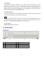
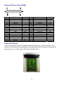
9. Connectors ........................................................................................................................... 37
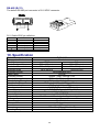
10. Specification....................................................................................................................... 39
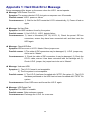
Appendix 1: Hard Disk Error Message ................................................................................... 40
Appendix 2: Supported HDD................................................................................................... 41
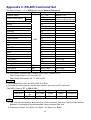
Appendix 3: RS-485 Command Set ........................................................................................ 42
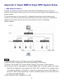
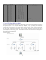
Appendix 4: Super MMX & Super MPX System Setup .......................................................... 43
4
1. Features
z
z
z
z
z
z
z
z
z
z
z
z
z
z
z
z
z
z
z
z
Powerful Wavelet compression
Proprietary real time O.S.
Duplex operation: View live and playback video simultaneously
Support NTSC and PAL system
Programmable recording picture rate (up to 60 PPS)
Recording priority of each camera dynamically adjusted by motion detection
Hot swappable HDD
Built in CD-RW for video clip export
Data format compatible with Windows
Powerful Alarm Processor allows flexible alarm trigger and response configuration
Programmable motion detection area and sensitivity for each camera individually
Different motion sensitivities available for day and night time
Intelligent algorithm refreshing main monitor display dynamically
User friendly video search
Versatile multiple-windows display format
Password to secure installation authorization
System auto reboot after power interruption
System software stored in nonvolatile memory, free from hard disk crash
P/ T/ Z control available
Remote monitoring and control through Internet or Ethernet (Optional)
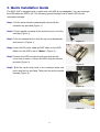
2. DVR-16/IP Application
DVR-16/IP is a cost-effective and easy-to-use multiplexed digital video recorder, equipped with
proprietary real time operating system, powerful Wavelet compression engine, duplex
multiplexer front-end, CD-RW and the hot swappable Hard Disc Drive.
5
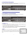
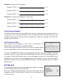
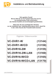
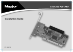
3. Quick Installation Guide
The DVR-16/IP is equipped with a mobile rack, the HDD is hot-swappable. You can exchange
the HDD when the HDD is full. The following figures illustrate how to install HDD into the
removable cartridge.
Step1: Pull the active-handle outwards and unlock with the
miniature key provided (Figure 1).
Step2: Pull the handle outwards till the carrier body is out of the
cartridge (Figure 1).
Step3: Push the release latch to slide the top cover backwards
and remove it (Figure 1).
<Figure 1>
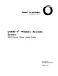
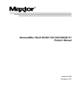
Step4: Insert the DC power cable and IDE cable on the HDD.
Make sure the HDD is set to “Master” (Figure 2).
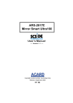
Step5: Position the HDD into carrier body and slide the top
cover back to secure. Secure the HDD using the screws
provided (Figure 3).
<Figure 2>
Step6: Slide the carrier body back in the cartridge frame and
lock it with the key provided. Then push the active-handle
inwards (Figure 4).
<Figure 3>
<Figure 4>
6
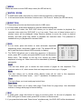
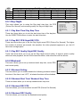
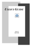
4. Front Panel Introduction
The DVR-16/IP front panel controls enable you to perform preset and programmable functions.
The figures below show the available buttons on the front panels.
**DVR-16/IP starts detecting the camera and recording automatically after power is on.
4.1 The Buttons on the Front Panel
The following are the introductions of DVR-16/IP front panel buttons. The front panel is
illustrated and each button is described by name and function.
CHANNEL 1~16
1. The number of channel buttons corresponds to the number of channels supported by the
unit. Press one of these buttons to view the channel full screen.
2. Press the number button corresponding to the wanted camera, and then press the SET
button to go to the “External Devices” Menu; you should go to the “Configuration Table 1”
first to set the correspondent dome’s “PTZ” item to enable.
GOTO
GOTO
In playback mode, you can press GOTO to enter GOTO menu. This
menu allows you to search for certain recorded video by date and
time, or you may either go to the beginning or the end of the recorded
video.
7
1 Minute
2 Hour
3 Day
4 Month
5 Year
5 Goto Begin
6 Goto End
7 Exit
30
20
21
11
02
MENU
Press this button to enter OSD setup menu (the LED will be lit).
ENTER / ZOOM
1. In OSD menu mode, this button is used to make the selection or save settings.
2. In full-screened mode, this button functions as a “2x2 Zoom In” button (the LED will be lit).
DIRECTION
1. These buttons function as directional control in OSD menu.
2. In Zoom mode, press these buttons to view the wanted viewing area.
3. In multi-window mode, the DVR-16/IP allows you to select one window to playback the
recorded video while the DVR-16/IP is in Live mode. Press one of these buttons and a
window cursor will be displayed. Using Direction buttons to move the cursor to desired
window, and then press Play button to playback the recorded video. The password is
needed before you playback the reocrded video.
SEQ
1. In Live mode, press this button to enter automatic sequential
sequencing mode, and press it again to exit. The button LED will
be lit (and also those channel LEDs currently in display).
2. The DVR-16/IP allows you to setup the sequence. In Sequence
mode, press SET to enter and press MODE to exit this Sequence
Setup menu. The number on the top is to remind you which
sequence is being set. Other items will be described by following
paragraphs.
Sequence_1 Set Up
1
2
3
4
5
6
7
8
9
10
Pages
Mode
Timer
Page 1
Page 2
Page 3
Page 4
Page 5
Page 6
Page 7
16
0
5
11
12
13
14
15
16
17
18
19
20
Page 8
Page 9
Page 10
Page 11
Page 12
Page 13
Page 14
Page 15
Page 16
Exit
Pages
This first item allows you to decide the total number of pages for this sequence. The
maximun value is 16, which means that each sequence can have up to 16 pages.
Mode
This item allows you to decide which display mode will be used in this sequence.
“0“ represents “full screen” mode, …and “7” represents 16-windows mode.
Timer
This item allows you to set each page’s dwell time.
Page Setup
These items allow you to setup each page. Press Enter for page setup. Use directional
buttons to change each page’s channel setting.
ESC
1. In OSD mode, press this button to return to previous menu. At the end of playback, the
DVR-16/IP goes to Pause mode; press ESC to return to Record mode.
2. If you press this button and “Down Arrow” simultaneously, the DVR-16/IP will be shutdowned.
8
SET
In multi-windows display mode, press this button to enter SET mode.
The menu will appear with the cursor over the first window. Use DIRECTION buttons to move
the cursor, then press the CHANNEL button to assign the camera directly. The cursor will move
to next window automatically. Press ESC button to exit SET mode.
MODE
Press this button to select display formats (4, 5, 7, 9,10,13 and 16 windows). The camera LEDs
of selected cameras should be lit.
FAST REWIND
In playback mode, press this button to play recorded video in reverse direction. Press it
repreatedly can change the rewind speed: x1, x2, x4 and x8. If the button has been pressed and
held for 3 seconds, the DVR-16/IP will go to the beginning of the recorded video.
PLAY
1. In Live mode, press this button to start playing back recorded video.
2. In Playback mode, press this button to stop playing (and the DVR-16/IP will start recording
automatically). When the DVR-16/IP has played back to the end of the video, it will pause on
the very last image ,and you can press ESC to leave the image and start recording again.
PAUSE
Press this button to pause playback video or to freeze live video. During this time of pause, the
pause LED would be lit.
FAST FORWARD
In playback mode, press this button to play recorded video in forward direction. Press it
repreatedly to increase the speed by x1 x2, x4 and x8. If the button has been pressed and held
for 3 seconds, the DVR-16/IP will go to the end of video.
9
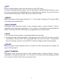
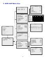
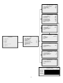
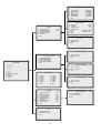
5. DVR-16/IP Menu Tree
Date / Time
Event List
1
2
3
02/10/21
02/10/21
02/10/22
15:58:53
18:24:30
10:19:16
OSD / Timer
1
2
3
4
5
6
7
8
9
10
11
1
2
3
4
5
6
7
8
9
MAIN MENU
1
2
3
4
5
6
7
8
9
10
11
Event List
OSD / Timer
Monitor
Camera
Record
Event
Others
Save / Load Default
CD-RW
Engineer
Exit
1
2
3
4
Date / Time
Date Display Mode
Date / Time Display
Date / Time Position
PB Date / Time Position
RS485 Time Calibration
Call Monitor Dwell
Text Color
Display Type
OSD
Exit
1 Year
2 Month
3 Day
4 Hour
5 Minute
6 Second
7 Week
8 Exit / Update
9 Exit / Without Update
1
M12
A3
L16
Configuration Table 1
Y/M/D
2Rows
5
7
1
T&D/T
3
Brightness
Contrast
Saturation
Hue
Live Refresh Rate
Screen Center Point
Background Color
Show Color Bar
Exit
125 IIIIIIIII
190 IIIIIIIII
188 IIIIIIIII
133 IIIIIIIII
Auto
Camera
4
2
Install
Covert
PT Z
2
V
.
.
3
V
.
.
4
V
.
.
5
V
.
.
6
V
.
.
7
V
.
.
8
V
.
.
9
V
.
.
10
V
.
.
11
V
.
.
12
V
.
.
13
V
.
.
14
V
.
.
15
V
.
.
16
V
.
.
Termination
Gain Control
Rec Priority
Alm Rec Prio
Call Seq
V
8
1
8
1
V
8
1
8
2
V
8
1
8
3
V
8
1
8
4
V
8
1
8
5
V
8
1
8
6
V
8
1
8
7
V
8
1
8
8
V
8
1
8
9
V
8
1
8
10
V
8
1
8
11
V
8
1
8
12
V
8
1
8
13
V
8
1
8
14
V
8
1
8
15
V
8
1
8
16
*
9
J
Y
j
y
+
:
K
Z
k
z
, _ .
: < >
L M N
[ \ ] ^
l m n
{ | }
Camera_1
! ” # $ % & ( )
0 1 2 3 4 5 6 7 8
@ A B C D E F G H I
P Q R S T U V W X
‘ a b c d e f g h i
p q r s t u v w x
Day / Night
1 Day / Night
2 Weekend
3 REC Event Only
4 REC Event At
5 Switch REC while PB
6 REC Priority Mode
7 Circular Record
8 HDD Full Alarm
9 Exit
5
OFF
Always
ON
Auto
ON
ON
1
2
3
4
5
6
7
Day Start Time
Day Stop Time
Day REC PPS
Day REC Quality
Night REC PPS
Night REC Quality
Exit
Weekend
1 Weekend Setting
2 Start
3 Stop
4 REC PPS
5 REC Quality
6 Exit
10
/
?
O
_
o
~
Camera 1
0000
Record
4-1
1
V
.
.
INPUT PASSWORD
1 Input Password
2 Enter Main Menu
3 Exit
2002
12
4
16
5
20
MON
2
Monitor
Configuration Table 1
Camera Detect
Camera Title
Exit
2-1
5-1
08:00
20:00
60
Super
60
Super
5-2
OFF
FRI
MON
60
Super
Day / Night Switch
6-1
No
Day
60
1 Day / Night SW Enable
2 Switch<OFF>
3 Delay For Active
4 Exit
Event Response
6-2
1 Internal Buzzer
2 Event Relay Output
3 Event List
4 Event Full Screen
5 Call Event Display
6 Response Duration
7 Any Key To Stop
8 Exit
ON
ON
ON
OFF
ON
10
ON
Motion Detect
1
2
3
4
6-3
Motion Detect
Configuration Table 2
Condition Set Up
Exit
OFF
Camera_1
MAIN MENU
1
2
3
4
5
6
7
8
9
10
11
Event List
OSD / Timer
Monitor
Camera
Record
Event
Others
Save / Load Default
CD-RW
Engineer
Exit
Event
1 Day / Night Switch
2 Event Response
3 Motion Detect
4 Alarm In
5 Video Loss Detect
6 Alarm Set / Reset SW
7 Release Time
8 Clear Event List
9 Exit
6
6-3-3
1 Select
2 Detect Area
3 Sensitivity
4 Exit
Camera 1
Dis
En
Alarm In
6-4
1 Alarm In Detect
2 Configuration Table 2
3 Exit
OFF
Release Time
6-7
1 Motion RES Time
2 Video Loss RES Time
3 Alarm In RES Time
4 Exit
2
2
10
Clear Event List
1
2
3
6-8
Clear Event List: No
Clear Event List: Yes
Exit
Configuration Table 2
Alm In Type
Day: Alm In
Day: Motion
Night: Alm In
Night: Motion
1
O
V
V
V
V
2
O
V
V
V
V
3
O
V
V
V
V
4
O
V
V
V
V
5
O
V
V
V
V
ESC For Return
11
6
O
V
V
V
V
7
O
V
V
V
V
8
O
V
V
V
V
9
O
V
V
V
V
10
O
V
V
V
V
6-4-2
11
O
V
V
V
V
12
O
V
V
V
V
13
O
V
V
V
V
14
O
V
V
V
V
15
O
V
V
V
V
16
O
V
V
V
V
Software Information
1 CPU Filename
2 FPGA Filename
3 Date
4 Video System
5 DSP BD HW
6 DSP BD SW
7 Exit
D6SE0100
FPGA0505
2003/01/23
NTSC
SK1V3302
SK1V3300
HDD Information
Others
7
1 RS-485 ID Setup
2 RS-485 Baud Rate
3 Software Information
4 HDD Information
5 Shutdown
6 Exit
224
9600
1 HDD Size
2 Free Size
3 Total Rec Time
4 Free Rec Time
5 Begin
6 End
7 Exit
7-3
7-4
40GB
17GB
7Hr
----Hr
2003/04/22 16:39
2003/04/23 11:12
Shutdown
7-5
1 Shutdown: No
2 Shutdown: Yes
3 Exit
Load Installer Setting
Save / Load Default
MAIN MENU
1
2
3
4
5
6
7
8
9
10
11
Event List
OSD / Timer
Monitor
Camera
Record
Event
Others
Save / Load Default
CD-RW
Engineer
Exit
1
2
3
4
5
8
Load Installer Setting
Save Installer Setting
Load Factory Setting
Load Factory Password
Exit
1
2
3
Save / Load: No
Save / Load: Yes
Exit
Save Installer Setting
1
2
3
CD-RW Copy
1
2
3
4
5
6
7
B_Year
B_Month
B_Day
B_Hour
B_Min
Play CD
Stop
8
9
10
11
12
13
14
Engineer
1
2
3
4
5
6
7
8
9
E_Year
E_Month
E_Day
E_Hour
E_Min
Copy
Exit
Save / Load: No
Save / Load: Yes
Exit
Load Factor Setting
1
2
3
10
9999
No
No
OFF
OFF
English
Exit
11
12
8-2
9
Change Password
Disable Password
Covert Cam Visible
Playback Check
Super MMX Mode
Language
Format Hard Disk
System Color
Exit
1 Set Up Data: Save
2 Set Up Data: Cancel
3 Exit
8-1
Color
Save / Load: No
Save / Load: Yes
Exit
Format Hard Disk
1
2
3
8-3
Format Hard Disk: 1
Format Hard Disk: 2
Exit
9-5
6. OSD Menu Setup
The OSD menu is composed in hierarchy architecture, it allows you to
configure the DVR-16/IP according to the applictation enveironment.
Many options can be selected via the operation of the OSD menu.
To enter this OSD menu, press the MENU button of the front panel,
then the OSD menu will appear with a highlight cursor over the first
item. The cursor can be moved by the up and down buttons.
If you want to exit the OSD menu, you may either 1)select the last
item “EXIT” and then press ENTER button; or 2)press ESC button of
the front panel directly.
MAIN MENU
1 Event List
2 OSD / Timer
3 Monitor
4 Camera
5 Record
6 Event
7 Others
8 Save / Load Default
9 Engineer
10 Engineer
11 Exit
6.1 Event List
Event List
The item allows you to enter the Event List. Up to 255 events will be
logged using non-volatile memory. The memory architectrue is “First
In First Out”, so always the latest events remain on the list.
1
2
3
02/10/20
02/10/22
02/10/22
08:12:39
12:38:21
15:58:53
L16
A3
M12
---Continue---
OSD / Timer
6.2 OSD/ Timer
This menu allows you to set the current date/ time, and other
On-Screen-Display (OSD) parameters. You can press the ENTER
button to enter the sub-menu.
1 Date/ time
2 Date Display Mode
3 Date/ Time Display
4 Date/ Time Position
5 RS485 Time Calibration
6 Call monitor Dwell
7 Text Color
8 Display Type
9 OSD Display
10 Exit
Y/M/D
2 Rows
5
7
1
T&D/T
6.2.1 Date/ Time
Item 1~7 allow you to set the date and time, use the right/ left buttons
to adjust the DVR-16/IP to local time.
If you want to save the modification(s), move the cursor to 8 Exit/
Update and press Enter button, the adjusted setting(s) will be
memorized. If you don’t want to save the modifications, move the
cursor to 9 Exit / Without Update and press Enter button, the adjusted
setting(s) will be discarded.
Date / Time
1 Year
2 Month
3 Day
4 Hour
5 Minute
6 Second
7 Week
8 Exit / Update
9 Exit / Without Update
2002
12
4
16
5
20
MON
6.2.2 Date Display Mode
This item allows you to select a format of date OSD display. You can use right/ left buttons to
choose the select from: Y/M/D, M/D/Y and D/M/Y.
6.2.3 Date/ Time Display
This item allows you to select one or two rows for Date /time OSD display.
13
6.2.4 Date/ Time Position
This item allows you to move current Date/ Time Display to any position. Use the DIRECTION
buttons to move Date/ Time display.
6.2.5 PB Date/ Time Position
This item allows you to move the recorded Date/ Time Display to any position.
6.2.6 RS-485 Time Calibration
RS-485 is used for multi-point communications: many devices can be connected to the same
bus. Move to this item and press the ETNER button, all DVR-16/IP timers will be synchronized.
6.2.7 Call Monitor Dwell
The call monitor is always switching full screen video of all installed cameras, this item allows
you to set the Dwell Time between switching. The timer value ranges from 1 to 255 (the unit is
second).
6.2.8 Text Color
This item allows you to select one from 16 different colors for all display on the screen.
6.2.9 Display Type
This item allows you to select one from 6 different text types (reverse, bold…) for on Date/ Time
display.
6.2.10 OSD
This item allows you to select which information you want to display; you can choose from
1)T&D/T(camera title and date/time); 2)Title; 3)D/T(date/time); 4)OFF.
6.3.Monitor
This menu allows you to adjust the quality of the displayed image.
Monitor
1 Brightness
2 Contrast
3 Saturation
4 Hue
5 Live Refresh Rate
6 Screen Center Point
7 Screen H-Size
8 Background Color
9 Show Color Bar
10 Exit
125IIIIIIII
190IIIIIIII
188IIIIIIII
133IIIIIIII
Auto
6.3.1 Video Setup
Item 1~4 involve adjusting the brightness, contrast, saturation and hue of attached cameras.
You may use the right/ left DIRECTION buttons to adjust the value.
14
2
6.3.2 Live Refresch Rate
This item allows you to setup the camera refresh rate on the Main monitor; use right/ left buttons
to select “Fix” or “Auto”. “Fix” means each camera has the same refresh rate. “Auto” means the
camera with more motion will get higher refresh rate automatically.
6.3.3 Screen Center Point
This item allows you to move the center point of the main monitor. Use the DIRECTION buttons
to pan/ tilt the monitor center point. Press ESC button to exit when finished.
6.3.4 Background Color
This item allows you to select 1 from 16 different colors for the background color of 1) video-loss,
2) camera un-installed and 3) covert situations.
6.3.5 Show Color Bar
This function allows you to fine tune the monitor’s performance using color bar pattern
generated by the DVR-16/IP.
6.4 Camera
This menu allows you to adjust camera-related items, ex. Camera title,
Power On Detect, etc.
Camera
1 Configuration Table 1
2 Camera Detect
3 Camera Title
4 Title Position
5 Exit
6.4.1 Configuration Table 1
Configuration Table 1 allows you to configure 5 parameters for each camera individually.
Configuration Table 1
Install
Covert
PTZ
Termination
Gain Control
REC Priority
Alm REC Prio
Call Seq
1
V
·
·
V
8
1
8
1
2
V
·
·
V
8
1
8
2
3
V
·
·
V
8
1
8
3
4
V
·
·
V
8
1
8
4
5
V
·
·
V
8
1
8
5
6
V
·
·
V
8
1
8
6
7
V
·
·
V
8
1
8
7
8
V
·
·
V
8
1
8
8
ESC For Return
15
9
V
·
·
V
8
1
8
9
10 11 12 13 14 15 16
V V V V V V V
·
·
·
·
·
·
·
·
·
·
·
·
·
·
V V V V V V V
8 8 8 8 8 8 8
1 1 1 1 1 1 1
8 8 8 8 8 8 8
10 11 12 13 14 15 16
Default
6.4.1.1 Install
This item allows you to install each channel on 1 Configuration Table1. Every channel is
“installed” by default; you may uninstall any one of them manually. Once a channel is
un-installed, all related functions are disabled (√ = camera installed; • = camera not installed).
6.4.1.2 Covert
This item allows you to make each camera’s input invisible (covert) on both main and call
monitor, while DVR-16/IP keeps recording the camera’s video. The default setting is every
camera visible (√ = covert; • = not covert).
6.4.1.3 PTZ
Set this item to enable, users can set the following external device
OSD settings through the DVR-16/IP front panel. Press the number
button corresponding to the wanted camera to make it full screen, and
then press the SET button to go to the “External Devices” Menu.
◆ RS-485 Baud Rate
◆
External Devices
1 RS-485 Baud Rate
2 DSCP Speed Dome
3 CHIPER CRT.V9KRP
4 PELCO Speed Dome
5 Exit
Baud rate is a number related to the speed of data transmission in your security
system. The higher the baud rate, the more bits per second that are transferred.
Before the data are transferred between two devices, you must ensure that both
devices are configured to the same transmission rate.
DSCP Speed Dome
DSCP Speed Dome
This sub-menu is offered to adjust the dome settings. After
you are in the sub-menu, you can pan/ tilt the speed dome
freely by pressing SET and the direction buttons
simultaneously.
1 RS-485 ID Setup
2 Zoom
3 Brightness
4 Set Preset Point
5 Enter Speed Dome Menu
6 Exit
XXX
XXX
RS-485 ID Setup
If you want to control the DSCP Speed Dome through the front panel, you should
firstly check and modify the RS-485 ID here.
Zoom
Press the Enter button to enter the Zoom mode. You can simply push the right
direction button to zoom in (tele) and the left direction button to zoom out (wide).
Press the ESC button to exit the Zoom mode.
Brightness
Use the right and left direction buttons to adjust the brightness of the selected
dome camera. Press the ESC button to exit.
Set Preset Point
This item allows you to set the preset points. Pan/ Tilt the dome camera to the
wanted position and give the preset point a number, and then press the Enter
button.
Enter Speed Dome Menu
Press Enter on this item to go to the OSD menu of installed Speed Dome.
16
◆
PELCO Speed Dome
PELCO Speed Dome
DVR-16/IP is capable of connecting to PELCO Speed Dome;
the related settings can be adjusted here in this sub-menu.
You can pan/ tilt PELCO Speed Dome by pressing SET and
the direction buttons simultaneously after you are entering
this sub-menu.
1 Protocol Setup
2 ID Setup
3 Zoom
4 Focus
5 Bfightness
6 Set Preset Point
7 Goto Preset Point
8 Enter Speed Dome Menu
9 Exit
D_Type
1
Protocol Setup
There are two Protocol types to choose from: D_type and P_type.
ID Setup
Each PELCO dome camera should have a ID individually.
Zoom
Press the right direction to zoom in (tele) and the left direction button to zoom out
(wide). Press ESC to exit the zoom mode.
Focus
Press the right/ left direction to change focus back and forth between a near object
and a far object. Press ESC to exit the mode.
Brightness
Use the right and left direction buttons to adjust to appropriate brightness. Press
ESC to exit when you finish the setting.
Set Preset Point
This item allows you to set preset points through the front panel. Pan/ tilt the
connected receiver to a proper position, and then press the number buttons to
assign a number to the preset point. Press Enter to finish the setting.
Goto Preset Point
Press right/ left direction button to select the number of the wanted preset point;
then press Enter to go to the selected preset point.
◆
Enter Speed Dome Menu
Press Enter on this item to enter connected PELCO dome camera’s OSD menu.
The function only supports a dome camera with DSCP protocol.
CHIPER CRT.V9KRP
CHIPER CRT.V9KRP
This sub-menu allows you to set the receiver. In the
sub-menu, you can pan/ tile the receiver by pressing SET
and direction buttons simultaneously.
Item 1~4 (ID Setup, Zoom, Focus, Brightness)
Please refer to the receiver user’s manual for detailed
information.
1 ID Setup
2 Zoom
3 Focus
4 Brightness
5 Set Preset Point
6 Goto Preset Point
7 Set Group Dwell
8 Go Preset Group
9 Stop Preset Group
10 Exit
Set Preset Point
This item allows you to set preset points through the front panel. Pan/ tilt the
connected receiver to a proper position, and then press the number buttons to
assign a number to the preset point. Press Enter to finish the setting.
17
1
1
Goto Preset Point
Press right/ left direction button to select the number of the wanted preset point;
then press Enter to go to the selected preset point.
Set Group Dwell
Press the right/ left direction button to choose a proper dwell time.
Go Preset Group
Press Enter to start sequencing.
Stop Preset Group
Press Enter to stop sequencing.
6.4.1.4 Termination
This item allows you to enable/ disable the terminal resister of each camera. If the camera
loop-back connector is not used, the terminal resister should be enabled to get correct signal
termination; this is the default condition. Otherwise, the terminal resister should be disabled (√ =
Terminal resister is enabled; • = Terminal resister is disabled).
6.4.1.5 Gain Control
This item allows you to adjust the camera’s video level. You may adjust the value between 1
and 16 for each camera.
6.4.1.6 REC Priority
This item allows the user to set the recording priority for each camera under normal state (No
alarm occurred). The DVR-16/IP will record the camera that is assigned with a higher priority
more frequently.
The user can move the cursor and use ENTER key to adjust the value. The value ranges from 1
to 16; “1” stands for the lowest priority; “16” stands for the highest priority. If the camera is not
installed, the priority will be set to 0 automatically.
6.4.1.7 Alarm REC Priority
This item allows you to set the recording priority when an alarm is triggered for the current
channel, either by Alarm In or by Motion.
6.4.1.8 Call Seq
For Call monitor, there are 16 steps programmable. This item allows you to assign camera for
each step (1~16); “0” means to skip this step. Those cameras which are not installed or
converted won’t be displayed on call monitor.
Example:
If you set the PPS to “30”, the record priority of channel to level ”4”, and the record priority of all
rest channels to level “1’, then each channel’s PPS can be count by below formula.
18
Situation 1: No alarm event happens.
Channel 1 PPS = 30 *
4
= 6.31
4 +1+1+1+1+1+1+1+1+1+1+1+1+1+1+1
Channel 2 PPS = 30 *
1
= 1.58
4 +1+1+1+1+1+1+1+1+1+1+1+1+1+1+1
Channel 3 PPS = 30 *
1
= 1.58
4 +1+1+1+1+1+1+1+1+1+1+1+1+1+1+1
Situation 2: An alarm event happens on channel 2.
Channel 1 PPS = 30 *
4
= 4.61
4 + 8 +1+1+1+1+1+1+1+1+1+1+1+1+1+1
Channel 2 PPS = 30 *
8
= 9.23
4 + 8 +1+1+1+1+1+1+1+1+1+1+1+1+1+1
Channel 3 PPS = 30 *
1
= 1.15
4 + 8 +1+1+1+1+1+1+1+1+1+1+1+1+1+1
6.4.2 Camera Detect
The DVR-16/IP can check the camera BNC connectors for video signal and judge the channel is
connected or not. If the camera doesn’t exist, it’s recommended to set that channel as “not
installed”. Otherwise that channel will be considered as “video loss”. Besides, the DVR-16/IP
storage space is wasted.
6.4.3 Camera Title
Each camera can be assigned a “Title” (up to 12 characters). The
default title for each camera is the channel number.
Use the right and left direction buttons to select the wanted camera,
and then press Enter to enter a virtual table (shown as right figure).
Camera_1
! ” # $ % & ( )
0 1 2 3 4 5 6 7 8
@ A B C D E F G H I
P Q R S T U V W X
‘ a b c d e f g h i
p q r s t u v w x
*
9
J
Y
j
y
+
:
K
Z
k
z
, _ .
: < >
L M N
[ \ ] ^
l m n
{ | }
You can use DIRECTION buttons to select wanted character, and press ENTER to add the
character to the title. You can also press MODE button to correct the wrong character you enter
by mistake. Press MODE button, and a cursor will appear over the title. Press MODE button
repeatedly till the cursor over the character need to be changed; now you can pick another
character to replace it by using the DIRECTION buttons. The first character (blank) is used as
Space button.
6.5 Record
This menu allows you to set up all the parameters related to recording,
ex. REC Quality, PPS (Picture Per Second)…
Once you change these parameters, the total record time will be
changed as well. The table below is offered for your reference (the
PPS is set to 60).
19
Record
1 Day / Night
2 Weekend
3 REC Event Only
4 REC Priority Mode
5 Circular Record
6 HDD Full Alarm Out
7 Exit
OFF
OFF
ON
/
?
O
_
o
~
HDD
size
40 GB
80 GB
120 GB
160 GB
Quality: Ultra
5
10
15
20
Total Record Time (Hour)
Quality: Super Quality: High Quality: Normal
7
9
12
14
18
24
21
27
36
28
36
48
6.5.1 Day/ Night
Quality: Low
15
30
45
60
Day / Night
This menu allows you to setup the Day start/ stop time, the PPS
(Picture Per Second) and recording quality for Day and Night time.
6.5.1.1 Day Start Time/ Day Stop Time
1 Day Start Time
2 Day Stop Time
3 Day REC PPS
4 Day REC Quality
5 Night REC PPS
6 Night REC Quality
7 Exit
08:00
18:00
60
Super
60
Super
These two items allow you to set the start/ stop time of the daytime.
Use the DIRECTION buttons to enter the start/ stop time.
6.5.1.2 Day REC PPS/ Night REC PPS
These two items allow you to set the Day/ Night record PPS (Picture Per Second). The higher
the number of pictures per second, the smoother the video playback appears to you, but it’ll
take more storage space.
6.5.1.3 Day REC Quality/ Night REC Quality
These two items allow you to set up the Day/ Night record quality. A superior picture quality
affects a better playback, but will fill the hard disk faster; total record time will be shorter.
6.5.2 Weekend
This menu allows you to set up weekend start/ stop time, record PPS
and record quality.
6.5.2.1 Weekend Setting
This item allows you to enable/ disable the following weekend-related
functions. If the item is set “OFF”, all related functions will be disabled.
6.5.2.2 Weekend Start Time/ Weekend Stop Time
These two items allow you to set up weekend start/ stop time.
6.5.2.3 Weekend REC PPS
This item allows you to set weekend record PPS (Picture Per Second).
6.5.2.4 Weekend REC Quality
This item allows you to set up the weekend record quality
20
Weekend
1 Weekend Setting
2 Start
3 Stop
4 REC PPS
5 REC Quality
6 Exit
OFF
FRI
MON
60
Super
6.5.3 REC Event Only
You are allowed to decide the situation DVR-16/IP starts recording. If you select “OFF”, then
DVR-16/IP will remain in recording mode all the time. If you choose a time, then DVR-16/IP
starts recording only when an event (both Alarm and Motion events) is triggered, and the time
you choose indicates how long DVR-16/IP keeps recording. For example, if you select “15 sec”,
DVR-16/IP starts recording when an event is triggered, and it keeps recording for 15 seconds.
6.5.4 REC Event At
The DVR-16/IP allows you to record event recording only. In this case, you can decide the
recording duration: Always, Night, Day and Weekend. If “Weekend” is selected (the “Weekend
setting” must be “ON”), then the DVR-16/IP records event recording only on weekends; and if
“always” is selected, the DVR-16/IP won’t record image until an event is triggered all the time.
Record Event Only
Option 1: OFF
Option 2: 15 Sec
Option 3: 30 Sec
Option 4: 45 Sec
Option 5: 1 Min
Option 6: 3 Min
Option 7: 5 Min
Option 8: 10 Min
Option 9: 20 Min
Option 10: 30 Min
Record Event At
Recording Status
Option 1: Always
Option 2: Day
Option 3: Night
Option 4: Weekend
Recording Mode
Normal Status (Non-recording Mode)
6.5.5 Switch REC While PB
If an event is triggered while you are playing back the video, the DVR-16/IP can switch back to
recording image automatically to alert you to the event. If you choose “ON”, the DVR-16/IP will
switch back to the recording image while the event is triggered.
21
6.5.6 Rec Priority Mode
This item allows you to set up the record priority, use RIGHT/LEFT keys to select Setup or Auto.
Setup means priority mode will follow the setup value in configuration table, Auto means the
camera with most motion will get higher priority automatically.
6.5.7 Circular Record
The DVR-16/IP can store the recorded video information in circular or not. If the setting is “ON”
(default), the earliest recorded video will be over-written automatically (none-stop recording).
If Circular Record setting is “OFF”, the recording will be stopped when the HDD is full; under this
situation, a flash highlighted message (HDD Full) will be shown on the screen when the rest
recording time is about 45 minutes; and the beeper will start beeping when the rest recording
time is about 15 minutes.
6.5.8 HDD Full Alarm
If you select “ON” for this item, the beeper will start beeping when the rest recording time is
about 15 minutes; and the beeper will stop beeping after you insert a new HDD.
The other way to stop the beeper is to select “OFF” for this item.
6.6 Event
Event
This menu allows you to configure how the EVENT condition is
handled and how the DVR-16/IP responses.
When an alarm is triggered, you can press the ESC button and the
alarm channel button to switch the call monitor to the alarm channel;
after then, you can press these two buttons to start switching again.
6.6.1 Day/ Night Switch
1 Day / Night Switch
2 Event Response
3 Motion Detect
4 Alarm In
5 Video Loss Detect
6 Alarm Set / Reset SW
7 Release Time
8 Clear Event List
9 Exit
Dis
En
Day/ Night Switch
This sub-menu allows you to enable or disable the “Day/ Night Switch”
signal from the external I/O connector. Move to 1 Day/ Night Switch
and press ENTER button, the sub-menu will appear.
1 Day / Night SW Enable
2 Switch <OFF>
3 Delay For Active
4 Exit
No
Day
60
6.6.1.1 Day/ Night SW Enable
Use right/ left buttons to select YES (enable) or NO (disable). If you select “NO”, the Day/ Night
Switch signal will be ignored; the event processor will follow the time schedule that defined in
Record Section. If you select “YES”, the event processor will follow the On/ Off position of the
external Day/ Night switch.
6.6.1.2 Switch <OFF>
This item allows you to configure which setting (Day/ Night) will be activated when the switch is
OFF. You may select Day or Night by using the right/ left buttons.
22
6.6.1.3 Delay For Active
After the Day/ Night switch setting has changed, there is a delay time before the event process
takes effect; this function is to avoid the operator triggering a false event by mistake.
6.6.2 Event Response
Event Response
This sub-menu allows you to set how the DVR-16/IP responds to the
triggered event.
1 Internal Buzzer
2 Event Relay Output
3 Event List
4 Event Full Screen
5 Call Event Display
6 Response Duration
7 Any Key To Stop
8 Exit
ON
ON
ON
OFF
ON
10
ON
6.6.2.1 Internal Buzzer
This item allows you to set the internal buzzer activated or not when an event is triggered.
6.6.2.2 Event Relay Output
There are two alarm output signals in the external I/O connector: Alarm N.O. (normal open) and
Alarm N.C. (normal close), these signals are driven by an on-board relay. These signals can be
used to drive a light or siren to warn the operator of alarm events.
This item allows you to enable/ disable the alarm output pins. If the alarm output is OFF
(disabled), the relay won’t be energized when alarm is triggered.
6.6.2.3 Event List
The events will be logged in the non-volatile memory.
The first column is the item number, followed by the date and time of the event and the “type of
event”: “A” represents Alarm Input, “L” represents Video Loss, and “M” represents Motion
Detection. The last column is the channel number of the event.
6.6.2.4 Event Full Screen
When event is occurred on any camera input, the video of this camera would be displayed on
the main monitor in full screen, and keep until event duration time is expired. This item allows
you to enable/ disable the function.
6.6.2.5 Call Event Display
If you select “YES” for this item, The Call Monitor will switch to the corresponded camera
immediately when an event is triggered. Otherwise, the Call Monitor just switches between each
installed camera sequentially.
6.6.2.6 Response Duration
This item allows you to decide how long time the buzzer and Alarm Out relay keeps after an
event is triggered. You can choose the alarm output from 1 second to 9999 seconds.
23
6.6.2.7 Any Key To Stop
When the event is triggered, the buzzer will beep, the Alarm Out relay will be activated. If you
want to stop these actions by pressing any one key, then you must select “YES” for this item.
6.6.3 Motion Detect
Motion Detect
This menu allows you to configure how Motion Detection works. Each
camera can have its “Detect Area” and “Sensitivity” defined
individually.
1 Motion Detect
2 Configuration Table 2
3 Condition Set Up
4 Exit
OFF
6.6.3.1 Motion Detect
This item allows you to enable/ disable the motion detect function of the DVR-16/IP.
6.6.3.2 Configuration Table 2
Move the cursor to 2 Configuration Table 2 and press ENTER button, the table will appear.
This table allows you to enable/ disable the day and night motion detect functions.
Alm In Type
Day: Alm In
Day: Motion
Night: Alm In
Night: Motion
1
O
√
√
√
√
2
O
√
√
√
√
3
O
√
√
√
√
4
O
√
√
√
√
5
O
√
√
√
√
Configuration Table 2
6
7
8
9 10 11
O O O O O O
√
√
√
√
√
√
√
√
√
√
√
√
√
√
√
√
√
√
√
√
√
√
√
√
12
O
√
√
√
√
13
O
√
√
√
√
14
O
√
√
√
√
15
O
√
√
√
√
16
O
√
√
√
√
ESC For Return
6.6.3.3 Condition Set Up
This menu allows you to setup each camera’s motion detected area
and sensitivity.
First select the wanted camera by using the right and left direction
buttons, and then move the cursor to the second and third items to
setup the chosen camera’s detect area and sensitivity.
6.6.3.4 Detect Area
Camera_1
1 Select
2 Detect Area
3 Sensitivity
4 Exit
Camera 1
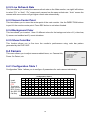
◎◎◎◎◎◎◎◎◎◎◎◎◎◎◎◎
This item allows you to setup the motion detect area of each camera.
The screen is covered by 192 (16x12) “detection grids”.
You may use the DIRECTION buttons to move the cursor then press
the ENTER button to enable/ disable the grids. Pressing MODE button
can change the size of the cursor. You may also toggle all the grids
on/off by pressing SET button (◎: disabled; ◎ : enabled).
◎◎◎◎◎◎◎◎◎◎◎◎◎◎◎◎
◎ ◎
◎ ◎ ◎ ◎ ◎ ◎ ◎ ◎ ◎ ◎ ◎ ◎
◎ ◎
◎ ◎
◎ ◎ ◎ ◎ ◎ ◎ ◎ ◎ ◎ ◎ ◎ ◎
◎ ◎
◎ ◎
◎ ◎ ◎ ◎ ◎ ◎ ◎ ◎ ◎ ◎ ◎ ◎
◎ ◎
◎ ◎
◎ ◎ ◎ ◎ ◎ ◎ ◎ ◎ ◎ ◎ ◎ ◎
◎ ◎
◎ ◎
◎ ◎ ◎ ◎ ◎ ◎ ◎ ◎ ◎ ◎ ◎ ◎
◎ ◎
◎ ◎
◎ ◎ ◎ ◎ ◎ ◎ ◎ ◎ ◎ ◎ ◎ ◎
◎ ◎
◎ ◎
◎ ◎ ◎ ◎ ◎ ◎ ◎ ◎ ◎ ◎ ◎ ◎
◎ ◎
◎ ◎
◎ ◎ ◎ ◎ ◎ ◎ ◎ ◎ ◎ ◎ ◎ ◎
◎ ◎
◎ ◎
◎ ◎ ◎ ◎ ◎ ◎ ◎ ◎ ◎ ◎ ◎ ◎
◎ ◎
◎◎◎◎◎◎◎◎◎◎◎◎◎◎◎◎
◎◎◎◎◎◎◎◎◎◎◎◎◎◎◎◎
24
6.6.3.5 Sensetivity
This item allows you to setup the threshold of motion detection.
The first bar shows the current detected amount of motion of this
camera. The second and third bar allows you to setup the “day/ night
threshold” (or “trigger level”), once the detected motion amount
become larger than this level; the alarm will be triggered.
6.6.4 Alarm In
This menu allows you to enable/ disable the Alarm pins of external I/O
connector and to select N.O. (normal open) or N.C. (normal close)
type for each pin.
Motion Detect
Threshold: Day
Threshold: Night
Alarm In
1 Alarm In Detect
2 Configuration Table 2
3 Exit
OFF
6.6.4.1 Alarm In Detect
This item allows you to enable (YES) or disable (NO) the Alarm In pins.
6.6.4.2 Configuration Table 2
This item allows you to select N.O. (normal open) or N.C. (normal close) type for each Alarm In
pins.
6.6.5 Video Loss Detect
This item allows you to enable/ disable the DVR-16/IP to detect Video Loss as an alarm event.
6.6.6 Alarm Set/ Reset SW
This item allows you to enable/ disable the Alarm Set/ Reset signal of the external connector. If
you select EN (enable), then you can force the alarm output to on/ off by using Alarm Set signal.
6.6.7 Release Time
This menu allows you to set the “release time” of alarm source: motion
detection, video loss and alarm in. The release time defines how long
time after the alarm trigger condition disappears; the same condition
should be ignored to avoid false alarm being re-triggered.
6.6.8 Clear Event List
This menu allows you to clear event list. If you want to delete the
event list, move your cursor to 2 Clear Event List: YES. If you want to
keep the event list, move your cursor to 1 Clear Event List: NO.
This arrangement is to avoid user clear the list by mistake.
25
Release Time
1 Motion RES Time
2 Video Loss RES Time
3 Alarm In RES Time
4 Exit
Clear Event List
1 Clear Event List: No
2 Clear Event List: Yes
3 Exit
2
2
10
6.7 Others
This menu allows you to check the RS485 communication protocol
and software version.
Others
1 RS-485 ID Setup
2 RS- 485 Protocol
3 Software Information
4 HDD Information
5 Shutdown
6 Exit
224
6.7.1 RS-485 ID Set Up
This item can only be accessed by the installer, the RS-485 ID address of this DVR-16/IP can
be modified here.
6.7.2 RS-485 Baud Rate
You can choose the baud rate form 38400, 19200, 9600, 4800 and 2400.
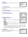
6.7.3 Software Information
Software Information
This menu presents the software information.
1 CPU Filename
2 FPGA Filename
3 Date
4 Video System
5 DSP BD HW
5 DSP BD SW
6 Exit
D6SE0100
FPGA0505
2002/01/23
NTSC
SK1V3302
SK1V3300
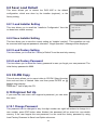
6.7.4 HDD Information
This item shows you the HDD information.
HDD Information
HDD Size
The item shows how large size the current HDD has for saving
video files.
Free Size
It shows how much available space the current HDD leaves.
1 HDD Size
2 Free Size
3 Total Rec Time
4 Free Rec Time
5 Begin
6 End
7 Exit
7-4
40GB
17GB
7Hr
----Hr
2003/04/22 16:39
2003/04/23 11:12
Total Rec Time
It shows how much time the current HDD originally can provide for saving the video files.
Free Rec Time
It shows how much time the current HDD can save video files. If the DVR is set to record
in linear mode (the system will not overwrite files when the HDD is full), the available
recording time will be calculated and shown on the screen automatically; or, if the DVR is
set to circular mode, the OSD display on the screen will be “- - - - Hr”.
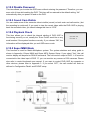
6.7.5 Shutdown
Shutdown
This item allows you to shutdown the DVR-16/IP.
There is the other way to shutdown the DVR-16/IP: press ESC and
Down Arrow buttons simultaneously.
26
1 Shutdown: No
2 Shutdown: Yes
3 Exit
6.8 Save/ Load Default
Save/ Load Default
This menu allows you to restore the DVR-16/IP to the default
configuration, which was done by the installer (engineer), or the
factory setting.
6.8.1 Load Installer Setting
This item allows you to recall the “Installer’s Configuration” from the
on-board non-volatile memory.
1 Load Installer Setting
2 Save Installer Setting
3 Load Factory Setting
4 Load Factory Password
5 Exit
Load Installer Setting
1 Save/ Load: No
2 Save/ Load: Yes
3 Exit
6.8.2 Save Installer Setting
This item allows you to save the current setting as “Installer’s setting”. This operation can only
be executed with engineer password; otherwise, “Illegal Operation” message will be displayed.
6.8.3 Load Factory Setting
This item allows you to recall the “Factory’s Default” from the read only memory.
6.8.4 Load Factory Password
This item allows you to reload the factory password in case you forget your own password. The
initial factory password is 9999.
6.9 CD-RW Copy
CD-RW Copy
This sub-menu allows you to export video to CD-RW. Select the start
time and end time of desired video and then press ENTER on 13
Copy to start copying.
Press the 6th item to play the CD.
6.10 Engineer Set Up
1 B_Year
2 B-Month
3 B-Day
4 B_Hour
5 B_Min
6 Play CD
7 Stop
8 E_Year
9 E_ Month
10 E_Day
11 E_Hour
12 E_Min
13 Copy
14 Exit
Engineer Set Up
If you enter the main menu with engineer’s password, you can enter
this menu.
1 Change Password
2 Covert Cam Visible
3 Playback Check
4 Language
5 Format Hard Disk
6 Exit
9999
Yes
OFF
English
6.10.1 Change Password
This password can be changed to any four-digit number use right/ left buttons to change to a
new number, press ESC button when finished, the password will be saved into non-volatile
memory. If the user forgets this new password, he can recall the factory password by using
Load Factory Password in Save Load Option sub-menu.
27
6.10.2 Disable Password
This item allows you to enter the OSD menu without entering the password. Therefore, you can
save a lot of time while setting the DVR. This item will be restored to the default setting “No”
automatically after you power off and on the DVR.
6.10.3 Covert Cam Visible
You can make some of the camera’s video invisible (covert) on both main and call monitor, (but
the recording is continued); if you want to view the covert video while the DVR-16/IP is playing
back the recorded video, you should change this item to “YES”.
6.10.4 Playback Check
This item allows you to check the internal cabling of DVR-16/IP is
functioning correctly or not, usually the “Error Fields” would be a very
small number if the system functions correctly. If you choose “ON”, the
information will be displayed after you exit OSD menu mode.
Input Fields: 2623
Error Fields: 13
6.10.5 Super MMX Mode
This function is used for Matrix-Multiplexer system. The system skeleton and setup guide is
shown in Appendix 4 Super MMX and Super MPX System Setup. If you select “Yes”, the call
monitor display will depend on RS-485 command. The call monitor output of DVR 1~16 must be
connected to the video input of DVR 17; you can monitor any camera of 256 cameras. Please
also refer to control keyboard user manual. If you want to control DVR-16/IP by computer or
other devices, please refer to Appendix 3. If you select ‘OFF’, the call monitor will work as
defined in Configuration Table1 and EVENT setup.
28
6.10.6 Language
This item allows you to select your native language.
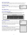
6.10.7 Format Hard Disk
This item allows you to format the HDDs. Choose the HDD you want
and then press ENTER to format the selected HDD.
Before you use a new HDD, you should insert it to DVR-16/IP to
format to FAT32. And if the HDD was used in anther machine with
another kind of file system, therefore, the HDD must be formatted to
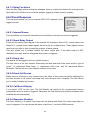
FAT32 in DVR-16/IP before recording process.
Format Disk
1 Format Hard Disk 1
2 Format Hard Disk 2
3 Exit
6.10.8 System Color
This item allows you to choose “Color” or “Mono”
6.11 Exit
If you move the cursor to first item and press ENTER, the
Exit
modifications you have made will be saved into the non-volatile
1 Set Up Data: Save
2 Set Up Data: Cancel
memory (EEPROM).
3 Exit
If you move the flashing highlight to the second item and press
ENTER; or press ESC button on the front panel, the modification you
have made will keep affective, but not saved into EEPROM. Therefore,
if you power OFF and ON the DVR-16/IP, the modifications will be canceled.
7. Windows Application Software
The file format of DVR-16/IP is compatible with Windows O.S; you can process recorded video
data under Windows 98, 2000 and XP systems. The application software allows you to playback,
printout, export JPEG file or clip a segment of video.
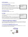
7.1 Connect the USB Mobile Rack to PC
Move out the HDD Cartridge form DVR-16/IP and insert it to a “USB Mobile Rack”, then connect
the “USB Mobile Rack” and PC with a USB Cable.
29
7.2 Download the Software
To process recorded video on your computer, you need to download DVR Windows application
software first. After Window AP has been installed, you can now connect the swappable HDD to
your computer and process the recorded video.
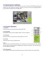
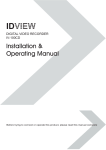
7.3 Function Buttons
1. Open File
Press this button to search and open recorded video file.
1
3
2. Display Mode
Press these buttons to choose display mode (4, 9 and 16 windows).
4
5
3. Save Image
Press this button for saving current image (JPEG) on your P.C.
6
4. Print Out
Press this button to print out single picture.
5. Set
Press this button to start setting windows. Use the Mouse to move the cursor to certain window,
and then press a Channel button for assigning the camera to this window. The cursor will move
to next window automatically.
6. File Information
The Information of the opened file will be shown here: File Name, Start Time and End Time.
30
2
7
8
9
10
11
12
13
14
15
16
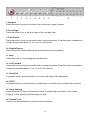
7. Playback
Press this button to play the recorded video, and press it again to pause.
8. Go to Begin
Press this button to go to the first image of the recorded video.
9. Fast Rewind
Press this button to play the recorded video in reverse direction. Press this button repeatedly to
change the playback speed: x1, x4, x8, x16, x32 and x64.
10. Rewind Playing
Press this button to rewind playing the recorded video at normal speed.
11. Stop
Press this button to stop playing the recorded video.
12. Fast Forward
Press this button to play the recorded video in forward direction. Press this button repeatedly to
change the playback speed: x1, x4, x8, x16, x32, and x64.
13. Go to End
In playback mode, press this button to go to the end image of the opened file.
14. GOTO
In playback mode, press this button for searching the recorded video of certain date and time.
15. Video Clipping
Press this button to clip a small period of video for transferring more easily. Press “Video
Clipping” to start clipping and Press again for stop.
16. Channel 1~16
Press one of these buttons to view the channel full screen.
31
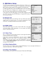
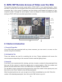
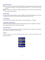
8. DVR-16IP Remote Access of Video over the Web
This section discusses the remote control ability of DVR-16/IP; it is an optional function. Users
are able to access live and recoded video from remote site through Internet with Ethernet port
connected. Key in the correct IP address, and then below control panel will appear on your
computer screen. Through the control panel, users are allowed to control and setup the OSD
settings of DVR-16/IP and connected speed dome remotely.
9
10
1
2
11
3
12
4
5
6
13
7
8
8.1 Button Introduction
1. Zoom In/ Zoom Out
If the DVR-16/IP has connected with any dome cameras, you can zoom in or zoom out the
camera using the two buttons.
2. Iris Near/ Iris Far
These two buttons are used for controlling the iris lens. Proper adjustment will ensure the
correct exposure depending on the camera’s situation and the lighting levels.
3. Preset Pt.
If you want to set a preset point for viewing, you have to enter a number for the preset point first,
then pan/ tilt the camera to select the preset point a wanted position. After the number and
position are both determined, click on the “Set” button to complete the procedure.
You are able to clear a preset point at the same time; enter the number of that preset point, and
then click on the “Clear” button to clear off the preset point.
After the preset points are set, you can go to one of them immediately by one click. Enter the
number of the desired preset point, then click on the “Go” button to go to it.
32
4. Direction buttons
4.1 If the “Pan/ Tilt” (check box) is enabled (default), these buttons are used to pan/ tilt the
connected dome cameras. Choose a wanted camera through “P/ T/ Z ID” before you tried to
pan/ tilt it.
4.2 If the “Pan/ Tilt” (check box) is disabled, these buttons can be used to select OSD menu
items of speed dome camera.
5. Menu/ Enter
In normal status, press this button to enter the OSD menu of connected speed dome camera.
This button is used as “Enter” button while in speed dome OSD menu mode.
6. Step Degree
Users can set the step degree of dome camera. You can choose form 1~15 degree.
7. DVR-16/IP-related buttons
Please refer to page 6 for the descriptions of these button functions. The password is required
before entering the DVR-16/IP menu through Internet.
8. Device Protocol
Here allow you to set the device protocol. For a communication to be successful, each device
must recognize and follow the same standard.
9. Sever
Press this button to go to the sever-related menu (Figure 1). Users can modify the sever
settings in this menu.
<Figure 1>
33
9.1 Server
You can set the server settings in this menu.
9.1.1 General
Users can set the general server settings here in this sub-menu (Figure 2). The MAC
address will be detected and shown on the test box automatically.
<Figure 2>
9.1.2 User
This sub-menu allows you to set the authorized user’s name, individual password and
the permission level (Figure 3).
<Figure 3>
Different user has different default password with respective permission, as below:
User Permission
Administrator
Operator
Guest
ID
owner
operator
guest
34
Password
owner
operator
guest
9.1.3 System
Choose “Save Changes” to save the modifications you’ve made (Figure 4).
<Figure 4>
9.2 Network
This sub-menu is offered to set network settings.
9.2.1 Network settings
You can set the network-related setting here (Figure 5), including IP address, subnet
mask…
<Figure 5>
35
9.2.2 Dynamic DNS Configuration
This sub-menu allows you to set the DDNS settings (Figure 6).
<Figure 6>
9.3 Video
This sub-menu allows you to set the video quality and PPS (Picture Per Second) (Figure7).
<Figure 7>
10. GET ID
Press this button to show the DVR-16/IP ID on the screen.
36
11. Password
Each password contains 4 characters. If you want to enter DVR-16/IP menu or enter
playback mode, you have to enter correct password. You need to key the password in the
field then press “send” button before you enter DVR-16/IP menu or playback mode. The
password shown on screen will not change but you are already able to enter DVR-16/IP main
menu to change settings or to enter playback mode.
12. Channel Buttons
The number of channel buttons corresponds to the number of channels supported by the unit.
Press one of these buttons to view the channel full screen.
Note:
If you want to select DVR-16/IP menu item, you don’t have to do it by directional key. You can
use Channel Buttons instead. For example, if you want to select DVR-16/IP menu item 3
Monitor, you can just press Channel Button “3” on the right side.
13. DVR-16/IP ID
Users can set the DVR-16/IP ID here.
9. Connectors
Rear Board
5
6
1
Item
1
2
3
4
5
7
8
9
10
2
Description
Item
External I/O
6
Main Monitor output (S-Video)
7
Video Looping (1~16)
8
Power Jack
9
IDE Port
10
3
Description
RS-485 Port
Call Monitor Output (BNC)
Main Monitor Output (BNC)
LAN Port
Video Input (1~16)
37
4
External I/O Port (37pin DSUB)
Pin No.
1
2
3
4
5
6
7
8
9
10
11
12
13
14
15
16
17
18
19
Definition
GND
GND
GND
GND
Reserved
Reserved
Alarm NO
Alarm COM
Alarm NC
GND
GND
GND
GND
GND
GND
Alarm In 16
Alarm In 15
Alarm In 14
Alarm In 1
Direction
Power
Power
Power
Power
Output
Output
Output
Power
Power
Power
Power
Power
Power
Input
Input
Input
Input
Pin No.
20
21
22
23
24
25
26
27
28
29
30
31
32
33
34
35
36
37
Definition
Reserved
Reset Alarm
Day / Night output
Day / Night switch
Set Alarm
Reserved
Alarm In 13
Alarm In 12
Alarm In 11
Alarm In 10
Alarm In 9
Alarm In 8
Alarm In 7
Alarm In 6
Alarm In 5
Alarm In 4
Alarm In 3
Alarm In 2
Direction
Input
Input
Output
Input
Input
Input
Input
Input
Input
Input
Input
Input
Input
Input
Input
Input
Input
External I/O Board
There is an “External I/O board” included in the DVR-16/IP box. You can connect it to the
External I/O port; the pins are identified as the definitions listed on the board. Three pins are
listed but of no use: VCR Trigger, RS-232 RX and RS-232 TX.
38
RS-485 (RJ11)
The default RS-485 port connector is RJ11 6P6C connector.
RJ11 Cable 6P6C pin definition:
Pin No.
1
2
3
4
5
6
Definition
GND
DA (D +)
DB (D −)
-
Direction
Reserved
Ground
I/O
I/O
-
10. Specification
Model Name
Compression Method
Video System
Resolution-Live Video
Resolution-Recorded
Recording Rate
Recording Device
Video Export
Recording Quality
Video Input
Video Looping Through
Main Monitor Output
Call Monitor Output
Alarm Input
Alarm Output
Network Interface
Remote Control
Playback Speed
Zoom
Power Supply
Title
Alarm List
Dimensions
Operating Temperature
DVR-16/IP
Wavelet
NTSC
PAL
720 x 480 pixels
720 x 576 pixels
720 x 240 pixels
720 x 288 pixels
Up to 60 PPS
Up to 50 PPS
Hot swappable HDD
CD-RW
Supper / High / Normal / Low
BNC x 16, 1.0 Vp-p, 75 ohm.
BNC x 16, 1.0 Vp-p, 75 ohm.
BNC x 1, S-VHS x 1, 1.0 Vp-p, 75 ohm.
BNC x 1, 1.0 Vp-p, 75 ohm.
x 16, DSUB 37 pin male (TTL level)
x 1, DSUB 37 pin male, 2.0 A / 24 V
Ethernet (10 Base-T) (Optional function)
RS-485 DSCP
Fast Forward / Rewind (x1~x8), picture by picture
Yes
DC 12 V / 4 A
12 characters
Up to 255 events
432 x 44 x 400mm (W x H x D)
0~40°C
39
Appendix 1: Hard Disk Error Message
Some messages will be shown on the screen when the H.D.D. cannot operate.
Message: HDD Detect Time Out
Symptom: The system checks H.D.D. but gets no response over 30 seconds
Possible reason: H.D.D. power on failure
Countermeasure: 1). Wait for the DVR resets the H.D.D. automatically; 2). Power off and on
again
Message: No Hard Disk
Symptom: No HDD has been found by the system.
Possible reason: 1). No H.D.D; 2). H.D.D. detects failure
Countermeasure: 1). Insert a formatted (FAT 32) H.D.D; 2). Check the power/ IDE bus
connectors, ensure they have been connected well; and then insert the
HDD again.
Message: Check HDD Bus
Symptom: IDE bus error or H.D.D. Master/ Slave jumper error.
Possible reason: 1).The cable of IDE connectors may be damaged; 2). H.D.D. jumper may
not be set to “Master”.
Countermeasure: 1). Check the cable of IDE connectors; it may be damaged; 2). Check the
H.D.D. cable; ensure it has been connected with the cartridge well; 3).
Check H.D.D. jumper; the jumper has to be set to “Master”.
Message: Unknown HDD
Symptom: 1). The H.D.D. format is not acceptable.
2). The file system is not acceptable.
Possible reason: 1). The H.D.D. had been formatted with “NTFS” file system; 2). The H.D.D.
had been partitioned or the HDD had not been formatted with “FAT32” file
system.
Countermeasure: Enter OSD menu and format the H.D.D. again.
Message: HDD Detect Fail
Symptom: The HDD is unusable.
Possible reason: Other unknown reasons.
Countermeasure: Exchange the H.D.D. for a new one.
40
Appendix 2: Supported HDD
The supported HDDs are listed as below:
Brand
Capacity
Rotation Speed
Maxtor
40GB
5400 RPM
Maxtor
80GB
5400 RPM
Maxtor
80GB
7200 RPM
Maxtor
80GB
7200RPM
Maxtor
120GB
7200RPM
Maxtor
160GB
7200RPM
Maxtor
200GB
7200RPM
Maxtor
250GB
7200RPM
Part Number
4D040k2
4D080H4
D740X-6L
6Y080P0
6Y120P0
6Y160P0
6Y200P0
7Y250P0
Notice:
1. We strongly suggest do NOT use Seagate products, because them might have overheated
problems while the DVR-16/IP is operating.
2. We had compared other brand HDDs with Maxtor HDDs, we recommend user to use Maxtor
HDDs with 8MB cache buffer that would bring DVR the optimum stability.
41
Appendix 3: RS-485 Command Set
The texts of Data 0, 1 is in ASCII code format (Normal Command)
Command
OP_code Data 0,1
Note
Channel select
“01” ~ ”0G”
Channel 1~16
Right
“MR”
Detail setting must
Screen mode select
reference User’s manual
Left
“ML”
Sequence
“S1” ~ ”S3”
Sequence 1~3
Up key
“DU”
Down key
“DD”
Left key
“DL”
Right key
“DR”
Zoom/Enter
“DZ”
Play key
“KV”
Freeze/Pause
“KA”
A0H
Set
“KS”
ESC
“KE”
List
“KL”
Date/Time
“SD”
Title
“ST”
Menu
“SP”
Key Lock
“SK”
Lock/ Un_Locked
Goto
“SR”
Fast Rewind
“RW”
x1,x2,x4,x8
Fast Forward
“FF”
x1,x2,x4,x8
Universal End
“UE”
Goto Time1
BDH
Data1, Data0
Year & Month
Goto Time2
BEH
Data1, Data0
Day & Hour
Goto Time3
BFH
Data1, Data0
Minute & “G”
PS: Goto Time1: Year=00~99 (it means 2000~2099); Month=01~12
Goto Time2: Day=01~31; Hour=00~23
Goto Time3: Minute=00~59; “G” ASCII=47H
Example:
If the Keyboard ID is 00H, the DVR-16/IP ID is E0H.
If you want to select camera 0 on the main monitor, you can use ‘01’ command.
(The ASCII Code of ‘01’ is 30H & 31H.)
Byte 1
Byte 2
Byte 3
Transmitter
Receiver ID
OP Code
ID
E0H
00H
A0H
NOTE:
Byte 4
Byte 5
Byte 6
Data0
Data1
Checksum
30H
31H
41H
1. The time interval between byte and byte must be shorter than 2ms, and the time interval
between 2 commands (6 bytes/command) must be longer than 2ms.
2. Checksum = Byte1 .xor. Byte2 .xor. Byte3 .xor. Byte4 .xor. Byte5
42
Appendix 4: Super MMX & Super MPX System Setup
1. MMX (Multiplexer-Matrix)
Purpose: by using the call monitor output of the DVR-16/IP/multiplexer array to mimic (or
emulate) a small matrix system, each one of the camera can be selected to be displayed on the
system monitor.
Ex: when users want to view camera 32, in keyboard’s speed dome mode, press camera
number 32, then Enter, the system monitor will show the video from camera 32. If camera 32
happens to be a dome camera, he may use the joystick to control it immediately.
System diagram:
Notice:
(1) All DVR-16/IPs shown in the diagram can be Triplex Multiplexer.
(2) All DVR-16/IPs / multiplexers must enable Super MMX (in OSD menu)
(3) Choose “Super MMX” from “System Monitor Setting” in keyboard’s “System Setting”
(4) All devices must be connected to the same RS485 bus. In security system, the Dome
Cameras are mapping to each channel of the DVR-16/IP / multiplexer. For example, Dome
1 is mapped to channel 1 of S1 (MPX 1). Dome 24 is mapped to channel 8 of S2 (MPX 2)…
and so on. When using keyboard as a system controller, please set up each device’s ID
according to the following table:
(5) The ID of DVR-16/IP / multiplexer P1 is 255.
43
MPX NO
1
2
3
4
5
6
7
8
9
10
11
12
13
14
15
16
MPX ID
E0H, 224
E1H, 225
E2H, 226
E3H, 227
E4H, 228
E5H, 229
E6H, 230
E7H, 231
E8H, 232
E9H, 233
EAH, 234
EBH, 235
ECH, 236
EDH, 237
EEH, 238
EFH, 239
Camera ID
01H – 10H, 1~16
11H – 20H, 17~32
21H – 30H, 33~48
31H – 40H, 49~64
41H – 50H, 65~80
51H – 60H, 81~96
61H – 70H, 97~112
71H – 80H, 113~128
81H – 90H, 129~144
91H – A0H, 145~160
A1H – B0H, 161~176
B1H – C0H, 177~192
C1H – D0H, 193~208
D0H – DFH, 209~223
None
None
Remark
Channel 1~16 of MPX #1
Only 15 Dome can be connect
Can connect to normal camera
Can connect to normal camera
2. Super MPX (Super Multiplexer Mode)
Purpose: use Main Monitor instead of Call Monitor, the feature of selecting particular camera to
the system monitor is the same as MMX mode. Besides of this, by setting the multiplexers
correctly, all of the cameras in this system can be displayed on the system monitor sequentially.
Ex: set the P1 multiplexer to Full Screen Sequence mode, dwell time = 3 seconds. Set S1 to
S16 multiplexer to 4x4 display mode. Then in 48 seconds, all 256 cameras will be displayed on
the system monitor sequentially.
System Diagram:
44
Notice:
(1) All Multiplexers shown in the diagram can be DVR-16/IPs.
(2) Choose “Super MPX” from “System Monitor Setting” in keyboard’s “System Setting”
(3) All the device must be connected to the same RS485 bus, the RS485 ID for each device
must be set up as indicated in the above table.
45