1
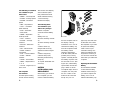
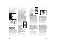
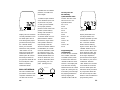
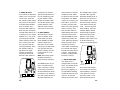
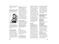
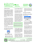
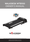
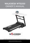
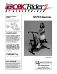
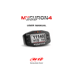
2004 TURBO® PRO
CYCLOCOMPUTER
Congratulations on your purchase! You are now the
owner of the world’s most advanced cyclocomputer.
Your Specialized Turbo® Pro features a wireless speed
transmitter and a wired cadence sensor. Additionally, it
incorporates a revolutionary new backlit three-line LCD
screen. The large, easy to read, digits allow you to view
two functions simultaneously and the alphanumeric dot
matrix display provides a quick reference to the currently
displayed function. The Turbo® Pro has been designed
to provide the best combination of performance,
features, durability and ease of use.
3
7
4
5
6
8
2
1
FIGURE 1
This illustration describes the screen display and buttons
1- MODE rocker switch
2- SET rocker switch
3- TOP Button (Backlight & Start/stop)
4- Digital Display Area
5- Secondary Function Display Area
6- Dot-matrix Display Area
7- MPH or KM/H indicator
8- Wheel Option Indicator
1
The following 17 functions
are available on your
Turbo® Pro:
• SPEED – Current Speed
• AVSPD – Average speed
• MXSPD – Maximum
Speed
• TRIP – Trip Distance
• ODO – Odometer
(total distance)
• ATM – Automatic
• Start/Timer
• TIMER – Stopwatch
With Lap-timer
• CAD – Cadence
• AVCAD – Average
Cadence
• MXCAD – Maximum
Cadence
• INT – Interval Timer
• DISTÚ– Distance
Countdown
• ALTI – Current Altitude
• ALTIÒ – Altitude
Climbed
• %GRD – Inclinometer
• TEMP – Temperature in
˚C or ˚F
• CLOCK – Digital 12/24
Hour Clock
This computer
also features:
Wireless speed sensing
Wired cadence sensing
2
Two function LCD Display
Second Wheel Option
Easy Calibration Mode
Water resistant housing
2 Year Warranty
Backlit LCD display
The following items
are included in your
Turbo® Pro package:
Turbo® Computer
CR-2032 Lithium Battery
(1)
Battery Door (1)
26.0mm mounting bracket
(1)
31.8mm mounting bracket
(1)
Cadence sensor (1)
Magnet with screw (1)
Adhesive backed magnet
(1)
Cadence magnet (1)
Cable tie wraps (10)
Mounting bracket sizing
straps (3)
11. Speed Transmitter and
mount (1)
BATTERY
INSTALLATION AND
REPLACEMENT
Before using your Turbo®
Pro Computer you will
need to install the battery.
FIGURE 2
Turn the computer over so
the display is facing
downward. Use a coin to
unthread the battery cap
from the computer. Install
the battery (model
CR2032, Specialized
P/N 481-3004) with the
positive pole (+) facing
upward. Carefully thread
the battery cap back onto
the case with a coin. (See
Figure 3) If, after battery
replacement, the LCD display is blank or shows
incomplete digits, turn the
computer over and press
the “AC” button on the
bottom of the case with
the tip of a pen or a
paper clip. This will clear
all the data and re-start
the computer. If you need
to replace the battery,
make a note of your
odometer reading and
wheel circumference settings before removing it.
You can then re-enter the
data when you restart the
computer.
Replacing the Transmitter
Battery
The Wireless Transmitter
comes with the battery
installed at the factory. If
you need to replace this
battery, use a coin to
unthread the battery cap
3
from the transmitter housing. Install the battery
(model 23A) with the positive pole (+) facing
upward. Carefully thread
the battery cap back onto
the case with a coin.
FIGURE 3: BATTERY
INSTALLATION
4 screws
CR2032 battery
Rubber O-ring
23A battery
the transmitter is 24 inches
(610mm). The distance
may need to be less than
24 inches (610mm) if
ambient temperatures are
below 40 °F (4 °C). To
reduce signal loss in colder
temperatures, the transmitter should be mounted as
close to the computer as
possible. (Maximum
mounting distance is 28
inches). Use the transmitter-mounting shim and tiewraps provided to position
the sensor. Do not tighten
the tie-wraps until final
placement of
the magnet is
correct. (See
figure 4).
Wheel magnets
have been provided for both
traditional
FIGURE 4
round spokes
and bladed (flat) aerodynamic spokes.
For wheels with round
spokes:
Attach the magnet to a
spoke across from the
transmitter with the magnet
screw. The clearance
between the magnet and
20-28 in.
500-700mm
Tightening
sequence
FIGURE 3
MOUNTING THE
TURBO® PRO:
The Turbo® Pro wireless
transmitter can mount on
the right or the left side of
the fork blade. The right
side should be used on
large frames or when a
suspension fork is installed.
The optimal distance
between the computer and
4
the transmitter should be
approximately 1/32”1/16” (12mm). Tighten
the magnet and
transmitter. Do
not over-tighten
the magnet
screw.
(See figure 5). FIGURE 5
For wheels
with bladed spokes:
Use some isopropyl (rubbing) alcohol or a mild
detergent to thoroughly
clean the spoke that you
plan to attach the magnet
to. Remove the backing
from the adhesive tape and
firmly press the magnet
onto spoke. The tape uses
a special pressure sensitive
adhesive. To ensure a
strong bond, please wait at
least 12 hours for the
adhesive to cure before riding your bicycle.
dlebar. There are several
sizing straps provided to fit
different diameter bars.
(See figure 6). Slide the
computer rearward onto
1/32-1/16 in.
1-2mm
Attach the appropriate
mount (26.0mm and
31.8mm sizes are included) to the handlebar using
the bracket screw provided.
Tighten so that the bracket
cannot rotate on the han-
FIGURE 6
the mount until it ‘snaps’
into place with an audible
click. To remove the computer, remove the cadence
wire (if connected) then
push it forward until it
releases from the mount.
To test for proper installation of the magnet, transmitter and computer, activate the computer by pushing the ‘MODE’ (right side)
button. Pick up the front of
the bicycle and spin the
front wheel. The “wheel
option” indicator will flash.
If it does not flash, check
the sensor and magnet
alignment. Realign as necessary until the “wheel
option” indicator flashes
while spinning the wheel
5
FIGURES 7, 8 & 9
FIGURE 7, 8 & 9
Mounting Cadence hardware- In order to use the
cadence option you must
install the cadence wire
provided with your Turbo®
Pro. Plug the wire into the
socket on the bottom of
your computer. Run the
cadence sensor wire along
the head tube, down tube
and along one of the chain
stays of your bicycle.
Secure it into place using
the provided tie-wraps.
(See figure 7). Next, attach
the cadence magnet to the
6
inside of your crank arm
directly across from the
sensor. Use a tie-wrap to
fasten the magnet to the
crank arm. (See figure 8).
Do not tighten the tie-wrap
until final placement of the
magnet is correct. The
clearance between the
magnet and the sensor
should be approximately
1/32”-1/16” (1-2mm).
(See figure 9). Tighten the
magnet and sensor.
OPERATION AND
PROGRAMMING
When your Turbo® Pro has
not detected any speed input
for 30 minutes, it will enter
sleep-mode in order to conserve battery power. During
sleep mode only the digital
clock is displayed. You will
need to wake it up by pushing the “Mode” or “Set” button once. In order to operate
your computer it must be
placed in various “modes”
(i.e. odometer mode, distance mode). The computer
can be cycled through these
modes by pressing the
“MODE” button located on
the right-hand side the
MODE/SET rocker switch.
There are eight cycling
modes available: 1) Clock
Mode, 2) Distance Mode, 3)
Speed Mode, 4) Timer
Mode, 5) Cadence Mode, 6)
Countdown Mode, 7)
Altitude Mode and 8)
Temperature Mode. Within
each mode there is a sidemode that will allow you to
access additional information such as average and
maximum speeds. Use the
“SET” button, located on the
left-hand side the
MODE/SET rocker switch, to
cycle through the sidemodes. Once you familiarize
yourself with the mode/sidemode operation you will find
it very easy to navigate. The
following flowchart outlines
the mode/side-mode
sequence. Once a particular
mode has been entered, its
values can be reset or
adjusted by pressing and
holding the “SET ” button for
three seconds.
1. Setting the
Display Language
Your Turbo® ® Pro can
display information on the
CLOCK
I
TRIP – ODO
I
AVSPD – MXSPD
I
ATM – TIMER
I
CAD – AVCAD – MXCAD
I
INT – Dist
I
–%GRD
ALTI – ALTI
I
TEMP ˚F – TEMP ˚C
dot-matrix display area in
six different languages:
English (ENGL), German
(GER), French (FR), Italian
(ITA), Dutch (NED), and
Spanish (ESP). To select
your language push the
mode button repeatedly
until CLOCK is displayed
in the Dot-matrix Display
Area. Then, depress hold
the “MODE” button for
three seconds. The selected
language will be displayed. Use the “MODE”
button to scroll through the
languages. When the
selected language is displayed (default language is
English), press the “SET”
button once to confirm
your selection and exit display language mode.
7
2. Miles or Kilometers
selection (English only):
Your Turbo® Pro will
record distance and speed
in either miles (m & m/h)
or kilometers (K & Km/h).
Please note that miles can
only be selected when the
language setting is English.
All other languages display only kilometers. (See
“Setting the Display
Language” above). To
enter your selection of
miles or kilometers, push
the “MODE” button until
ODO appears in the Dotmatrix Display Area (This
is called the odometer
mode). Note: if your display says TRIP, press the
“SET” button once to
change to ODO. Next,
hold down the “SET” button for three seconds. The
“Km” or “m” indicator will
begin blinking. You may
now alternate between
miles and kilometers by
pressing the “MODE” button. When the correct
choice is flashing, select it
by pressing the “SET” button. You will now enter the
8
“Programmable
Odometer” mode. If the
odometer setting is correct
push the “SET” button five
times to exit odometer
mode. (Otherwise, see
“Setting the programmable
odometer” below).
3. Setting the
Programmable Odometer:
This mode is useful if you
have replaced the battery
and would like to retain
the mileage you have
already ridden. To access
the Programmable odometer mode, first advance to
the Odometer Mode by
pressing “MODE” button
until ODO appears in the
Dot-matrix Display Area.
Note: if your display says
TRIP, press the “SET” button
once to change to ODO.
Hold down the “SET” button for three seconds (If
you have selected English
language, the Km/h indicator will flash. If the Km/h
setting is correct press the
“SET” button once) and a
five-digit number will
appear. You are now in the
programmable odometer
mode. To enter a mileage
into the odometer, press the
“MODE” button until the
flashing digit is correct.
(Note: The “MODE” button
may be held to quickly
scroll to the correct digit.)
Press the “SET” button to
select the next digit to the
right. Repeat this process
until all five digits are
entered as your existing
mileage. (See figure 10)
FIGURE 10
4. Wheel Circumference
Selection:
To set the circumference for
the type of tires you are
using, you can use
Specialized’s “Easy
Calibration Mode” or
measure your actual tire
circumference by the rollout
method. Two different tire
diameters may be entered
by using the computer’s
“Second Wheel Option.”
Easy Calibration Mode:
Your Turbo® Pro has been
preprogrammed with the
following 14 Specialized
tire sizes:
26 X 1.0
26 X 2.2
26 X 1.25
650c X 20
26 X 1.5
700c X 20
26 X 1.9
700c X 23
26 X 1.95
700c X 26
26 X 2.0
700c X 32
26 X 2.1
700c X 38
When using Easy
Calibration Mode, the
Turbo® Pro will display
the tire size on its LCD display screen. (See figure
11) The Easy Calibration
Mode is accessed by
entering the Odometer
(ODO) mode and holding
down the “MODE” button
for three seconds. The
9
variables such as inflation
pressure, rim width and
rider weight.
FIGURE 11
display will now show the
currently selected tire size
for wheel option #1. To
scroll through the preprogrammed tire sizes press
the “MODE” button.
When you reach the
desired tire size press the
“SET” button once to
select it and enter Easy
Calibration Mode for
wheel option #2. Follow
the same procedure to
program the wheel #2 tire
size and tap the “SET”
button to exit Easy
Calibration Mode.
1. Extend a tape measure
out to 3000mm (120 inches) and lock it in place.
2. With your tire inflated
to its proper pressure,
place the valve at the 6:00
position (at the bottom)
directly over the start of
the measuring tape.
3. Roll the wheel one complete revolution until the
valve stem is again at the
6:00 position. Read the
tape directly under the
valve and note the distance
in millimeters. (To convert
inches to millimeters, multiply inches by 25.4). Use
this number to replace the
default (default values are
2073 for wheel one, and
2134 for wheel two) when
programming your computer. (See figure 12).
Roll Forward
ROLL OUT METHOD
The roll out method will
provide the most accurate
computer calibration and
can take into account
10
stem
Wheel Circumfrence
FIGURE 12
You may also use
the following
quick-reference chart:
Generic Tire Size Chart
This chart is for nonSpecialized tires
26 X 1.75
2140
26 X 2.0
2074
26 X 2.1
2090
650C X 20
1945
700C X 26
2124
700C X 38
2170
Programming the
circumference:
To enter the tire circumference number, select the
Odometer (ODO) mode
and then hold down the
“MODE” button for three
seconds. The display will
now show the currently
selected tire size for wheel
option #1. (See figure 13).
If necessary scroll through
the preprogrammed tire
sizes by tapping the
“MODE” button until the
FIGURE 13
display shows MM and
four-digit number. This
number represents your tire
circumference in millimeters. Press the “MODE”
button until the flashing
digit is correct. (Note: The
“MODE” button may be
held to scroll to the correct
digit.) Press the “SET” button to select the next digit
to the right. Repeat the
process until all four digits
are entered as your tire circumference. Press the
“SET” button once to select
it and enter the circumference for wheel option #2.
Follow the same procedure
to program the wheel #2
tire size and tap the “SET”
button to exit circumference
programming mode.
11
5. Setting the Clock
Your Turbo® Pro features a
digital clock. To access the
“clock mode” press and
the “MODE” button repeatedly until CLOCK appears
in the Dot-matrix Display
Area. To set the clock,
press the “SET” button for
three seconds. The display
will flash either twelve (12:)
or twenty four (24:). Select
between 12: or 24: mode
by pressing the “MODE”
button. Press the “SET” button to confirm your selection. The hour digit will
now begin flashing. Press
the “MODE” button to
adjust the hour digits.
AM/PM is selected by
scrolling the hour digit.
Press the “SET” button to
FIGURE 14
12
accept the hour selection.
The minutes will flash and
can be adjusted by pressing the “MODE” button.
(Hold the “MODE” button
to scroll through the digits
quickly) Press the “SET”
button to set the minutes
and return to clock mode
6. Timer Selection
The Turbo® Pro has two
timers; Automatic Timer
Mode (ATM) and Timer
Mode (TIMER). The ATM
selection allows you to
keep track of your actual
riding time. The ATM timer
only operates when the
wheel is rotating and cannot be turned on or off
manually.
Note: The average speed
(AVSPD) calculation is
based upon the ATM time.
The TIMER function is just
like a conventional stopwatch. The timer is activated manually and records
the time whether the wheel
is rotating or not. Tapping
the “TOP” button starts and
stops the stopwatch and
when the timer is stopped,
holding the “SET” button
for three seconds will reset
to stopwatch. The TIMER
includes a 12-memory lap
time feature. To record a
lap time, press the “SET”
button once while the stopwatch is running. Each
time the “SET” button is
depressed the Turbo® Pro
will record the lap time.
After the TIMER has been
stopped (by pressing the
“TOP” button) the previous
twelve lap times can be
reviewed by pressing
“SET” button. Additionally,
the computer will display
the total time when LPTOT
is shown. The backlight
function is disabled when
the timer is running.
7. Interval Timer (INT)
Your Turbo® Pro is
equipped with an Interval
Timer. This feature allows
you to customize your
training by integrating a
programmable repeating
countdown timer into your
workout. To enter the
interval timer mode, press
the “MODE button” repeatedly until “INT” appears
Dot Matrix Display Area of
the screen. You are now in
interval timer mode. To set
the interval timer, hold the
“SET” button for three seconds. The hour digit will
begin flashing. Press the
“MODE” Button until the
desired number appears.
(Hold down the “Mode”
button to scroll quickly)
Press the “SET” button once
to set this number and
advance to minutes. Repeat
FIGURE 15
this process until minutes
and seconds are set to the
desired settings. Press the
“SET” button to exit programming mode. Once
the time interval timer is
13
programmed, press the
“TOP” button to start/stop
the countdown. (See figure 15). Note: The shortest
interval that can be set is 5
seconds. The backlight
function is disabled when
the interval timer is running.
8. Altimeter (ALTI)
Your Turbo® Pro contains
an extremely accurate
altimeter that is capable of
recording changes in altitude in increments as small
as three feet (one meter).
This altimeter calculates
altitude by precisely measuring barometric pressure.
Due to normal changes in
barometric pressure, you
may need to recalibrate
your Turbo® Pro on a
daily basis. You should be
able to find the altitude
where you live on a topographical map or by contacting a nearby airport.
Altimeter Calibration
To calibrate your altimeter,
press the “MODE” button
14
until “ALTI” appears. Note:
if your display says
“ALTIÒ” or “%GRD”, press
the “SET” button to change
to “ALTI”. Then press the
“SET” button for three seconds. The first altitude digit
will begin flashing. Press
the “MODE” button until
the desired number
appears. Press the “SET”
button once to set this number and advance to the
next. Repeat this process
until you have entered the
desired altitude. Press the
“SET” button to exit programming mode.
Note: Altitude will be displayed in feet when speed
is measured in miles per
hour and in meters when
speed is measure in kilometers per hour.
9. Altitude Climbed
The Altitude Climbed function on your Turbo® Pro
calculates the total altitude
gained during your ride.
Descended altitude is not
counted. To reset the
Altitude Climbed to zero,
press and hold the “SET”
button for three seconds.
10. Distance Countdown
(DISTÚ)
Your Turbo® Pro is
equipped with Distance
Countdown feature. This
allows you to set an alarm
when the selected mileage
is reached. To enter the
Distance Countdown mode,
press the “MODE” button
repeatedly until “DISTÚ”
appears in the Dot-matrix
Display Area. Note: if your
display says “INT, press the
“SET” button to change to
“DISTÚ” To set the Distance
Countdown, hold the “SET”
button for three seconds.
The hour digit will begin
flashing. Press the
“MODE” Button until the
desired number appears.
(Hold down the “Mode”
button to scroll quickly)
Press the “SET” button once
to set this number and
advance to minutes. Repeat
this process until minutes
and seconds are set to the
desired settings. Press the
“SET” button to exit pro-
gramming mode. Once
the time interval timer is
programmed, press the
“TOP” button to stop and
start the Distance
Countdown. The backlight
function is disabled when
the Distance Countdown is
running.
Note: The shortest distance
that can be set is .01
miles/km.
COMPUTER
FUNCTIONS
Speedometer (SPEED)Your current speed is always
displayed in large digits on
the top line of the LCD
screen. The speed is displayed up to 99.9 M/h
(99.9 Km/h) with a resolution of 0.1 M/h (0.1 Km/h)
Average Speed (AVSPD)The Average Speed is
shown on the lower line
Digital Display Area up to
99.9 M/h (99.9 Km/h)
with a resolution of 0.1
M/h (0.1 Km/h)
The average speed is
based upon the ATM time.
15
the screen when (INT)
appears on the left. The
timer indicates the end of
an interval with one short
beep per second for the last
4 seconds of the interval.
This is followed by a long
beep, indicating the beginning of a new interval.
The resolution of the average speed data on the
Digital Display Area is
shown in 0.1M/h or Km/h
increments. (See figure 16)
FIGURE 17
FIGURE 16
Maximum Speed (MXSPD)The Maximum Speed is
shown on the lower line of
the Digital Display Area up
to 99.9 M/h (99.9 Km/h)
with a resolution of 0.1 M/h
(0.1 Km/h) The maximum
speed is retained in memory
and updated when a higher
speed is maintained for three
seconds. The maximum
speed can be reset by pressing the “SET” button for three
seconds. (See figure 17)
16
Auto Start/Stop Timer
(ATM)In ATM mode the timer
function records the actual
time spent riding. It operates only when there is
speed input and is displayed In the Digital
Display Area of the screen
Timer Mode (TIMER)In TIMER mode the stopwatch function will operate
when the “TOP” button is
pressed. The stopwatch will
record the total time after
the button is pressed
regardless of whether there
is speed input or not.
Interval Timer (INT)The interval timer is displayed on the lower line of
Cadence (CAD)Cadence mode will display
your pedaling speed in
RPM’s (revolutions per
minute) on the lower line
of the screen. Monitoring
how fast you turn your
pedals can be used as a
tool to enhance the efficiency with which you ride
your bicycle. Simply put,
the best cadence is a balance between leg speed
and pedal pressure.
Beginning cyclists typically
prefer to pedal at a slower
cadence, around 60-rpm,
while advanced cyclists
and racers are more efficient between 90 and 100
rpm. Your Turbo® Pro can
also display Average and
Maximum Cadence.
Trip Distance (DST)Trip distance mode will
FIGURE 18
record up to 999.99 miles
or kilometers and then roll
to zero. The trip distance
can be reset by pressing
the “SET” button for three
seconds. The resolution is
0.01 miles (0.01
Kilometers). The trip distance is shown on the
lower line if the screen.
(See figure19)
Odometer (ODO)The odometer will record
the total distance traveled
up to 99,999 miles or kilometers and then roll to
zero. The odometer can be
reset by pressing the “SET”
button for three seconds.
17
The total distance is shown
on the lower line if the
screen.
Tech note: The inclinometer
calculates percentage of
grade by comparing the
Programmable Odometer- change in altitude to the
The odometer digits are
distance traveled. This data
programmable. This is con- is updated on the LCD display every 5 seconds and
is based upon data accumulated during the previous 20 seconds. It is normal to experience a slight
delay when transitioning
from one grade to another.
FIGURE 19
venient for transferring
your hard-earned mileage
that is usually lost when
changing batteries or computers.
Inclinometer (%GRD)
The inclinometer will display the percentage of
grade you are climbing or
descending in increments
of 1%. A negative grade
or descent is indicated by
a negative sign (example
–3%).
18
Temperature (TEMP)
Your Turbo® Pro is contains
a thermometer. Temperature
is displayed in increments
of one degree. While in
“TEMP” mode, press the
“SET” button to alternate
between ˚C and ˚F.
ClockYour Turbo® Pro is
equipped with a digital
clock. The clock can be set
to operate in either 12 or
24-hour mode.
Second Wheel OptionFor riders who own more
than one bicycle or who
frequently change tires, the
Turbo® Pro is capable of
storing two tire sizes. You
can change between the
two sizes by entering
Distance Mode and selecting TRIP. Then, press the
“MODE” button for three
seconds. The second wheel
mode indicator will change
from 1 to 2. Mileage
recorded will be cumulative between the two sizes.
(An accessory handlebar
mount is available from
your Specialized dealer.
4814-5045)
BacklightThe backlight feature of
your Turbo® Elite is activated by pressing the
“TOP” button. The backlight will remain on for 5
seconds after the top button is released. If you
press any button while the
backlight is on, the backlight will remain on for 5
seconds after the last button is released. During the
time the backlight is on,
the current-speed display
will be frozen. Although
the display is not updated,
the Turbo® Elite will continue to monitor time and
distance functions. If the
computer is in sleep-mode,
you can still activate the
backlight without wakingup the computer.
TROUBLESHOOTING:
Display is blank:
Change the battery or
press the AC button on the
bottom of the case
Display shows
partial digits:
Press the AC button on the
bottom of the case.
Speed/distance
not recording:
Check sensor/magnet
alignment. Make sure that
the sensor is no more than
1/16” (2mm) from the
magnet. Replace transmitter battery if necessary.
Recalibrate Computer and
transmitter.
Entire screen is dark:
Did you leave the bike
parked in the hot direct sun
when it was parked? If so,
move the bike to the shade.
The data will be OK.
19
Computer moves
on handlebar:
Tighten mount or add sizing straps to improve fit on
handlebar.
IMPORTANT!
• Pay attention to traffic
and road conditions at all
times. Your first obligation
is to be attentive and to
ride safely.
• Do not expose it to direct
sunlight except when you
are riding.
• Do not disassemble you
Turbo®. There are no user
serviceable parts inside.
• Make sure the magnet
and the transmitter are
well aligned. Check them
regularly.
• Keep the computer and
all of its components tightly
attached, and check them
regularly. If any of the
components come loose, it
could become tangled in
your spokes and cause an
accident.
• See your authorized
Specialized dealer if you
have any trouble installing or
maintaining your computer.
20
• Clean the unit with a
mild detergent and a soft
dry cloth. Never use any
kind of solvent or alcohol.
• The Turbo® Pro computer
is intended for use on bicycles only and should not be
used on any motorized
vehicle.
SPECIFICATIONS:
Current Speed:
0.0 to 99.90 MPH
0.0 to 99.90 Km/H
Average Speed (AVS)
0.0 to 199.9 MPH
0.0 to 199.9 Km/H
Maximum Speed (MXS)
0.0 to 199.9 MPH
to 199.9 Km/H
Trip Distance (DST)
0 to 999.99 miles or Km
Odometer (ODO)
0 to 99,999 miles or Km
Stopwatch (TM)
0 to 9hrs, 59min, 59sec.
recycling type
Automatic Timer (ATM)
0 to 9hrs, 59min, 59sec.
recycling type
Interval Timer (INT)
5 seconds to 9hrs, 59
min, 59 sec.
Distance
Countdown(DISTÚ)
.01 to 999.99Miles
.01 to 999.99Kilometers
Operating Temperature
40°F to 104°F (4°C to
40°C)
The following replacement
parts are available from
your Specialized dealer or
by visiting the Specialized
S-store online at
WWW.SPECIALIZED.COM
DESCRIPTION PART#
STANDARD WHEEL
MAGNET
480-3003
CR-2032 TURBO®
BATTERY
480-3004
ADHESIVE BACKED
WHEEL MAGNET
4800-3002
CENTER MOUNT
4814-5035
TURBO ELITE/PRO 2ND
BIKE KIT
4814-5040
TURBO SPORT/COMP
2ND BIKE KIT 4814-5045
TURBO ELITE/PRO
CADENCE WIRE
4814-5050
TURBO SPORT/COMP
SENSOR WIRE
4814-5055
TURBO MOUNT ONLY
26.0MM
4814-5060
TURBO MOUNT ONLY
31.8MM
4814-5065
Two Year Limited Warranty:
Specialized Bicycle Components
Inc. warrants the Original
Purchaser of this Specialized®
Turbo® Pro cyclocomputer that the
product is free from defects of
material and workmanship under
normal use and service for a period of two (2) years from the date
of the original purchase. If within
two (2) year from the date of that
original purchase, this product is
found to be defective in material or
workmanship under normal use or
service,
Specialized
Bicycle
Components Inc. will, at its sole
option, repair or replace the product without charge; provided that
the Original Purchaser returns the
product, securely packaged,
postage prepaid to: Specialized
Bicycle Components Inc.,
1137 South, 3800 West Salt Lake
21
City, UT 84104, USA. Attn:
Turbo® Pro Warranty. Be sure to
include a letter indicating the specific reasons for returning the
product and proof of date of purchase.
This warranty does not apply to,
and is void as to, defects or physical damage resulting from abuse,
neglect, improper repair, improper fit, alterations, modifications or
use contrary to that intended by
the manufacturer. Except to the
extent prohibited by applicable
law, any implied warranty of merchantability or fitness for a particular use or purpose is limited in
duration of this limited warranty.
Specialized Bicycle Sportonents,
Inc. shall not be liable for any
accidental or consequential damages arising from any breach of
any expressed or implied warranty on this product. This warranty is
exclusive and in lieu of all other
warranties, expressed or implied,
and all other remedies, guaranties
or liabilities arising by law or otherwise.
Note: This warranty does not
pertain to batteries.
No person or representative is
authorized to assume any liability
on behalf of Specialized Bicycle
Components, Inc. in connection with
the sale of this product. Some states
do not allow the exclusion or limitation of incidental or consequential
damages or limitations on how long
an implied warranty lasts, so the
above limitation or exclusion may
not apply to you. This warranty
gives you specific legal rights, and
you may also have other rights
which vary from state to state.
22
Turbo®
is a registered trademark of Specialized Bicycle
Components Inc.
© 2003 Specialized Bicycle
Components Inc.
WWW.SPECIALIZED.COM