1
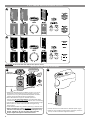
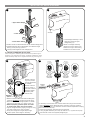
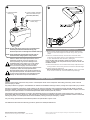
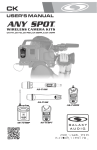
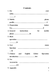
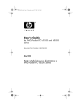
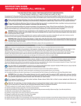
S-WORKS RUBYMAC WEDGE INSTALLATION GUIDE
THIS BRIEF INSTALLATION GUIDE CONTAINS IMPORTANT INFORMATION.
PLEASE READ CAREFULLY AND STORE IN A SAFE PLACE.
Congratulations! The Specialized S-Works Rubymac handlebar/stem system you have chosen is among the finest of advanced composite
products available in cycling. Carbon fiber is a very special material that requires particular care during assembly, storage and riding.
This installation guide contains instructions and warnings, plus torque specifications, to be used in conjunction with the owner’s
manuals and instruction guides supplied with your bicycle.
Please read the following instructions. If you have any doubt regarding your mechanical ability and/or installation of this product, visit your
local authorized dealer. Specialized recommends that the handlebar/stem be installed using a torque wrench, by a qualified mechanic.
Please read the following Warnings. Because the failure to follow any Warning may result in a catastrophic failure of the handlebar,
resulting in serious personal injury or death, this phrase may not be repeated in connection with each Warning.
Bicycle assembly is a complicated task which requires training and experience. Do not attempt installation of any component if you do not
have experience and training as a bicycle mechanic. Reference should also be made to Barnett’s or some other comprehensive bicycle manual.
INTERFACE BETWEEN THE STEM AND THE STEERER TUBE
The S-Works Rubymac Wedge requires that the fork’s steerer tube follows a tolerance range of 28.50mm to 28.65mm. If the steerer
tube tolerances are outside of this range, the fork is not compatible with the Rubymac Wedge.
Proper fit between the steerer tube and the stem is crucial to performance and safety. Incorrect sizing interface can result in
handlebar slippage or failure.
PREPARING THE STEM AND FORK
Before installing the handlebar/stem, ensure that the clamping interface surfaces between the stem and the fork are clean of any grease.
Apply grease to bolt threads and wedge contact surfaces only (see fig.4 & 6).
Do not apply grease to carbon surfaces! Applying grease reduces the friction that is critical to proper stem/handlebar grip.
NOTE: Do not cut fork steerer tube until final stem height is determined, after following assembly steps (fig.4-8).
Once stem height is determined, install the Specialized steerer tube expander plug (supplied with the handlebar) into the top of the
steerer tube. Only use the Specialized 48mm Long Expander Plug, it is designed specifically to maximize internal support for the
Rubymac wedge system when torqued. Do not torque expander plug above fork manufacturer’s recommended torque spec.
CHOOSING THE RIGHT STEM ANGLE
The S-Works Rubymac Wedge handlebar/stem system uses a shim and wedge assembly, which allows for multiple stem angle options.
The nominal position of the stem is +3°. There are 5 angle options available, using a system of shims, wedges and spacers. Determine
the desired stem angle, then assemble the required wedge hardware parts to achieve the correct angle (0° parts pre-assembled in bag):
COMMON PARTS
1 x Upper Outer Wedge
1 x Lower Outer Wedge
1 x Wedge Bolt
1 x Alloy Preload Bolt
1 x Top Cap Rubber Plug
1 x Alloy Steerer Tube Plug
0° PARTS
1 x 0° Inner Wedge (Silver)
1 x 0° Shim (Silver)
1 x 0° Spacer
1 x 0° Centered Top Cap Washer
2° PARTS
1 x 2° Inner Wedge (Coffee)
1 x 2° Shim (Coffee)
1 x 2° Spacer
1 x 2-4° Angled Top Cap Washer
4° PARTS (Black)
1 x 4° Inner Wedge (Black)
1 x 4° Shim (Black)
1 x 4° Spacer
1 x 2-4° Angled Top Cap Washer
0° SETUP (Fig.1):
+3° stem angle
2° SETUP (Fig.2):
(+) setting: +5° stem angle
(-) setting: +1° stem angle
4° SETUP (Fig.3):
(+) setting: +7° stem angle
(-) setting: -1° stem angle
Do not use different angle parts together. Mismatched hardware can result in unevenly distributed loads on the stem and heaset parts, which can lead to failure, causing serious injury or death.
0° WEDGE HARDWARE OPTIONS
2° & 4° ANGLED WEDGE HARDWARE OPTIONS
WARNING! Ensure that the shim tab fits the spacer notch!
INSTALLING THE WEDGE HARDWARE
Recommended Torque:
100 in-lbf (11.3 N-m)
4
GREASE
Aluminum
Contact
Surfaces
48mm
Rubymac
Stem Spacer
5
GREASE
GREASE
GREASE
GREASE
Bike Center Line
t of B
Fron
ike
• Determine desired axle-to-handlebar height. This can be
achieved by either duplicating the position of existing
equipment or using the Specialized Adjustable Fit Stem,
used by select Specialized Authorized Dealers.
• Place desired stack height of headset spacers on
steerer tube (do not exceed 40mm). A Specialized Head
Tube Extender can be used to raise 40mm more if necessary.
• Choose stem spacer that corresponds to desired stem angle.
• Place spacer on steerer tube with desired angle facing
back of stem.
• Install SPECIALIZED Long Steerer Tube Plug in steerer tube.
• NOTE: The Rubymac requires 38-40mm of exposed steerer
tube above the Rubymac stem spacer (including the Long
Steerer Tube Plug). Do not cut steerer tube until after
proper height and angle have been determined.
Shim lip
• Choose the shim that matches the desired spacer (fig.4).
• Place the shim inside the stem against the back (hook the
shim lip under the bottom edge of the stem).
INSTALLING THE WEDGE HARDWARE
6
7
SE
EA
GR
1. Upper Outer Wedge
ASE
GRE
GREASE
Shim lip
2. Inner Wedge
ASE
GREA
SE
GRE
• Install wedge assembly in stem,
Allen Key head and upper
wedge facing up.
3. Lower Outer Wedge
NOTE: The wedge assembly
needs to be held in place from
below with fingers while being
installed on the steerer tube.
• Grease contact surfaces between #1, #2 and #3 wedge parts.
• Place #2 between #1 and #3 wedges, with desired angle
etching on #2 pointing upward.
• Loosely thread together three wedge parts.
0° WEDGE HARDWARE SETUP NOTE:
With no angles or matching tabs and notches, positioning orientation is not important for the 0° hardware. Follow the same
basic assembly steps as for angled hardware (fig.4 through 5).
8
9
Point to
(-) symbol
Point to
(+) symbol
GREASE
-
Steerer tube too
high can prevent
proper adjustment
of headset.
1
38-40mm
2
Steerer tube too
low can result in
too little interface
between wedge
assembly and
steerer tube.
+
2°-4° Top Cap
Washer
2°-4° Top Cap
Washer
0° Top Cap
Washer
Use with
-2° or -4°
Shim, wedge
and spacer
Use with
+2° or +4°
Shim, wedge
and spacer
Use with
0° Shim, wedge
and spacer
Inside top
of stem
Top of steerer
(including plug)
Rubymac
Spacer
• Make sure steerer tube extends above Rubymac
spacer by 38-40mm (including expander plug).
• Place stem, shim and wedge system on steerer
tube, then fit shim tab (1) in spacer notch (2).
• NOTE: Improperly position spacer can result
in uneven loads, which can result in failure.
• Tighten wedge assembly lightly, enough to snug
the stem and align the parts correctly.
• Verify stem height and angle, adjust angle
and/or spacer stack height if necessary.
• If necessary to cut steerer tube, remove steerer tube plug and cut steerer
tube to 38-40mm above Rubymac Spacer (see fork instruction guide for
additional cutting info). This will leave room for headset adjustment and plug.
• Reinstall steerer tube plug.
• Install top cap washer and aluminum pre-load bolt.
• If using angled hardware, point top cap washer to +/- symbol on top cap
that matches chosen shim/spacer/wedge angle.
10
1. Preload headset
bearings
2. Tighten wedge assembly.
Recommended Torque:
110 in-lbf (12.4 N*m)
3. Install wedge bolt
rubber plug
NOTE: Do not apply more pressure to pre-load bolt than
necessary to eliminate headset bearing play.
Excessive pressure can damage the headset bearings.
NOTE: Verify wedge bolt torque after first few rides to
ensure that the wedge system is fully seated.
Failure to follow the torque specifications in this
installation guide will void your warranty, but
most importantly may result in damage to the
handlebar/stem system which may not be visible.
If the component is damaged, this can result in
loss of structural integrity. To ensure the best
assembly possible and to prevent any damage to the
components, follow all torque specifications.
Recommended torques in this guide are specific for
this Specialized product. Consult the owners manual
for the mating component’s recommended torque.
Always use the lower torque recommendation.
INSTALLING THE BRAKE LEVERS
1. Remove clamp band from brake lever assembly. Remove any burrs from the inside edge of the band using a fine grit sand paper.
2. With the metal band clamp removed from the brake lever, install the metal band clamp on the handlebar. Place the band in your desired brake lever location. (See fig.10)
Note: Do NOT twist the band to install on the drops. This can
result in damage to the composite surface, which can render the
handlebar unsafe.
3. Install the brake lever on the metal band clamp. Adjust the left and right levers so that they are even and at the desired height.
4. Tighten the lever clamp bolt.
Recommended torque is 70 in-lbf (7.9 N-m). Check your brake lever owner’s manual for recommended torque settings.
ADDITIONAL WARNINGS
Failure to follow these instructions may result in a catastrophic failure of the component while riding, which may result in serious
personal injury or death.
Any deep scratches or gouges in the handlebar can weaken the handlebar resulting in failure, causing serious personal injury or death.
Damage to composite is difficult to visually identify. If the external composite surface is dented, frayed, gouged, deeply scratched,
fractured, chipped or otherwise damaged, the component should be replaced. If a handlebar has suffered a crash or impact, even if no
damage is visible, Specialized or an authorized Specialized dealer should inspect the product.
Specialized composite handlebars are made to be lightweight, and are not suitable for all riders and all possible uses. If the rider is
approaching 250 pounds in weight (i.e., 240 pounds, etc.), Specialized recommends against use of this handlebar. Failure to follow this
warning may result in a catastrophic failure of the handlebar, causing serious personal injury or death.
For your safety, Specialized recommends this product be replaced after 3 years of use.
For additional information and warranty provisions, please visit www.specialized.com
SPECIALIZED BICYCLE COMPONENTS
15130 Concord Circle, Morgan Hill, CA 95037
(408) 779-6229
Please note all instructions are subject to change for improvement without notice.
Rev.1, September 2007