1
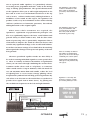
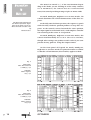
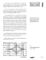
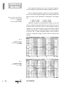
OPTIMIZER
parametric equalizer
Owner´s
Manual
Operation
.
Applications
.
Measurements
.
Specifications
©1994 SPL electronics GmbH
OPTIMIZER Owner´s Manual:
Operation, Applications,
Measurements, Specifications
Written by Paul White
and Hermann Gier
Manual version 1.1/94
The information in this document has been
carefully checked and is assumed to be correct.
However Sound Performance Laboratory (SPL
electronics GmbH) reserves the right to modify the
product described in this manual at any time.
This document is the property of SPL electronics
GmbH and may not be copied or reproduced in
any manner, in part or full without the authorization of SPL electronics GmbH.
Construction and circuit layout are subject to constant improvement and development. Changes
will be made without notice.
© 1994 SPL electronics GmbH
All rights reserved
CONTENTS
INTRODUCTION
4
INSTALLATION
7
CONNECTORS
7
OPERATING LEVEL
8
POWER SUPPLY
8
REAR PANEL
9
INPUT & OUTPUT SPECIFICATIONS
APPLICATIONS
9
10
MASTERING WITH THE OPTIMIZER
10
OPTIMIZER USED IN THE INSERTS
11
CONTROLS
12
FRONT PANEL
12
DUAL
13
ACTIVE
13
MASTER-EQ
13
PEAK
13
BOOST/CUT (+/-)
14
BANDWIDTH Q
15
FREQUENCY & FREQUENCY RANGE
16
OUTPUT
18
NOTCH
19
PARAMETRIC, HIGHPASS, BANDPASS, LOWPASS
20
PHASE MEASUREMENTS
22
NOISE MEASUREMENTS
24
COMMON MODE REJECTION
25
LIMITED WARRANTY
26
OPTIMIZER
3
INTRODUCTION
Congratulations on purchasing the Optimizer, one of the
most advanced and musical sounding parametric equalizer
currently available.
The Optimizer is a highly specialized and creative equali-
The OPTIMIZER is
designed for both
corrective and creative
applications, producing
effects impossible
to achieve using
conventional EQ.
Yet it remains
very simple to operate.
zer. In addition to familiar parametric functions, it features
a range of modes that enable it to perform Band-pass, Highpass, Low-pass and Notch filtering. As you would expect
from SPL - the company that developed the highly acclaimed
Vitalizer psychoacoustic equalizer - the Optimizer is no ordinary equalizer. It excels in both corrective and creative
applications and can produce many effects impossible to
achieve using conventional parametric equalizers. Yet it
remains very simple to operate.
Rather working out a theoretically ideal filter response on
paper, we have taken a more
creative tack, experimenting
directly with perceived sound
across a wide range of frequencies.
The design of the Optimizer has been based on proven
psychoacoustic principles and particular regard has been
taken to the way the human hearing system perceives
sound, at all stages of development. Rather working out a
theoretically ideal filter response on paper and trying to
emulate it, we have taken a more creative tack, experimenting directly with perceived sound across a wide range of frequencies.
The Optimizer provides a
powerful, flexible and easyto-operate means of equalizing sound.
The result of this creative work is an equalizer without
equal, both technically and artistically. Not only does it provide a powerful, flexible and easy-to-operate means of equalizing sound, but it boasts a noise level approaching the
theoretical minimum for advanced analogue circuit design
and a dynamic range even better than 18-bit digital systems.
The Optimizer produces a
smooth and linear phase response giving unsurpassed
musicality and sonic transparency
The filter circuits are based on an advanced state-variable filter topography which employs the "proportional-Q"
principle, active output stages for each filter-band and the
new "roll-off"-function to produce a smooth and linear phase
response giving the Optimizer unsurpassed musicality and
sonic transparency.
Rather than employing the standard "constant-Q" equalizer design commonly used in sound reinforcement and room
equalizers, the Optimizer works on the proportional-Q prin-
The advantage of
proportional-Q is that it
produces a more musical
result and fine tuning of the
filters is much easier.
4
ciple. The advantage of proportional-Q is that it produces a
more musical result and fine tuning of the filters is much
easier. The signal level is dependent of the bandwidth setting
- eliminating the need for constant level readjustment when
OPTIMIZER
INTRODUCTION
changing the filter settings. When broadening the bandwidth, the boost or cut will be reduced proportionally, so
that the subjectively perceived loudness remains constant.
The proportional-Q principle operates according to the way
our hearing system perceives sound.
With constant-Q equalizers there is often only a limited
range of useable settings. Sometimes this is so narrow, you
may wonder why the Q-control was not permanently fixed
at the point it sounds really good. Above that position it
often starts to sound harsh and peaky, and below with the
broad bandwidth, the sound is colored so you need to constantly re-set the boost/cut control. Not so with proportional
Q. The Q-control provides useable settings over the entire
range - giving you more versatility to be creative.
The Optimizer comprises four
identical filter stages which
can be configured for 4-band
mono, dual
2-band mono or 2-band stereo operation.
The Optimizer comprises four identical filter stages
which can be configured for 4-band mono, dual 2-band
mono or 2-band stereo operation. The front panel Dual
switch selects between 4-band or dual 2-band operation.
Both balanced XLR and unbalanced jacks are provided for
signal connections to and from the Optimizer. In Mono
mode, the filters are all connected in series, but the outputs
from each pair of filters remain accessible, so you can get
two differently filtered versions of the same signal which can
Each filter covers the same
enormous frequency range
10Hz to 23kHz.
be useful when you are creating special effects.
Each filter covers the frequency range 10Hz to 23kHz in
four switched frequency ranges to give fine frequency control, regardless of which part of the audio spectrum is under
process. Tuning the equalizer is very intuitive because the
frequency control law has been designed to match the characteristics of the human hearing system.
Being able to equalize starting at 10Hz with full
boost/cut power gives a new dimension for mixing and producing of subwoofer-compatible soundtracks.
The frequency response of the circuitry used in the audio
signal path exceeds the limits of human hearing by a considerable margin, effectively eliminating undesirable phase
shifts which, even when relatively small, can seriously
Each filter has its own mode
switch, so complex combinations of filter types can be
used in the same signal path.
impair the high frequency transparency of a less well-designed equalizer.
Each filter has its own mode switch to select between
High-pass, Low-pass, Band-pass and Parametric modes. In
OPTIMIZER
5
INTRODUCTION
addition each filter is equipped with a notch-filter. Selecting
The depth of the Notch
is in excess of 60dB
the Notch mode overrides the mode switch selector. So complex combinations of filter types can be used in the same signal path. For example, a parametric filter could be combined with a High- and Low-pass and Notch filter.
When working in Notch, Band-pass, High-Pass or LowPass modes, you have a choice of roll-off characteristics
which greatly extends the tonal capabilities of the
Optimizer. For example, in the Notch filter mode, you have
control over frequency and bandwidth and also over the
The Optimizer´s proportionalQ parametric filter design,
combined with its switchable
alternative filter modes, gives
you the flexibility to emulate
many different types of equalizer.
steepness of the sides of the notch. The depth of the Notch is
in excess of 60dB, providing an extremely high degree of
rejection compared with conventional parametric filters.
The subjective performance of certain classic equalizers is
highly dependent on the roll-off characteristics of their filter
circuitry. These equalizers sound excellent, but their circuit
topography imposes a rather fixed character on them. By
contrast, the Optimizer´s proportional-Q parametric filter
design, combined with its switchable alternative filter
The Boost/Cut control becomes the Gentle/Steep control
in Notch, Band-Pass, HighPass or Low-Pass modes.
Turning the control fully
anti-clockwise produces a
gentle roll-off while turning it
fully clockwise produces a
steep-sided response.
modes, gives you the flexibility to emulate many different
types of equalizer. In addition, you can set up further equalization types that even the best conventional equalizers cannot provide.
To keep the control layout simple, the BoostCut control
used in Parametric mode becomes the Gentle/Steep control
in Notch, Band-Pass, High-Pass or Low-Pass modes. Turning
the control fully anti-clockwise produces a gentle roll-off
while turning it fully clockwise produces a steep-sided response. If the control is set in the center position, the input
signal will cancel itself out completely, resulting in no output. Settings between the extremes and the center (null) position produce further useful variations in filter slope characteristic, though you may need to compensate for the level
loss incurred by settings close to the center position, by turning up the Output level control.
Selecting a steep filter characteristic produces a tightly
The Optimizer has active
output stages for each filter
increasing phase stability
dramatically.
focused, punchy tonal characteristic while choosing a gentle
slope produces a subtle change in tonality which has the
effects of adding a sonic gloss to the programme material.
We have invented a new all active output stage approach
to mixing filters: Commonly filters in parametric or graphic
equalizers mix passively resulting in increased phase distor-
6
OPTIMIZER
tion as each filter is added to the signal path. The Optimizer
overcomes this fault by using controllable all active output
INSTALLATION
stages resulting in a significantly improved phase response,
even when all four filters are linked up. The Output control
allows level adjustments to compensate for level changes due
to dramatic boost or cut adjustments.
The Optimizer is designed for standard 19” rack mounting and occupies 2U of rack space. Avoid mounting the unit
CONNECTORS
directly above power amplifiers or power supplies that radiate significant amounts of heat and always connect the mains
earth to the unit. Fibre or plastic washers may be used to prevent the front panel becoming marked by the mounting
The OPTIMIZER offers XLR
connectors for balanced operation and quarter-inch jacks
for unbalanced use.
bolts. Care must be taken when rack mounting the unit to
support the rear of the case, especially in mobile systems.
The Optimizer has connectors for unbalanced as well
balanced operation.
The XLR inputs and outputs are electronically balanced
on conventionally wired XLRs (pin 1 screen, pin 2 hot and
How to unbalance balanced
XLR connetors.
pin 3 cold). Unbalanced inputs and outputs are also available on mono, quarter-inch jacks.
OPERATING LEVEL
The signal connected to the jacks will always be preferred. A connection set-up with XLR´s and jacks can remain
connected. Unplugging the jacks will select the XLRs as primary inputs.
The XLR inputs and outputs can be unbalanced by
The operating level is
switchable between High and
Low (nominally 0dBu or 10dBv)
connecting the pin 3 to the ground terminal (pin 1). For proper wiring see figure below.
The operating level is switchable between High and Low
(nominally 0dBu or -10dBv). Choose the High position for all
pro-audio applications. Select the -10dB when the input sour-
OPTIMIZER
7
INSTALLATION
POWER SUPPLY
ce is not driving Optimizer´s filters sufficiently with the proviso that the Peak LED on the front panel is not continually
flashing. This will achieve equalization at a lower signal
level and will result in a more intensely processed sound.
Note: this level change also effects the signal when the filters
are in bypass, so you will loose direct comparability as the
listening level changes.
A Ground Lift switch is provided to assist in the elimination of ground loop problems.
Based around a toroidal transformer, the integral power
supply is designed to minimize induced hum and noise due
to the non existence of an air-gap. The primary voltage may
be selected between 230V/50Hz and 115V/60Hz by means of
a recessed slide switch on the rear panel.
A Ground Lift switch is provided to assist in the elimination of ground loop induced hum in complex installations. If
ground loop problems remain after activating the Ground
Lift switch, do not disconnect the mains earth. Instead try
disconnecting the signal screen at the end the cables that
connect the outputs of the Optimizer to the patchbay. If such
measures are necessary, balanced operation is recommended.
When the Ground Lift switch is set off, the circuit ground
is connected to the chassis ground.
The mains fuse should be rated at 800mA. A detachable
3-wire, U-ground power cord is included in the packaging.
8
OPTIMIZER
INSTALLATION
REAR PANEL
Input- & output
specifications
XLR - balanced:
Inputs:
Electronically balanced
(differential) transformerless
Impedance:
= 20kOhms
Nominal
input level:
+6dB
Input level
selector:
HIGH (0dB)
LOW(-10dB)
Maximum
input level:
+22dBm
Input peak:
LED indicates potential peak 3dB before
actual clipping.
Outputs:
Electronically balanced
(differential) transformerless
Impedance:
< 75 Ohms
Nominal
output level:
+6dB
Minimum
load ohms:
600 Ohms
Connectors:
Type: Neutrik NC 3 XLR
Pin wiring:
Pin 2 = high (+)
and
Pin 3 = low (-)
Jacks - unbalanced:
Inputs:
unbalanced
Impedance:
= 20kOhms
Nominal
input level:
0dB
Outputs:
Impedance:
Nominal
output level:
Minimum
load ohms:
unbalanced
< 600 Ohms
0dB
600 Ohms
Connectors:
Type: 1/4" Jacks (6,25mm)
Pin-Wiring:
Tip = high (+)
and
Sleeve = GND
GND-LIFTswitch:
off = chassis ground
on = ground lift
Power selector: 115V / 60Hz
230V / 50Hz
Fuse:
OPTIMIZER
800mA fast
9
SET-UP &
APPLCATIONS
PARAMETRIC SET-UP: To use the Optimizer as a dualchannel, parametric equalizer proceed as follows:
•
Set all filters to PARAMETRIC
•
Set to DUAL mode and ensure MASTER BYPASS is out.
•
Use filter ACTIVE control to set up one equalizer sec-
tion
For precise location of the frequency you want, set the
Boost/Cut control fully clockwise to provide
maximum boost.
at a time.
•
Select appropriate frequency range for each filter.
•
Set Q initially to midway point.
SETTING UP PROCEDURE: When trying to locate the precise frequency range requiring adjustment, set the Boost/Cut
(+/-) control fully clockwise to provide maximum boost. By
sweeping through the entire frequency range, it should be
easy to locate the precise frequency range that needs cutting
or boosting. Once found, the Boost/Cut control can be
backed off to provide the desired degree of cut or boost and
the Q setting adjusted by ear. Initially, it helps to bypass the
other equalizer sections so that you can work on each equalizer independently.
Use the Output to compensate
for level changes.
When the equalizer sections have been set independently,
they can be switched in simultaneously and further adjustments made if required. The Output control can be used to
restore any level change caused by intensive EQ cutting or
boosting.
For 4-band Mono use, set the Dual switch to out and proceed as described for stereo operation. In this mode, up to
four equalizer bands can be employed at one time. If fewer
are required, the unused bands should be individually bypassed using the appropriate Active button. If only two bands
are needed, it is best to use the Optimizer in Dual mode, as
this provides the shortest signal path between input and out-
The Optimizer is ideal for
equalizing stereo signals.
put.
Apart from the Optimizer’s more conventional applicati-
MASTERING
MULTI TRACK
RECORDER
WITH THE
OPTIMIZER
Master outInput filter
stages 1 and 3
10
OPTIMIZER
Output filter
stages 2 and 4
at treating stereo programme material - either at the mixing
stage or during post-production. The special characteristics
of the Optimizer allow you to add weight and punch to the
bass end of a mix or to lift harmonic detail out of the top
The Optimizer can produce
results as dramatic as subbass synths or harmonic
generators, but without side
effects.
end of a mix, without inadvertently adding harshness or
muddiness to the sound. In this respect, the Optimizer can
produce results every bit as dramatic as those achieved using
sub-bass synthesizers or harmonic generators, but without
SET-UP & APPLICATIONS
ons as a general studio equalizer, it is particularly effective
adding distortion to the original signal.
Where more subtle treatments are required, the
Optimizer’s exploitation of psychoacoustic principles ena-
The Optimizer improves the
focus, tonal balance and
general clarity of detail within a mix, with the bare
minimum of processing.
bles it to significantly improve the focus, tonal balance and
general clarity of detail within a mix, with the bare minimum of processing. This is particularly important when a
client wants to improve the sound of a mix but doesn’t want
to make any significant change to the overall tonal balance.
Even filter Cut/Boost settings of less than half a dB can bring
about significant changes in the perceived quality of the mix
being treated.
The more specialized equalizer modes are most likely to
be used for treating individual signals to create special effects. There is virtually no limit to the number of equalization
There is virtually no limit to
the number of equalization
effects you can create through
combining the various filters.
Proportional-Q and Roll-Off
allow processing without any
side effects.
effects you can create through combining the various filters.
Common studio effects such as ‘telephone’ or ‘transistor
radio’ sounds can be set up in moments, while the Notch filters can attenuate mains hum and rumble, reduce the level
of lighting buzz or even recreate vintage phasing effects.
Proportional-Q and Roll-Off will help processing without any
side effects. You also can use the Notch filters to synthesize a
pseudo stereo signal from a mono source, by placing not-
Optimizer´s extremely low
frequency response is ideal
for creating subwoofer com-
ches at different frequencies in the left and right channels.
MULTI TRACK
RECORDER
OPTIMIZER
USED IN THE
Master out-
INSERTS
Insert send 2
Insert send 1
Input filter
stages 1 and 3
Insert return 1
Output filter
stages 2 and 4
Insert return 2
OPTIMIZER
11
CONTROLS
Start
positions:
Peak-LED illuminates 3dB
before clipping
FRONT PANEL
Boost/cut
(+/-)/
Roll-off
(0)
Bandwidth
(1)
The OPTIMIZER is
equipped with four filter
bands which can be used either in a 4-band mono
or dual 2-band stereo
configuration.
Freq. range
(1. or 4.
band)
Filter mode
switch choose
parametric
Dual depress
for stereo
applications
Frequency
(center)
All controls and switch functions are incorporated into
each of the four filter bands
except Master-EQ and Dual
switch.
Notch (off)
Output
(0dB)
Active (on)
Master EQ
(on when
using XLRs)
12
OPTIMIZER
trally mounted Dual switch selects between stereo 2-band
DUAL
and mono 4-band operation. In Dual mode, a green status
LED illuminates. For use with stereo signals such as complete
CONTROLS
All four channels of the Optimizer are identical. The cen-
mixes or sub-mixes, the Optimizer should be switched to
Dual mode and both sets of channel controls set to the same
position. Equalizers 1 and 2 work as a pair as do 3 and 4.
However, in Mono mode, (Dual button out), the signal is
automatically routed from the output of equalizer 2 to the
input of equalizer 3, placing all four equalizer sections in
In mono mode the signal is
routed from output 2 to the
input of 3, this places all four
sections in series. You can
tap out after 2 as well as 4,
you can use this feature for
blends on the mixer.
series. Because the signal routing is controlled by the Dual
switch and not by normalising connectors, no additional
measures need to be taken when using the Optimizer with a
patchbay system.
In Mono mode, both sets of outputs continue to function
normally, allowing one signal to be tapped off after passing
through filters 1 and 2 and another to be taken after passing
through all four filter sections.
The Active switch is used to switch the individual equali-
ACTIVE
zer section in and out of the signal path. The Active switch
operates as an electronic bypass. Take care when switching
the Active function in and out, when listening at high moni-
Each of the four OPTIMIZER
filters is equipped with an
individual bypass switch.
tor levels. Depending on the EQ settings a click may occur at
the moment of switching, so dim or mute the monitors if
necessary.
MASTER EQ
The Master EQ switch is a hard relay bypass which links
the input socket directly with the output socket to bypass all
filters by pressing just one button. Note: this only applies
The Master-EQ switch hard
relay bypasses all filters with
balanced XLR connectors.
when using the balanced XLR inputs and outputs in stereo
operation. When working with unbalanced signals, this
switch has no effect. The switch has an integral red lamp
which illuminates when Master-EQ is active.
To increase operation reliability especially in Live or OnAir situations, the Optimizer monitors the power supply´s
primary and secondary voltages and switches automatically
to hard bypass once certain tolerances have been exceeded.
PEAK
A peak LED is fitted to each EQ section, which flashes at
approximately 3dB below the level at which clipping occurs.
If the Peak LED constantly flashes, the input to the equalizer
OPTIMIZER
The Peak LEDs flash at
approximately 3dB below the
actual clipping level.
13
CONTROLS
BOOST/CUT
The Boost/Cut control (+/-) is has two functions depending on the mode you are working in. If the rotary switch is
set to Parametric, the control acts as a conventional
&
Boost/Cut control providing a range of plus or minus 12dB.
ROLL-OFF
In Notch, Band-pass, High-Pass or Low-Pass modes, the
control determines the roll-off characteristics of the filter resThe Boost/Cut controls has
two distinct functions depending on the mode you are in.
Boost and Cut as well as rolloff
characteristics.
ponse.
In the fully anti-clockwise position, the response is gentle
while the fully clockwise position produces a steep filter response. As the control is moved towards the center position,
the input signal is nulled with itself, with complete cancellation occurring at the center or zero position.
In Notch, Band-pass, High-Pass or Low-Pass modes, this
control would normally be set at or close to its extremes,
though other settings can produce useful results if you compensate for any gain loss using the Output control.
On the front panel all legends for Notch, Band-pass,
High-Pass or Low-Pass modes are printed in italics to indicate that the roll-off function (also in italics) applies to them.
Fig. 1:
Dotted line:
Max. boost and cut
+/-12dB; Q = 1,5
Solid line:
Phase response
at Q = 1,5
Fig. 2:
Dotted line:
Max. boost and cut
+/-12dB; Q = 0,2
Solid line:
Phase response
at Q = 0,2
14
OPTIMIZER
BANDWIDTH
"Q"
Notch or Band-Pass filters. In the context of the High and
Low-Pass settings, the Q control influences the cut-off cha-
CONTROLS
The Q control sets the bandwidth of the Parametric,
racteristics of the filter. Q is variable from 1.5 to 0.2.
The Q is set to "high Q" (1.5) when turned fully counter
clockwise. The influenced range covers approximately 0.75
octaves. Turning the Q control fully clockwise selects "low Q"
values (0.2) covering approximately 5 octaves.
The OPTIMIZER utilizes the proportional-Q principle,
also known as "variable Q". The amplitude varies depending
on the Q setting. Using low-Q values, automatically readjusts
the amount of boost or cut selected to keep the subjectively
perceived laudness constant. With constant-Q equalizers
there is often only a limited range of useable settings.
With proportional-Q the signal level is dependent of the
bandwidth setting - eliminating the need for constant
level readjustment when
changing the filter settings.
Sometimes this is so narrow, you may wonder why the Q
control was not permanently fixed at the point it sounded
really good. Above that position it often starts to sound
harsh and peaky, and below with the broad bandwidth, the
sound is colored so you need to constantly re-set the
boost/cut control. Not so with proportional-Q. The Q control
provides useable settings over the entire range - giving you
more versatility to be creative.
EQ adjustments with proportional-Q sound a lot more
musically related and offer a greater range of possible Qchoices that really sound good and appropriate
Figure 3 shows curves within varying Q-adjustments but
with constant boost and cut.
Fig. 3:
Q-values are between 0,2 and
1,5 at maximum boost and
cut of +/- 12dB.
OPTIMIZER
15
CONTROLS
FREQUENCY &
FREQ. RANGE
The frequency control (Hz) varies the filter frequency
over the range selected with the Frequency Range switches.
The two Frequency Range switches are used in combination to select four frequency ranges. The switch positions are
shown clearly on the Optimizer’s front panel. The ranges
There is a huge overlap in the
frequency range to really
allow you
to zoom in.
For general use 1 and 4.
are:
1. 10Hz to 2.4kHz
2. 16Hz to 3.3kHz
3. 34Hz to 7.1kHz
4. 112Hz to 23kHz.
Sufficient overlap is provided between ranges so you can
select a suitable range that allows the Hz control to be used
near the center of its travel. There is also enough overlap to
equalize over the entire frequency range from 10Hz to 23kHz
when the Dual mode is selected. In practice you will normally only use the 1. and 4. frequency range, as the overlap is
2,288 Hz. Frequency ranges 2 and 3 can be used for fine
tuning.
Fig. 4:
1. frequency range
from 10Hz to 2400Hz
at +/-12dB
Fig. 5:
2. frequency range
from 16Hz to 3300Hz
at +/-12dB
16
OPTIMIZER
CONTROLS
Fig. 6:
3. frequency range
from 34Hz to 7100Hz
at +/-12dB
The frequency control (Hz) will set the center-frequency
Fig. 7:
4. frequency range from
112Hz to 23000Hz
at +/-12dB
when working in Parametric, Band-pass and Notch mode
where-as in Low-pass mode it will determine the upper, and
in High-pass the lower corner frequency.
Below is a chart for pinpointing the exact frequencies.
The scale has 11 marks. The center position (12 o´clock) is
number 6:
Band 1
Band 2
Band 3
Band 4
1
10,789
15,778
32,436
110,74
2
19,819
24,895
79,621
195,90
3
113,85
166,49
195,90
1084,7
4
179,64
283,45
590,24
1918,9
5
243,46
356,03
778,09
2370,6
6
305,82
482,53
957,26
3161,1
7
414,48
606,12
1261,9
4204,5
8
561,75
886,36
1782,5
5592,3
9
886,36
1398,5
2697,3
9212,4
OPTIMIZER
Chart for precise adjustment
of frequencies with the Hz
control.
Numbers 1-11 representthe
scale marks around the pot.
The center position is mark
#6.
17
CONTROLS
OUTPUT
10
2045,1
2990,7
6180,6
20185
11
2380,5
3481,7
7096,3
21677
All frequencies in Hertz (Hz).
The output control sets the output level of the filter secA unique feature is the individual filter output control.
You can set up the individual
filter exactly, then feed in
just the right amount.
tion. You can adjust the gain from -80dB to +5dB.
Output operates in all filter modes and can be used to
correct the signal level if the next equalizer section is being
overloaded or under driven.
The Output control can also be used to compensate for
level changes due to cutting or boosting. This can be very
helpful in situations where extensive equalization was used
to match the equalizers and original signal.
If you are using two or more sections of the Optimizer on
one signal you can use the Output control to boost the output levels where cuts have been made and to attenuate them
where boosts were needed.
The Optimizer features active
output stages resulting in a
significantly improved
phase linearity.
This also compensates for
level changes.
The Output control is a feature that you will not find on
any other parametric equalizer.
We have created a new approach by using active output
stages to mix filters: Commonly filters in parametric or graphic equalizers mix passively resulting in increased phase
distortion as each filter is added to the signal path. The
Optimizer overcomes this fault by using controllable all
active output stages resulting in a significantly improved
Fig. 8:
Two frequency curces with
centerfrequency at 1kHz (Q =
0,2 and Q = 1,5) are boosted
by +5dB with the Output
level control.
phase response, even when all four filters are linked up. The
Output control allows level adjustments to compensate for
18
OPTIMIZER
level changes due to dramatic boost or cut adjustments.
The Notch switch puts the filter into notch filter mode. It
CONTROLS
NOTCH
The Notch filter provides
attenuation of more than
60dB per filter stage.
It is variable in Q and rolloff.
provides a deep cut of over 60dB which can be varied in frequency to address any part of the audio spectrum, providing
in excess of 60dB of attenuation at the center frequency. The
Q control varies the bandwidth of the notch from narrow to
wide, while the roll-off control may be used to select either a
steep or gentle roll-off at each side of the notch.
The Notch filter is useful in corrective applications where
it can be used to attenuate mains hum and similar ‘pitched’
interference. Because mains hum contains harmonics, better
results are often achieved by using two Notch filters
Create a pseudo stereo
image from a mono source
by splitting the signal and
applyind different notches.
together, one tuned to the fundamental frequency and one
an octave higher. The narrower the notch, the less the wanted sound will be affected by the filtering. Notch filtering
also can be used to simulate phasing by manually sweeping
Fig. 9:
Notch:
Curve 1: Q = 1,5;
Roll-Off = steep
Curve 2: Q = 0,2;
Roll-Off = steep
Fig. 10:
Notch:
Curve 1: Q = 1,5;
Roll-Off = gentle
Curve 2: Q = 0,2;
Roll-Off = gentle
OPTIMIZER
19
CONTROLS
Fig. 11:
Notch:
Curve 1: Q = 1,5;
Roll-Off = steep
Curve 2: Q = 0,2;
Roll-Off = steep
Curve 3: Q = 1,5;
Roll-Off = gentle
Curve 4: Q = 0,2;
Roll-Off = gentle
a notch across the audio spectrum. A further creative use is
to create a pseudo stereo image from a mono signal by splitting the signal and applying different notches to each of the
two channels. If these two channels are then panned left and
right in the final mix, it creates an illusion of space. The
position, number and width of the notches must be fine
PARAMETRIC,
HIGHPASS,
BANDPASS,
LOWPASS
tuned by ear.
Curves 2 and 3 show an alomst identical response in Fig.
11. Nevertheless there is an audible difference that is much
greater than shown in the graph.
The 4-way rotary switch sets the equalizer function
(Parametric, Low-pass, High-pass, Band-pass), although if
you select Notch this overrides whatever other equalizer
mode has been selected.
When using these three modes you should be aware that
the filters are connected in series, and depending on the filter types and settings, it is possible to set up a situation
where there is no output at all. For example, if one filter is
set as a High-pass filter with a cut-off frequency of 1kHz,
everything below 1kHz will be attenuated. If this signal is
now fed into the next stage, set as a Low-pass filter, with a
cut-off frequency of 500Hz, it will pass only signals below
500Hz. As the first filter’s output contains little or nothing
below 1kHz the result is very little signal.
For this reason, Band-pass filters are often used on their
own while High-pass and Low-pass are usually used as a pair
to provide control over the extremes of the audio spectrum.
Conversely, they can be used to ‘bracket’ a narrower section
20
OPTIMIZER
CONTTOLS
Fig. 12:
Curve 1:
Low-pass, Q = 1,5;
Roll-Off = steep
Curve 2:
High-pass; Q = 1,5;
Roll-Off = steep
Curve 3:
Band-pass; Q = 1,5;
Roll-Off = steep
of the audio spectrum to contrive a bandpass filter for the
production of ‘telephone’ effects and similar treatments.
In the High-pass and Low-pass modes, the Q control
changes the filter characteristic from over damped to under
damped, with the higher Q settings producing a tighter,
Fig. 13:
Curve 1:
Low-pass, Q = 1,5;
Roll-Off = gentle
Curve 2:
High-pass; Q = 1,5;
Roll-Off = gentle
Curve 3:
Band-pass; Q = 1,5;
Roll-Off = gentle
more focused sound.
Fig. 14:
Curve 1:
Low-pass; Q = 0,2;
Roll-Off = gentle
Curve 2:
High-pass; Q = 0,2;
Roll-Off = gentle
Curve 3:
Band-pass; Q = 0,2;
Roll-Off = gentle
OPTIMIZER
21
Fig. 15:
Curve 1:
Low-pass, Q = 1,5;
Roll-Off = gentle
Curve 2:
Low-pass; Q = 1,5;
Roll-Off = steep
PHASE
MEASUREMENTS
The following measurements show that the Optimizer´s
phase response is very stable at high amplitudes.
The doted line in fig. 16 illustrates the frequency response
from 0Hz to 200kHz for two combined equalizers (band 1 and
2). The solid line shows the phase reponse with only 2° divertion at 20kHz!
A broad frequency range has become a major demand for
Fig. 16:
Doted line :
Frequency response
Solid line :
Phase response
Measurements at Q = 1.0;
Frequency = 1kHz; Boost/Cut
= 0dB;
Frequency range:
34-7100Hz
22
OPTIMIZER
PHASE MEASUREMENTS
Fig. 17:
Curve 1:
Frequency response; 1kHz
Curve 1a :
Phase response
Curve 2:
Frequency response;
Notch 1kHz
Curve 2a :
Phase response
Measurements at Q = 1.0;
Boost/Cut = +12dB
equalizers in modern recording technology. The Optimizer
has an extremely broad frequency response from 0Hz to
200kHz that guaranties that the Optimizer´s filters operate
with maximum tonal flexibility and without technically
induced limitations.
Fig. 18:
Band-pass
Dotted line:
Frequency response
Solid line:
Phase response
Messungen bei Q = 1.5;
Frequenz = 1kHz;
Boost/Cut = +12dB
Fig. 19:
Four filter stages in series
Dotted line:
Frequency response
Solid line:
Phase response
Boost/Cut = 12dB
OPTIMIZER
23
NOISE
MEASUREMENTS
Fig. 20:
Noise Measurement
"A" WTG: -92,56dB
Boost/Cut = 0dB;
Fig. 21:
Noise Measurement
"A" WTG: -108,79dB
Boost/Cut = 0dB;
Master-EQ: Bypass
Fig. 22:
Noise Measurement
THD & Noise
Boost/Cut = +12 dB;
Bandwidth Q = 1.0;
Frequency = 1kHz:
0.035%
24
OPTIMIZER
NOISE MEASUREMENTS
Fig. 22:
Noise Measurement
CCIR 468: -83dB
Boost/Cut = +12 dB;
Bandwidth Q = 1.5;
Frequency = 1kHz
Fig. 23:
Noise Measurement
CCIR 468: -84dB
Boost/Cut = 0 dB;
Bandwidth Q = 1.5;
Frequency = 1kHz
COMMON MODE
REJECTION
Fig. 24:
Common Mode Rejection of
differential XLR Inputs
Frequency range:
20Hz to 100kHz.
CCMR: -76,73dB
OPTIMIZER
25
LIMITED
WARRANTY
SPL electronics GmbH (hereafter called SPL) products are
warranted only in the country where purchased, through the
authorized SPL distributor in that country, against defects in
material or workmanship. The specific period of this limited warranty shall be that which is described to the original retail
purchaser by the authorized SPL dealer or distributor at the time
of purchase.
SPL does not, however, warrant its products against any and
all defects:
1) arising out of materials or workmanship not provided or
furnished by SPL, or 2) resulting from abnormal use of the product or use in violation of instructions, or 3) in products repaired
or serviced by other than authorized SPL repair facilities, or 4) in
products with removed or defaced serial numbers, or 5) in components or parts or products expressly warranted by another
manufacturer. SPL agrees, through the applicable authorized
distributor, to repair or replace defects covered by this limited
warranty with parts or products of original or improved design,
at its option in each respect, if the defective product is shipped
prior to the end of the warranty period to the designated authorized SPL warranty repair facility in the country where purchased, or to the SPL factory in Germany, in the original packaging
26
or a replacement supplied by SPL, with all transportation costs
and full insurance paid each way by the purchaser or owner.
All remedies and the measure of damages are limited to the
above services. It is possible that economic Loss or injury to person or property may result from the failure of the product; however, even if SPL has been advised of this possibility, this limited
warranty does not cover any such consequential or incidental
damages. Some states or countries do not allow the limitations or
exclusion of incidental or consequential damages, so the above
limitation may not apply to you.
Any and all warranties, express or implied, arising by law,
course of dealing, course of performance, usage of trade, or
otherwise, including but not limited to implied warranties of
merchantability and fitness for particular, are limited to a period of 1 (one) year from either the date of manufacture. Some states or countries do not allow limitations on how long an implied
warranty lasts, so the above limitations may not apply to you.
This limited warranty gives you specific legal rights, and you
may also have other rights which vary from state to state, country to country.
OPTIMIZER
SOUND PERFORMANCE LABORATORY
SPL electronics GmbH Hauptstrasse 59 D-41372 Niederkrüchten
P.O.Box: Postfach #1227 D-41368 Niederkrüchten
Tel. +49-(0)2163-8761 Fax +49-(0)2163-83028