1
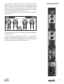
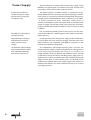
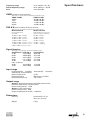
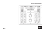
Dual Channel Microphone Preamplifier
Manual
Model 9523
MikeMan
Manual
by Hermann Gier, Paul White & Paul Lentzen
Version 2.0 – 10/1998
The information in this document has been
carefully verified and is assumed to be
correct. However Sound Performance
Laboratory (SPL) reserves the right to modify
the product described in this manual at any
time. Changes without notice. This document
is the property of SPL and may not be copied
or reproduced in any manner, in part or full
without the authorization of SPL.
Limitations of Liability:
In no event will SPL be liable for any
damages, including loss of data, lost profits,
cost of cover or other special, incidental,
consequential or indirect damages arising
from the use of the unit, however caused and
on any theory of liability. This limitation will
apply even if SPL or an authorized dealer has
been advised of the possibility of such
damage.
SPL electronics GmbH
P.O. Box 12 27
D- 41368 Niederkruechten, Germany
Tel + 49 - 2163 - 9 83 40
Fax + 49 -2163 - 98 34 20
E-Mail: [email protected]
www.spl-electronics.com
SOUND PERFORMANCE LAB
© 1998 SPL electronics GmbH. All Rights Reserved.
Model 9523
Foreword................................................................................................... 3
Introduction............................................................................................. 4
Operation Safety..................................................................................... 4
Connections............................................................................................. 5
Contents
Control Elements
MIC GAIN .................................................................................................. 6
PHASE REVERSE ...................................................................................... 6
-35 dB ........................................................................................................ 7
48 V - PHANTOM POWER ..................................................................... 7
PPM METER .............................................................................................. 7
Power Supply........................................................................................... 8
Specifications........................................................................................... 9
Warranty ...................................................................................................10
Foreword
Dear customer,
Thank you for the confidence you have shown towards SPL electronics GmbH by purchasing the SPL MIKEMAN. You have decided
to use a tool of high performance which sets you in the position
to have faster success and a better sound quality in your music
productions.
As a typical SPL unit the MIKEMAN combines exemplary specifications and high manufacturing standard with excellent sound
quality to provide you a precious component for studio and P.A.
purposes. Please read this manual carefully to ensure you have all
the information you need to use the MIKEMAN. We wish you every
success.
Your Sound Performance Laboratory-Team
I would like to start with my thanks to all our staff, who created
what is to be described here. The importance of their exceptional
qualification and talents can´t be overestimated. But the biggest
thanks I owe their unbelievable engagement, creativity and
productivity in realizing our projects.
Thanks
Our products are often tested and compared in many publications and by our customers themselfs and constantly valued with
best results.
I would like to pass on this broad appreciation to those, who
deserve it – my excellent colleagues.
Hermann Gier
3
Introduction
The recording industry has gone through some dramatic
changes in the past years. The home recording market produces
professional results with modest investments. Mainly inexpensive
mixing consoles with lots of channels and 8-bus-option are being
used. High class filtering and microphone preamplification are
not incorporated in these systems. The “direct to DAT” recording
philosophy has created another growing market. Sampling and
direct cutting through quality mic preamps has become popular.
The MIKEMAN is the ideal choice for both recording situations. It is
the cost-effective entry into high performance preamplification
and ideally suited to partner your favorite mic in getting the best
possible performance on tape. It improves the sonic quality of
small mixing consoles with two channels of superior preamplifiaction and it is the ideal tool for “direct to DAT” applications.
The MIKEMAN is a dual channel microphone preamplifer with
excellent noise and CCMR specs. It has a large input headroom
(+26,5 dB), which makes limiting a less important issue.
Microphone and line level signals can be preamplified up to
+72 dB. Activating the padding switch attenuates the preamplifier
stage by -35 dB. The superior phantom power supply for
condensor microphones is also ideal for old tube microphones
which need a very stable and clean +48 V phantom powering.The
Phase Reverse switch is used to change the polarity of the microphone. PPM-meters displaying output values between -18 dB and
+9 dB are also incorporated. The input and output stages can
optionally be equipped with beyerdynamic transformers.
Operating Safety
Important security advices
The housing of the MIKEMAN has the standard 19" EIA format and
occupies 1 unit (1 U = 44 mm) in your rack. When installing the
unit in a 19" rack, the rear side of the unit needs some support,
especially in a touring case. The MIKEMAN should not be installed
near units which produce strong magnetic fields or extreme heat.
Do not install the MIKEMAN directly above or below power amplifiers or digital processors. If possible, the MIKEMAN should be
placed in an »analog rack« where the majority of (or all) the
equipment installed is analog. This eliminates problems which
could result from interfering high-frequency signals such as clock
frequencies, MIDI or SMPTE control signals.
Check that the voltage details quoted on the back panel are the
same as your local mains electricity supply. Use a minus (-)
screwdriver to set the voltage selector to the voltage for the area
in which the unit will be used.
Never cover up the ventilation slots on the top of the unit. If,
during operation, the sound is interrupted or indicators no longer
illuminate, or if abnormal odor or smoke is detected, or if water is
spilled on the unit, immediately disconnect the power cord plug
and contact your dealer or an authorized service center.
Only clean your MIKEMAN with a soft, lint-free cloth. Use only
standard cleaning agents. Never use alcohol or paint thinner,
because they may damage the finish.
4
The MIKEMAN is equipped with two electronically balanced,
female 3-pole XLR sockets to connect two microphones or a line
signals. The outputs of the MIKEMAN are designed balanced on
male XLR sockets as well as unbalanced on 1/4“ jacks.The outputs
can be used parallel to each other. This means that two output
signals can be produced from one input signal.
Connections
The following diagram shows how to unbalance balanced
wiring correctly:
Condenser microphones with 48 V phantom power can not be
used unbalanced.
Rearfront MIKEMAN, Model 9523
Both output stages operate in parallel, so it is possible to
connect two different destination units simultaneously, for
example to record to two different media at the same time or split
the output between a mixer and effects processor.
5
Control Elements
5
2
1
Mic Gain
1
3
4
The preamplifier stage of the MIKEMAN is based on the SSM 2017
semiconductor. The strengths of this particular component are its
extremely low noise and distortion characteristics. Unlike discretely designed circuits, the SSM 2017 has 64 transistor functions
(discretely up to 24), thus achieving a very high common mode
rejection.
Preamplification of the input signal is determined by the MIC
GAIN control. The control range of the preamplification values
ranges from +22 dB to +72 dB. The maximum amplification value
specified is a minimum value. The preamplifier stage provides up
to +75 dB. This value can be lower, depending on the tolerance of
the potentiometer, but it never falls below a value of +72 dB.
The maximum input level is +25,7 dB! This high input capability
reduces the need of limiting.
When setting the MIC GAIN value, take note of the transducer
type (condensor or dynamic microphone) and the free-field
transmission factor of the microphone type. The sound pressure
level of the sound source to be recorded, the distance to the
microphone and the room acoustics are other factors which also
have to be taken into account when setting the MIC GAIN potentiometer. The free-field transmission factor of a dynamic microphone is around 2 mV/Pa, that of a condensor microphone can be
up to 20 mV/Pa, which equals an increase in the output level of
20 dB.
Phase Reverse
2
Pressing the phase switch (PHASE REVERSE) inverts the polarity
of the microphone signal. When the switch has not been pressed
(status LED is off ), the polarity is »in phase«. Pressing the switch
means that the polarity is »out of phase«.
Phase inversion can be used for a number of different reasons:
1. If, for example, the microphone signal of a singer or speaker is
preamplified in the MIKEMAN and the monitor signal is folded back
to the headphones, the singer or speaker cannot hear himself
very well. Pressing the phase switch inverts the polarity of the
microphone and consequently, of the headphone signal, and the
singer or speaker can then hear himself on his headphones
without having to increase the level.
6
2. The phase inversion feature is also very useful when the polarity of the XLR input jack has to be inverted to match the polarity
of the microphone or the microphone cable.The pin assigment of
the XLR connector is as follows: Pin 2 = hot (+) and Pin 3 = cold (-).
3. Sometimes it is desirable to swop the polarity of a microphone because of the sound.
The MIKEMAN can also be used as a gain-on amplifier for line
signals. The input sensitivity of the preamplifier stage is reduced
by 35 dB by pressing the -35 dB switch. The corrected preamplification value on the MIC GAIN control can be ascertained by subtracting 35 dB from the value set on the potentiometer.
3
-35 dB
Condensor microphones require a supply voltage of 48 V DC
which supplies the microphone via the balanced audio lines (pins
2 and 3). When the supply voltage is switched on, a phantom
circuit is formed whereby the 48 V DC supply voltage is applied
simultaneously to the two supply lines (+/-) of the microphone
and fed back via the cable screen.
4
48 V
Phantom Power
Phantom power
according to
DIN 45 596 / IEC 268-15
There is no DC voltage between the two modulation lines which
is why dynamic microphones can be used when the phantom
voltage is switched on, without this doing the microphones any
harm.
The influences of noise voltages which can superpose the DC
supply voltage such as hum loops and parasitic currents in the
cable screen are reduced by the phantom power supply.
Moreover, this type of connection is particularly resistant towards
RF.
As there is no potential difference between the +/- supply lines,
the connection technique of the phantom supply is compatible
with moving coil and ribbon microphones.
All microphones with balanced floating output, i.e. also microphones equipped with tubes can be used when the phantom
voltage is switched on.
WARNING: It is essential to switch the phantom supply off if
other types of microphones are used. A line signal source or
an unbalanced microphone may only be used if the phantom
supply is switched off.
The output peak levels (PPM values) are indicated on the LED
display in steps of 3 dB from -18 dB to + 9 dB.
5
PPM Meter
7
Power Supply
A stable and well-filtered
toroidal-core power supply
provides the basis for good
sound processing.
Special attention has been paid to the power supply of the
MikeMan. The power pack is the heart of any unit, and the more
accurately it works, the more this improves results.
The power supply is installed around a toroidal-core transformer which does not cause any electronic humming or mechanical sounds as a result of its minimum leakage field. The primary
voltage can be switched between 230 V / 50 Hz and 115 V / 60 Hz.
A 3-pole standard IEC mains connection socket serves to
connect a detachable 3-pole mains lead which is included in the
scope of supply. Transformer, power cable and mains connector
comply with the requirements of VDE, UL and CSA.The fuse rating
is 200 mA.
8
The GND LIFT switch helps to
remedy hum loops.
The connection between ground and housing can be separated via the GND LIFT switching option. Hum loops can be remedied in this way.
Ample filtering, smoothings
and calibrations make for
stable, constant service
voltage.
On the secondary side of the power supply, an RC combination
is used to filter out noise and hum voltages from the mains side.
Both half-waves are smoothed with 2000 mF capacitors in the
positive and negative voltage path.
The phantom supply voltage is
from a separate power supply
with sophisticated filtering
and selected components.
An independent, self-contained power pack is used for the
phantom power supply. It obtains unregulated AC voltage from 2
x 25 V coils in the transformer. This results in +/- 22.5 V DC via
bridge rectifiers which are filtered with 1000 mF. The DC voltage
is adjusted to exactly 48 V in the switching power supply (LM 311)
downstream. It is then smoothed again and stabilized. The power
supply current flows to the intrusion point via the PCB. An RC
combination stabilizes the power supply again at this point. Two
medicinal 6.81 kW resistors with a tolerance of only 0.1% are used
as bridging resistors.
Frequency range
Overall frequency range
E.I.N.
15 Hz- 40 kHz +/- 0,1 dB
10 Hz-100 kHz +/- 0,5 dB
126,6 dBm/dBu
Specifications
CMRR (common mode rejection)
(Measuring set-up: load ohms 150 W, 0dB, measured at XLR-output)
CMRR -20 dBu
100 Hz:
1 kHz:
10 kHz:
20 kHz:
CMRR -60 dBu
-80 dBu-80 dBu
-80 dBu-80 dBu
-73 dBu-80 dBu
-68 dBu-80 dBu
THD & N (total harmonic distortion & noise)
(Measuring set-up: load ohms 150 W, measured at XLR-output)
Measurement A
Measurement B
Varying amplifications
up to 0dBu
60dB amplifications; increase of
generator output in 10dB steps
-60 dBu to 0 dBu = 0,064 %
-50 dBu to 0 dBu = 0,028 %
-40 dBu to 0 dBu = 0,017 %
-30 dBu to 0 dBu = 0,015 %
-20 dBu to 0 dBu = 0,062 % (-35 dB activ)
-10 dBu to 0 dBu = 0,025 % (-35 dB activ)
0 dBu to 0 dBu = 0,017 % (-35 dB activ)
-60 dBu = 0,064 %
-50 dBu = 0,058 %
-40 dBu = 0,018 %
-30 dBu = 0,006 %
-20 dBu = 0,002 %
-10 dBu = clipping
Signal to noise
(Measuring set-up: load ohms 150 W, measured at XLR-output)
amplification CCIR-469-2
72 dB
-55,85 dBqp
60 dB
-60,66 dBqp
50 dB
-68,57 dBqp
40 dB
-73,11 dBqp
30 dB
-74,79 dBqp
with -35 dB Pad:
20 dB
-62,56 dBqp
10 dB
-69,83 dBqp
A unweighted
-60,07 dB
-69,75 dB
-77,55 dB
-81,75 dB
-83,18 dB
-71,85 dB
-78,68 dB
Input stage
Instrumentation amplifier, electronically balanced
(differential), transformerless
Nominal input level
+6 dB
Input impedance
200 Ohm to 1,2 kOhm
headroom before clip
+25,72 dBu
Output stage
Output 1: XLR, Instrumentation amplifier, electronically
balanced (differential), transformerless,
Nominal output level +6 dB
Output 2: Jack, unbalanced
Nominal output level 0 dB
Output impedance (XLR/Jack) < 600 Ohm
Dimensions
Housing
Standard EIA 19"/1U,
482 x 44 x 237 mm
Weight
3,2 kg
9
Warranty
SPL electronics GmbH (hereafter called SPL) products are
warranted only in the country where purchased, through the
authorized SPL distributor in that country, against defects in
material or workmanship. The specific period of this limited
warranty shall be that which is described to the original retail
purchaser by the authorized SPL dealer or distributor at the time
of purchase.
SPL does not, however, warrant its products against any and all
defects:
1) arising out of materials or workmanship not provided or
furnished by SPL, or 2) resulting from abnormal use of the
product or use in violation of instructions, or 3) in products
repaired or serviced by other than authorized SPL repair facilities,
or 4) in products with removed or defaced serial numbers, or 5) in
components or parts or products expressly warranted by another
manufacturer.
SPL agrees, through the applicable authorized distributor, to
repair or replace defects covered by this limited warranty with
parts or products of original or improved design, at its option in
each respect, if the defective product is shipped prior to the end
of the warranty period to the designated authorized SPL warranty
repair facility in the country where purchased, or to the SPL
factory in Germany, in the original packaging or a replacement
supplied by SPL, with all transportation costs and full insurance
paid each way by the purchaser or owner.
All remedies and the measure of damages are limited to the
above services. It is possible that economic loss or injury to
person or property may result from the failure of the product;
however, even if SPL has been advised of this possibility, this
limited warranty does not cover any such consequential or incidental damages. Some states or countries do not allow the limitations or exclusion of incidental or consequential damages, so the
above limitation may not apply to you.
Any and all warranties, express or implied, arising by law, course
of dealing, course of performance, usage of trade, or otherwise,
including but not limited to implied warranties of merchantability and fitness for particular, are limited to a period of 1 (one) year
from either the date of manufacture. Some states or countries do
not allow limitations on how long an implied warranty lasts, so
the above limitations may not apply to you.
This limited warranty gives you specific legal rights, and you
may also have other rights which vary from state to state, country
to country.
SPL electronics GmbH, D-41372 Niederkruechten, Germany
10