1
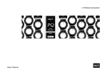
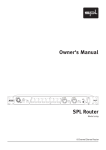
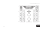
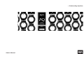
> PQ Recording Equalizer
Owner‘s Manual
PQ Recording Equalizer, Model 2377
Owner‘s Manual
Owner‘s Manual V 1.0, 5/2004
Software version 016
R & D: Wolfgang Neumann
The information in this document has been carefully verified and is assumed to be
correct. However Sound Performance Lab (SPL) reserves the right to modify the
product described in this manual at any time. Changes without notice. This document
is the property of SPL and may not be copied or reproduced in any manner, in part or
full without the authorization of SPL.
Limitations of Liability:
In no event will SPL be liable for any damages, including loss of data, lost profits,
cost of cover or other special, incidental, consequential or indirect damages arising
from the use of the unit, however caused and on any theory of liability. This limitation will apply even if SPL or an authorized dealer has been adviced of the possibility
of such damage.
Sound Performance Lab
SPL electronics GmbH
P.O. Box 12 27, D- 41368 Niederkruechten, Germany
Phone +49 2163 983 40
Fax +49 2163 983 420
Email: [email protected]
www.soundperformancelab.com
© 2003 SPL electronics GmbH. All rights reserved. Technical specifications and appearance are subject to change
without notice.
2
Content
Introduction ...................................................................................................
3
Installation ....................................................................................................
4
Technology .....................................................................................................
5
Fuctions and Operation ...................................................................................
6
Rear Panel/Connections, External Power Supply ............................................
8
Specifications ................................................................................................
9
Warranty .........................................................................................................
10
Introduction
Dear Customer,
thanks for using the PQ Mastering Equalizer. We wish you have as much fun working
with it as we had during the development of this extraordinary equalizer.
Supplied parts
• PQ Recording Equalizer
• External power supply transformator including both power cords
• Owner’s Manual
Key features
• Pure analog, discrete Class A equalization circuitry
• Constant Q and proportional Q modes, selectable per filter band
• 124 V internal operating voltage for clean, consistent audio
• Discrete SPL SUPRA op-amps with 150 dB dynamic range
• Channel link mode for all switching functions (e. g. for stereo operation)
• As with all SPL products, the PQ is conceived, designed and hand-built in Germany
3
Installation
BEFORE SWITCHING ON POWER SUPPLY AND PQ, THE PQ MUST BE CONNECTED TO
THE POWER SUPPLY WITH THE SUPPLIED MULTICORE LEAD. PAY ATTENTION TO A
SECURE CONNECTION.
The PQ and the external power supply should be situated away from heat sources
and direct sunlight. PQ and power supply need sufficient air circulation. Avoid installation in environments exposed to vibrations, dust, heat, cold, moisture or electrical
and magnetic fields.
Do not install the unit in proximity to power amplifiers or digital processors. You
may consider placing it in a rack containing other analog gear. Such placement can
prevent interference from Word Clock, Smpte, MIDI, etc.
• Do not open the case. You may risk electric shock and may damage your equipment.
• Leave repairs and maintenance to a qualified service technician. Should foreign
objects fall inside the case, contact your authorized dealer or support person.
• To avoid electric shock or fire hazards do not expose your unit to rain or dampness.
• In case of lightning unplug the power supply. Please unplug the cable by pulling on
the plug only; never pull on the cable.
• Never force a switch or knob.
• To clean the case use a lint-free cloth. Avoid cleaning agents as they may damage
the chassis.
• Please support the back of the unit whenever it is being mounted into a 19 inch
rack (especially important when touring).
4
Setting the appropriate supply voltage
The appropriate supply voltage (115 V/230 V) must be set on the rear panel of the
external power supply. The fuse block (left from the power cord socket) can be
inserted in two positions to meet your country‘s power requirements. Refer to the
marks on the fuse block (triangles for both voltages) and insert the block with the
appropriate triangle pointing to the white line on the fuse block case.
The power supply is fitted with 3,5 A fuses, slow blow.
Power-up sequence
It takes about four seconds until the power-up sequence is completed. During this
procedure, all potentiometers will move to the center (12 o’clock) position and a test
routine checks all 32 relays (you will notice 32 clearly audible relay clicks).
After finishing the power-up sequence the unit is ready to operate.
Ground Lift switch
A switch labelled „GND LIFT“ is placed on the rear panel of the power supply. It serves
to eliminate hum problems. This switch physically separates chassis ground from AC
ground; GND LIFT is activated (=chassis ground separated) when the switch points
downwards.
Technology
SPL High Gain Technology
Additional construction features
SPL is constantly pushing analog signal processing to its limits by combining the best
possible components with perfectly optimized circuit design. As our latest achievement in this ongoing process, SPL‘s High Gain Series surpasses the hitherto accepted
limits of audio signal processing and combines truly unparalleled analog sound
quality with the control and convenience of digital units.
Together with the MMC1 multi-channel mastering console, the parametric equalizer
PQ, both as recording or mastering version, was the first product of SPL’s new High
Gain Series. Further High Gain projects are in planning, including a microphone
preamplifier and a compressor, although no availability projections can be made for
these currently.
All crucial resistors in the I/O and filter circuits are subject to ultra-tight tolerances of
0.001% to ensure clean and accurate amplifier stage performance. All circuit board
tracks are double-width (1 mm) and double-thickness (70 micrometers), guaranteeing
stable high-gain operation with minimum resistivity. A separate grounding track is
placed between signal track pairs, virtually eliminating crosstalk for maximum signal
separation.
The individually switchable filter bands are self-contained on separate circuit boards.
Contrary to most conventional equalizers, the bands are not summed via a central
stage, so that the signal passes only through those filter stages which are activated.
The PQ is a fully parametric, dual-channel 5-band equalizer. As with all SPL High
Gain units, the PQ has an operating voltage of 120 V and is constructed with the best
analog components available.
Power for sound: SPL SUPRA components
The central component of the PQ is a fundamentally new amplification design:
discrete, custom made Class A audio operational amplifiers which run on a 120 V
operating voltage (+/- 60 V). This amounts to over three times the operating voltage
found in most high quality audio gear (+/- 15-20 V) and about twice as much as the
highest voltages used in the best units currently available.
This extremely high voltage allows the circuitry to process an astonishing dynamic
range of ca. 150 dB and an amazing +34 dB of headroom, virtually eliminating
overloading of individual filter stages—even when processing extremely high-level
signals.
For the first time, transistor circuits with such an impressive degree of stability and
freedom from harmonic distortion can be realized. After the revival of tube units in
the early ‘90s, we feel that the time may be ripe for a revival of the „transistor sound“
in the near future.
5
Functions and Operation
Constant Q and proportional Q modes
Each frequency band consists essentially of two fully parametric equalizers: one for
constant Q mode and one for proportional (or variable) Q mode, selectable per band.
The PQ is the first equalizer to offer both modes, endowing it with double equalization power for demanding corrective and creative applications.
In constant Q mode, the selected bandwidth remains unaffected by the amplitude
setting, making it the best choice for corrective applications (e.g. to eliminate
unwanted frequencies). In proportional Q mode, the amplitude is reduced as the
bandwidth is raised and vice versa. With the smallest bandwidth setting, the
maximum amplitude reaches +/- 11.5 dB, while it is reduced to +/- 2.5 dB with the
broadest bandwidth setting. The Proportional Q mode is better suited for creative,
sound-shaping applications, as a bandwidth-related amplitude allows for sensible,
musically suggestive operation – with raising bandwidths, higher amplitudes are
increasingly less useful.
Con. Q Keys
These keys switch in the constant Q mode (illumination on) for each filter band. In
proportional Q mode, illumination is off.
PLEASE NOTE: It is impossible to activate the ON and Con. Q keys simultaneously,
please always press one key after another.
Link mode
All switching functions can be linked to operate both channels from one master
channel. This is particularly recommendable for stereo operation. Both channels
can be specified as master channel. Pressing the central key with the arrow in
left direction activates link mode with the left channel as master, pressing the key
with the arrow in the right direction activates link mode with the right channel as
master.If the link mode is activated, you can bypass the complete PQ electronics
by deactivating the ON key of the master channel (signals are routed from inputs
to outputs), because the ON key of the master channel also activates the ON key
of the linked channel. Deactivating the ON key of the linked channel only bypasses
this channel, while the master channel remains active.
6
Functions and Operation
Amplitude
Amplitude settings are freely adjustable from -/+ 15 dB in proporional mode and from
-/+ 20 dB in constant Q mode.
Frequency
Each channel provides five fully parametric frequency bands covering 10 Hz to 28
kHz. Each band overlaps its neighbor by one octave and can be independently activated and deactivated.
The following frequency bands are provided:
LF (Low Frequencies):
10 Hz - 235 Hz
LMF (Low Mid Frequencies):
35 Hz - 720 Hz
MF (Mid Frequencies): 330 Hz - 7.1 kHz
HMF (High Mid Frequencies):
670 Hz - 16 kHz
HF (High Frequencies): 1.2 kHz - 28 kHz
Bandwidth
Bandwidth is adjustable between 0.1 and 3.7 Q in proportional Q mode and between
0.7 and 15 Q in constant Q mode. The extremely high maximum bandwidth in constant
Q mode enables tight, selective control in precision applications.
Illuminated keys
The PQ features illuminated keys that illuminate brightly when activated. The final
software version will provide dimly lit keys (25% brightness) when deactivated for
ease and security of operation. The current software version (240H) switches illumination off when keys are deactivated.
LF, LMF, MF, HMF and HF keys
These keys activate (key lamps lit) or deactivate (lamps off) the 10 filter bands.
7
Rear Panel/Connections
Audio inputs and outputs are provided as balanced XLR connectors.
Connect the included external power supply to the multi-pin socket in the upper left
corner, ensuring that the connection is secure.
Please note: To ensure secure connections, stable operation and optimal audio
quality, always use professional-grade cables and connectors.
External Power Supply
The PQ comes with an external linear power supply featuring a toroidal transformer for
optimal audio quality and dramatically reduced inductive disturbance/interference.
8
Input voltage:
110-120 V/60 Hz or 220-240 V/50 Hz
Noise:
› -100 dBu (@ +/- 60 V)
Dimensions:
Width: 15 cm (5 9/10 inch)
Depth: 24,5 cm (24 1/2 inch)
Height: 7 cm (2 3/4 inch)
Weight:
4,2 kg (9,24 lbs)
Specifications
Input impedance (balanced):
20 kOhm
(Welwyn precision resistors;
transformerless)
Output impedance (balanced):
‹ 600 Ohm
(CMR trimmers, transformerless)
Overload resistance:
+34 dB
(Band 1-5 = ON, B/C = 0)
Harmonic distortion:
@-30 dBu:
@-20 dBu:
@0 dBu:
@+10 dBu:
@+30 dBu:
0.2%
0.05%
0.01%
0.002%
0.0005%
S/N:
-90 dBu (A-weighted; -88 dBu w/o Filter)
(Band 1-5 ON, B/C = 0, each Q = Q 1,
Band 1 = 10 Hz, Band 2 = 100 Hz,
Band 3 = 1 kHz, Band 4 = 10 kHz,
Band 5 = 28 kHz)
Transmission bandwidth:
10 Hz-100 kHz
(-3 dB, Band 1-5 = ON, B/C = 0)
Processed frequency range:
10 Hz-28 kHz
Phase:
@ 10 Hz:
@ 1 kHz:
@ 10 kHz:
@ 100 kHz:
@ 200 kHz:
CMRR:
› 75 dB @ 1 kHz
+5.5°
0°
-1.23°
-8.8°
-11.25°
(Max. Gain +34 dBu, Band 1-5 ON, B/C = 0)
Housing & mounting dimensions:
Standard EIA 19 inch rack chassis, 4 units
482 x 176 x 390 mm W x H x D
ca. 189 3/4 x 69 3/10 x 153 1/2 inch W x H x D
Weight:
18,25 kg/40,15 lbs
9
Warranty
SPL electronics GmbH (hereafter called SPL) products are warranted only in the
country where purchased, through the authorized SPL distributor in that country,
against defects in material or workmanship. The specific period of this limited
warranty shall be that which is described to the original retail purchaser by the
authorized SPL dealer or distributor at the time of purchase.
All remedies and the measure of damages are limited to the above services. It is
possible that economic loss or injury to person or property may result from the failure
of the product; however, even if SPL has been advised of this possibility, this limited
warranty does not cover any such consequential or incidental damages. Some states
or countries do not allow the limitations or exclusion of incidental or consequential
damages, so the above limitation may not apply to you.
3) in products repaired or serviced by other than authorized SPL repair facilities, or
Any and all warranties, express or implied, arising by law, course of dealing, course
of performance, usage of trade, or otherwise, including but not limited to implied
warranties of merchantability and fitness for particular, are limited to a period of 1
(one) year from either the date of manufacture. Some states or countries do not allow
limitations on how long an implied warranty lasts, so the above limitations may not
apply to you.
4) in products with removed or defaced serial numbers, or 5) in components or parts
or products expressly warranted by another manufacturer.
This limited warranty gives you specific legal rights, and you may also have other
rights which vary from state to state, country to country.
SPL agrees, through the applicable authorized distributor, to repair or replace defects
covered by this limited warranty with parts or products of original or improved
design, at its option in each respect, if the defective product is shipped prior to the
end of the warranty period to the designated authorized SPL warranty repair facility
in the country where purchased, or to the SPL factory in Germany, in the original
packaging or a replacement supplied by SPL, with all transportation costs and full
insurance paid each way by the purchaser or owner.
SPL electronics GmbH, 41372 Niederkruechten, Germany
SPL does not, however, warrant its products against any and all defects:
1) arising out of materials or workmanship not provided or furnished by SPL, or
2) resulting from abnormal use of the product or use in violation of instructions, or
10