1
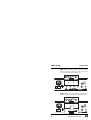
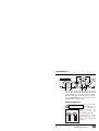
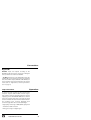
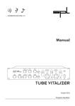
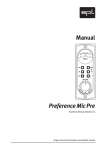
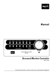
Manual
24/96 AD-DA Converter
Model 2053
Manual
24/96 AD-DA Converter 2053
Version 1.0 – 8/2000
The information in this document has been carefully
verified and is assumed to be correct. However Sound
Performance Lab (SPL) reserves the right to modify the
product described in this manual at any time. Changes
without notice. This document is the property of SPL
and may not be copied or reproduced in any manner,
in part or full without the authorization of SPL.
Limitations of Liability:
In no event will SPL be liable for any damages, including loss of data, lost profits, cost of cover or other
special, incidental, consequential or indirect damages
arising from the use of the unit, however caused and
on any theory of liability.This limitation will apply even
if SPL or an authorized dealer has been adviced of the
possibility of such damage.
Sound Performance Lab
P.O. Box 12 27
D- 41368 Niederkruechten, Germany
Phone +49 - 21 63 / 98 34-0
Fax +49 - 21 63 / 98 34-20
eMail: [email protected]
www.soundperformancelab.com
© 2000 SPL electronics GmbH. All Rights Reserved.
2
24/96 AD-DA Converter 2053
Contents
Security Advices ................................................................
4
Product Description .........................................................
4
Mounting
General Information .................................................
Steps 1 and 2 ..............................................................
Steps 3 and 4 ..............................................................
5
6
7
Connections ........................................................................
Analog XLR Outputs ................................................
Digital I/Os ..................................................................
8
8
9
Operation
Scope of Functions ................................................... 9
AD MODE Switch ...................................................... 10
ERROR-LEDs ............................................................... 10
External Synchronization ....................................... 11
Applications
Channel One: Using both converters ..................
Ch. One: Using both channels of the converter
24Bit/96 kHz Monitoring ........................................
Analog processing of a digital signal .................
Example 1: Processing a sampler’s signal ..........
Example 2: Recording on a DAT Recorder ..........
12
12
13
13
14
14
Specifications ..................................................................... 15
Block Diagram .................................................................... 16
Measurements ................................................................... 17
Warranty .............................................................................. 19
24/96 AD-DA Converter 2053
3
Security Advices
• Please consider referring the installation of the unit
operating the converter the safety information in the
corresponding operation instruction.
• Please carry out the self-installation only as described from page 5. In case of queries please contact an
expert.
Product Description
The SPL converter module 2053 combines separately
useable A/D and D/A converters, with a wordwidth up
to 24 Bits, and a Sample-rate of up to 96 kHz.
The D/A converter processes up to 24 Bits automatically, as well as sample-rates from 32Bit to 96 kHz and
is equipped with high-quality, balanced XLR outputs
(+ 12 dBu).
The A/D converter supports 16 and 24Bit formats
and works. The reduction from 24Bit to 16Bit is
processed with the Dithering-method: the "missing"
lower 8Bit is not cut off, but rather "included" in the 16
Bit format. This ensures that quietest passages are
preserved.
Internal Synchronization: The converter module
allows to choose 5 different clock sources via the AD
MODE switch.The internal sample rates (96 kHz/48 kHz
and 88.2 kHz/44.1 kHz) are Quartz-generated.
4
24/96 AD-DA Converter 2053
Product Description
External synchronization: For synchronization with
external sources, AES-data or Word-Clock signals can
be used as sync sources. Alternatively the A/D
converter can be synchronized to the data adjacent to
the D/A converter. For internal/external synchronization please refer to the chapter "Operation", from
page 11.
General Information
Mounting
The SPL converter module 2053 is exclusively offered
as an option for certain SPL units. We especially advise
electronically inexperienced users to contact an
expert in case of queries.
• In order to avoid static loads, please deactivate the
GND-Lift switch on the back of the unit that is to be
upgraded and touch its case.
• Now pull the power cord out of the socket on the
back of the unit operating the converter module.
Please also remove all other cable connections.
• Treat the converter carefully. Please make sure that
you only touch the front panel or the sides of the circuit board in order to avoid contact with parts on the
circuit board. Never force any parts when connecting
unit and converter module.
24/96 AD-DA Converter 2053
5
Mounting
Steps 1 and 2
Step 1: Please put the converter module as illustrated on the unit top and remove the screws of the
cover from the back of the upgrade unit.
Socket
Step 2: Please remove the mounting of the wiring on
the back of the cover (eventually cut off the silicon).
Socket
Connector
6
24/96 AD-DA Converter 2053
Mounting
Steps 3 and 4
Step 3: Connect the cable carefully, without turning,
to the socket of the converter. Guideways on socket
and plug exclude a wrong connection.
Sockel
Step 4:
Put the converter, as illustrated, without
lateral turning in the unit (circuit board above,
connection sockets on the head) and connect it with
the screws of the cover. The converter is now operational.
24/96 AD-DA Converter 2053
7
Connections
2
3
1
The converter module provides analog, balanced XLR
outputs (1), digital XLR I/Os (AES/EBU) (2) and digital
S/P-DIF I/Os (3). In case of using the S/P-DIF output as
a WC/AES SYNC input, the S/P-DIF output is no longer
available. Important: please never use AES- and S/PDIF digital inputs simultaneously!
Analog XLR Outputs
1
2
3
The unit operating
the module has to
be switched off
before
connecting
the
converter via the XLR
outputs with other units.
Wiring XLR Output
1 = GND, 2 = hot (+), 3 = cold (-)
Balanced
Unbalanced
The illustration to the left
demonstrates the correct
wiring
for
unbalanced
operation.
1=GND 2=hot (+) 3=cold (-)
8
24/96 AD-DA Converter 2053
Connections
Digital I/Os
AES/EBU: Inputs and outputs according to the
AES/EBU specification for the connection of all digital
units specified in accordance to AES/EBU.
S/P-DIF: Alternatively to the digital XLR-sockets, the
S/P-DIF I/Os can be used for the connection of digital
units. The S/P-DIF output (=WC/AES SYNC INPUT) can
also be used for external synchronization via external
clocks (refer to "Applications, external synchronization" on page 11).
Scope of Functions
Operation
In contrast to usual concepts, the SPL converter 2053
comprises separate A/D and D/A converter stages.
First of all the converter is determined for the optional
equipping of the SPL CHANNEL ONE (mono channel
strip). The possible applications generally described
concern all future SPL units which are determined for
the recording of the converter. Equipping both
converter stages offers two essential advantages:
• High-quality monitoring in 24Bit/96kHz quality with
simultaneous A/D conversion
• Analog processing of a digital signal
24/96 AD-DA Converter 2053
9
Operation
AD MODE Switch
The AD MODE switch is used to set the
desired bit mode and sample rate.The following list explains the respective switch
positions:
16 Bit Mode
E = AES
D = DA
C = WC
B = 48
A = 44,1
9 = 96
8 = 88,2
Ext. Synchronization to AES clock
Synchronization zum D/A converter
Ext. Synchronization to word clock
Int. Synchronization to 48 kHz
Int. Synchronization to 44,1 kHz
Int. Synchronization to 96 kHz
Int. Synchronization to 88,2 kHz
24 Bit Mode
0 = 88,2
1 = 96
2 = 44,1
3 = 48
4 = WC
5 = DA
6 = AES
Int. Synchronization to 88,2 kHz
Int. Synchronization to 96 kHz
Int. Synchronization to 44,1 kHz
Int. Synchronization to 48 kHz
Ext. Synchronization to word clock
Synchronization to D/A converter
Ext. Synchronization to AES clock
Error LEDs
The Error-LEDs indicate faulty audio signals at the S/PDIF input or faulty sync signals at the WC/AES SYNC
INPUT (=S/P-DIF output). In this case the respective
signal is muted.
10
24/96 AD-DA Converter 2053
Operation
External Synchronization
External Synchronization (Connection via W/C-AES
SYNC INPUT) is required when several signals must be
brought together within a chain of digital units, e.g.
when connecting several digital units at one console.
Since the sample frequencies are never exactly identical, not synchronized sample rates inevitably have
different timings - samples are ignored or read twice,
usually audible als cracking.
By supplying all signal sources with a common
frequency, all signals are synchronized and sample
faults are avoided.
The common frequency can either be transmitted
via unbalanced coaxial wiring using a BNC/CINCH
adapter as Word/House Clock or as AES data if
connected as shown in the graphic below. In both
cases the WC/AES SYNC INPUT is to be used.
1
1
2
2
3
AES XLR Connector
1 = GND, 2 = Signal,
3 = Signal to GND (3 to 1)
24/96 AD-DA Converter 2053
Cinch
1 = Sleeve
2 = Tip
11
Applications
CHANNEL ONE: Using both converters
Referring to the CHANNEL ONE, the separate use of
both converters can be for example the conversion of
digital signals independent from the A/D converter
and to reproduce them in best tonal quality on loudspeakers or headphones.
Example: High-quality conversion of a digital console's output signal.
Another application is the high-end conversion of
digital signals for the further analog processing (refer
to "Operation, analog processing of a digital signal",
page 13).
CHANNEL ONE: Using both channels of
the converter
The CHANNEL ONE is a mono unit. Consequently only
one channel of the A/D converter can be used with it.
Since A/D converters usually are designed as stereo
units with two channels, it is possible to convert a
second mono signal via the A/D INPUT 2 on the
CHANNEL ONE. If this socket is not in use, the A/DConverter routes the mono signal of the CHANNEL
ONE to both channels.
Example: During a voice recording with the
CHANNEL ONE, a guitar signal can be converted at the
same time.
12
24/96 AD-DA Converter 2053
Applications
Monitoring in 24Bit/96kHz
A high standard of monitoring is necessary for
judging the recording quality. Therefore all digital
signals have to be converted into analog signals to
allow reproduction on loudspeakers or headphones.
The A/D converter stage is equipped with highquality components and ensures excellent tonal
results. We recommend to use the SPL converter
rather than the converters found in DAT recorders,
sound cards or digital consoles.
Analog processing of a digital signal
Together with the converter module, the inputs of the
CHANNEL ONE can also be used for digital signals to
have access to the entire processing bandwidth including the tube pre-amplifier.
Please consider the following instructions: the sockets
INSTR. IN (front) and LINE (back) need not be occupied. The MIC/LINE switch has to be set to LINE. The
converter signal is now routed to the preamplifying
stage of the CHANNEL ONE.
The LINE socket is a switch socket - a signal connected
to the LINE socket takes priority, otherwise the
converter signal will be connected through.
24/96 AD-DA Converter 2053
13
Applications
Example 1: Processing a sampler's signal
Connect the output of the sampler via AES/EBU or
S/P-DIF interface with the input of the converter. The
adjustment described in the section above now
allows to process the sampler's signal. If the processed
signal is to be returned digitally converted to the
sampler, the A/D converter has to be synchronized to
the D/A converter (= external synchronization; the
D/A converter is the source clock for the A/D
converter). In this case, please set the AD MODE switch
on the converter module to position "5" (24 Bit) or "D"
(16 Bit).
Example 2: Recording on a DAT recorder
If the processed signal is to be recorded on a DAT
recorder, the best Bit-format of the DAT-recorder must
be chosen on the AD MODE switch (16 or 24 Bit), while
the internal synchronization should be adapted to the
desired sample rate. For 16 Bit operation choose one
of the switch positions B, A, 9 or 8, for 24 Bit 0, 1, 2, or 3.
Unless a House-Clock controls all digital units: in this
case please set the AD MODE switch to position C for
16 Bit or 4 for 24Bit (compare chapter "Operation,
internal and external synchronization", page 11).
14
24/96 AD-DA Converter 2053
Specifications
A/D Converter
Wordwidth ................................... 24 Bit
Reduced Wordwidth ................ 16 Bit
Dither ............................................ triangular
Internal sample rates .............. 44.1/48/88.2/96 kHz
External sample rates .............. 32-96 kHz
Sync sources .............................. AES 11 or word clock
THD+N @-1 dBFs, 1 kHz ........... <-101 dB
Dynamic range (A) ................... 110 dB
D/A Converter
Wordwidth ................................... 24Bit
Sample rates .............................. 32-96 kHz
THD+N (@-1 dBFs, 1 kHz) ........ <-90 dB
Dynamic range (A, Q 96 kHz) ... 105 dB
24/96 AD-DA Converter 2053
15
Block Diagram
16
24/96 AD-DA Converter 2053
Measurements
D/A: THD&N above input level
D/A: THD&N @ 1 kHz FFT
24/96 AD-DA Converter 2053
17
Measurements
A/D: THD&N above input level
A/D: THD&N @ 1 kHz FFT
18
24/96 AD-DA Converter 2053
Warranty
SPL electronics GmbH (hereafter called SPL) products are warranted
only in the country where purchased, through the authorized SPL distributor in that country, against defects in material or workmanship. The
specific period of this limited warranty shall be that which is described
to the original retail purchaser by the authorized SPL dealer or distributor at the time of purchase.
SPL does not, however, warrant its products against any and all defects:
1) arising out of materials or workmanship not provided or furnished
by SPL, or 2) resulting from abnormal use of the product or use in violation of instructions, or 3) in products repaired or serviced by other than
authorized SPL repair facilities, or 4) in products with removed or
defaced serial numbers, or 5) in components or parts or products
expressly warranted by another manufacturer.
SPL agrees, through the applicable authorized distributor, to repair or
replace defects covered by this limited warranty with parts or products
of original or improved design, at its option in each respect, if the defective product is shipped prior to the end of the warranty period to the
designated authorized SPL warranty repair facility in the country where
purchased, or to the SPL factory in Germany, in the original packaging or
a replacement supplied by SPL, with all transportation costs and full
insurance paid each way by the purchaser or owner.
All remedies and the measure of damages are limited to the above
services. It is possible that economic loss or injury to person or property
may result from the failure of the product; however, even if SPL has been
advised of this possibility, this limited warranty does not cover any such
consequential or incidental damages. Some states or countries do not
allow the limitations or exclusion of incidental or consequential
damages, so the above limitation may not apply to you.
Any and all warranties, express or implied, arising by law, course of
dealing, course of performance, usage of trade, or otherwise, including
but not limited to implied warranties of merchantability and fitness for
particular, are limited to a period of 1 (one) year from either the date of
manufacture. Some states or countries do not allow limitations on how
long an implied warranty lasts, so the above limitations may not apply to
you.
This limited warranty gives you specific legal rights, and you may also
have other rights which vary from state to state, country to country.
SPL electronics GmbH, 41372 Niederkruechten, Germany
24/96 AD-DA Converter 2053
19
Sound Performance Lab
Sohlweg 55
D-41372 Niederkruechten
Germany
Tel. +49 • 2163 • 9834-0, Fax -20
[email protected]
www.soundperformancelab.com
24/96 AD-DA Converter, Model 2053