1
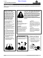
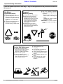
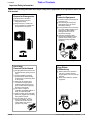
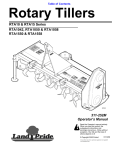
Table of Contents
Powered Ditchers
DT55 & DTM55
25751
324-053M
Operator’s Manual
!
Read the Operator’s manual entirely. When
you see this symbol, the subsequent
instructions and warnings are serious - follow
without exception. Your life and the lives of
others depend on it!
© Copyright 2008 Printed
3/17/08
Cover photo may show optional equipment
not supplied with standard unit.
Table of Contents
Table of Contents
Important Safety Information . . . . . . . . . . .1
Section 3: Adjustments . . . . . . . . . . . . . .14
Safety at All Times . . . . . . . . . . . . . . . . . . . . . . . . . 1
Look For The Safety Alert Symbol . . . . . . . . . . . . . 1
Safety Labels . . . . . . . . . . . . . . . . . . . . . . . . . . . . . 4
Drive Chain Adjustment . . . . . . . . . . . . . . . . . . . . 14
Gauge Wheel . . . . . . . . . . . . . . . . . . . . . . . . . . . . 14
Manual Chute Adjustment . . . . . . . . . . . . . . . . . . 14
Hydraulic Chute Adjustment . . . . . . . . . . . . . . . . . 15
Ripper Depth Adjustment . . . . . . . . . . . . . . . . . . . 15
Introduction . . . . . . . . . . . . . . . . . . . . . . . .7
Application . . . . . . . . . . . . . . . . . . . . . . . . . . . . . . . 7
Using This Manual . . . . . . . . . . . . . . . . . . . . . . . . . 7
Terminology . . . . . . . . . . . . . . . . . . . . . . . . . . . 7
Definitions . . . . . . . . . . . . . . . . . . . . . . . . . . . . . 7
Owner Assistance . . . . . . . . . . . . . . . . . . . . . . . . . 7
Serial Number Plate . . . . . . . . . . . . . . . . . . . . . 7
Further Assistance . . . . . . . . . . . . . . . . . . . . . . 7
Section 1: Assembly and Set-Up . . . . . . . .8
Tractor Requirements . . . . . . . . . . . . . . . . . . . . . . 8
Tractor Hook-Up . . . . . . . . . . . . . . . . . . . . . . . . . . 8
Driveline Set-Up . . . . . . . . . . . . . . . . . . . . . . . . . . . 8
Checking Driveline Minimum Length . . . . . . . . . 8
Driveline Maximum Allowable Length . . . . . . . . 9
Manual Chute Option Assembly . . . . . . . . . . . . . . 10
Hydraulic Chute Option Assembly . . . . . . . . . . . . 10
Ripper Option Assembly . . . . . . . . . . . . . . . . . . . 11
Skid Shoe Option Assembly . . . . . . . . . . . . . . . . 11
Gauge Wheel Option Assembly . . . . . . . . . . . . . . 11
Section 2: Operating Instructions . . . . . .12
Transporting . . . . . . . . . . . . . . . . . . . . . . . . . . . . 12
Operating Checklist . . . . . . . . . . . . . . . . . . . . . . . 12
Operating Instructions . . . . . . . . . . . . . . . . . . . . . 12
General Operating Instructions . . . . . . . . . . . . . . 12
Section 4: Maintenance & Lubrication . .16
Maintenance . . . . . . . . . . . . . . . . . . . . . . . . . . . . 16
Storage . . . . . . . . . . . . . . . . . . . . . . . . . . . . . . . . 16
Drive Chain Maintenance . . . . . . . . . . . . . . . . . . . 16
Drive Sprocket and Drive Chain Replacement . . . 17
Lubrication . . . . . . . . . . . . . . . . . . . . . . . . . . . . . . 18
Input Shaft Bearing . . . . . . . . . . . . . . . . . . . . . 18
Output Shaft Bearings . . . . . . . . . . . . . . . . . . . 18
Drive Chain . . . . . . . . . . . . . . . . . . . . . . . . . . . 18
Driveline Shafts . . . . . . . . . . . . . . . . . . . . . . . . 19
Driveline U-Joints (Zerks Both Ends) . . . . . . . . 19
Gauge Wheel Option Bearing . . . . . . . . . . . . . 19
Section 5: Specifications & Capacities . .20
Section 6: Features & Benefits . . . . . . . .21
Section 7: Troubleshooting . . . . . . . . . . .22
Section 8: Appendix . . . . . . . . . . . . . . . . .23
Torque Values Chart For Common Bolt Size . . . . 23
Notes . . . . . . . . . . . . . . . . . . . . . . . . . . . . . . . . . . 24
Warranty . . . . . . . . . . . . . . . . . . . . . . . . . . . . . . . 25
© Copyright 2008 All rights Reserved
Land Pride provides this publication “as is” without warranty of any kind, either expressed or implied. While every precaution has been taken in the preparation of this manual, Land
Pride assumes no responsibility for errors or omissions. Neither is any liability assumed for damages resulting from the use of the information contained herein. Land Pride reserves
the right to revise and improve its products as it sees fit. This publication describes the state of this product at the time of its publication, and may not reflect the product in the future.
Land Pride is a registered trademark.
All other brands and product names are trademarks or registered trademarks of their respective holders.
Printed in the United States of America.
DT55 & DTM55 Powered Ditchers 324-053M
3/17/08
Land Pride
▲
Table of Contents
Important Safety Information
Important Safety Information
These are common practices that may or may not be applicable to the products described in
this manual.
Safety at All Times
Look For The Safety Alert Symbol
Thoroughly read and understand
the instructions given in this
manual before operation. Refer to
the “Safety Label” section, read
all instructions noted on them.
Do not allow anyone to operate
this equipment who has not fully
read and comprehended this
manual and who has not been
properly trained in the safe
operation of the equipment.
The SAFETY ALERT SYMBOL indicates there is a
potential hazard to personal safety involved and extra
safety precaution must be taken. When you see this
symbol, be alert and carefully read the message that
follows it. In addition to design and configuration of
equipment, hazard control and accident prevention
are dependent upon the awareness, concern,
prudence and proper training of personnel involved in
the operation, transport, maintenance and storage of
equipment.
▲ Operator should be familiar with
all functions of the unit.
▲ Operate implement from the
driver’s seat only.
▲ Make sure all guards and shields
are in place and secured before
operating the implement.
▲ Do not leave tractor or implement
unattended with engine running.
▲ Dismounting from a moving
tractor could cause serious injury
or death.
▲ Do not stand between the tractor
and implement during hitching.
▲ Keep hands, feet, and clothing
away from power-driven parts.
▲ Wear snug fitting clothing to avoid
entanglement with moving parts.
▲ Watch out for wires, trees, etc.,
when raising implement. Make
sure all persons are clear of
working area.
▲ Turning tractor too tight may
cause implement to ride up on
wheels. This could result in injury
or equipment damage.
!
Be Aware of
Signal Words
A Signal word designates a degree or
level of hazard seriousness. The
signal words are:
! DANGER
Indicates an imminently hazardous
situation which, if not avoided, will
result in death or serious injury. This
signal word is limited to the most
extreme situations, typically for
machine components that, for
functional purposes, cannot be
guarded.
! WARNING
Indicates a potentially hazardous
situation which, if not avoided, could
result in death or serious injury, and
includes hazards that are exposed
when guards are removed. It may also
be used to alert against unsafe
practices.
! CAUTION
Indicates a potentially hazardous
situation which, if not avoided, may
result in minor or moderate injury. It
may also be used to alert against
unsafe practices.
For Your Protection
Shutdown and Storage
▲ Thoroughly read and understand
the “Safety Label” section, read all
instructions noted on them.
▲ Lower machine to ground, put
tractor in park, turn off engine, and
remove the key.
▲ Detach and store implements in a
area where children normally do
not play. Secure implement by
using blocks and supports.
OFF
REMO
VE
3/17/08
DT55 & DTM55 Powered Ditchers 324-053M
1
Table of Contents
Land Pride
Important Safety Information
These are common practices that may or may not be applicable to the products described in
this manual.
Use Safety
Lights and Devices
Transport
Machinery Safely
▲ Slow moving tractors, selfpropelled equipment, and towed
implements can create a hazard
when driven on public roads. They
are difficult to see, especially at
night.
▲ Flashing warning lights and turn
signals are recommended
whenever driving on public roads.
▲ Comply with state and local laws.
▲ Maximum transport speed for
implement is 20 mph. DO NOT
EXCEED. Never travel at a speed
which does not allow adequate
control of steering and stopping.
Some rough terrain require a
slower speed.
▲ Sudden braking can cause a
towed load to swerve and upset.
Reduce speed if towed load is not
equipped with brakes.
Practice Safe Maintenance
▲ Understand procedure before
doing work. Use proper tools and
equipment, refer to Operator’s
Manual for additional information.
▲ Work in a clean dry area.
▲ Lower the implement to the
ground, put tractor in park, turn off
engine, and remove key before
performing maintenance.
2
DT55 & DTM55 Powered Ditchers 324-053M
▲ Use the following maximum
speed - tow load weight ratios as
a guideline:
20 mph when weight is less
than or equal to the weight of
tractor.
10 mph when weight is double
the weight of tractor.
IMPORTANT: Do not tow a load that
is more than double the weight of
tractor.
▲ Allow implement to cool
completely.
▲ Do not grease or oil implement
while it is in operation.
▲ Inspect all parts. Make sure parts
are in good condition & installed
properly.
▲ Remove buildup of grease, oil or
debris.
▲ Remove all tools and unused
parts from implement before
operation.
3/17/08
Table of Contents
Land Pride
Important Safety Information
These are common practices that may or may not be applicable to the products described in
this manual.
Prepare for Emergencies
▲ Be prepared if a fire starts.
▲ Keep a first aid kit and fire
extinguisher handy.
▲ Keep emergency numbers for
doctor, ambulance, hospital and
fire department near phone.
Wear
Protective Equipment
▲ Protective clothing and equipment
should be worn.
▲ Wear clothing and equipment
appropriate for the job. Avoid
loose fitting clothing.
▲ Prolonged exposure to loud noise
can cause hearing impairment or
hearing loss. Wear suitable
hearing protection such as
earmuffs or earplugs.
▲ Operating equipment safely
requires the full attention of the
operator. Avoid wearing radio
headphones while operating
machinery.
911
Avoid High
Pressure Fluids Hazard
▲ Escaping fluid under pressure can
penetrate the skin causing serious
injury.
▲ Avoid the hazard by relieving
pressure before disconnecting
hydraulic lines or performing work
on the system.
▲ Make sure all hydraulic fluid
connections are tight and all
hydraulic hoses and lines are in
good condition before aqpplying
pressure to the system.
▲ Use a piece of paper or
cardboard, NOT BODY PARTS, to
check for suspected leaks.
▲ Wear protective gloves and safety
glasses or goggles when working
with hydraulic systems.
▲ If an accident occurs, see a
doctor immediately. Any fluid
injected into the skin must be
treated within a few hours or
gangrene may result.
3/17/08
Keep Riders
Off Machinery
▲ Riders obstruct the operator’s
view, they could be struck by
foreign objects or thrown from the
machine.
▲ Never allow children to operate
equipment.
DT55 & DTM55 Powered Ditchers 324-053M
3
Table of Contents
Land Pride
Important Safety Information
Safety Labels
Your Ditcher comes equipped with all safety labels in place.
They were designed to help you safely operate your implement.
Read and follow their directions.
1. Keep all safety labels clean and legible.
2. Replace all damaged or missing labels. To order new
labels go to your nearest Land Pride dealer or visit our
dealer locator at landpride.com.
3. Some new equipment installed during repair requires
safety labels to be affixed to the replaced component as
4.
specified by Land Pride. When ordering new components
make sure the correct safety labels are included in the
request.
Refer to this section for proper label placement.
To install new labels:
a. Clean the area the label is to be placed.
b. Spray soapy water on the surface where the label is to
be placed.
c. Peel backing from label. Press firmly onto the surface.
d. Squeeze out air bubbles with the edge of a credit card.
818-130C (DT55)
25751
Caution: 540 RPM
818-240C (DTM55)
Caution: 1000 RPM
ROTATING DRIVELINE
KEEP AWAY!
25758
818-552C
Caution: Rotating Driveline
838-111C
25758
Danger: Moving Parts
4
DT55 & DTM55 Powered Ditchers 324-053M
3/17/08
Land Pride
Table of Contents
Important Safety Information
25751
818-719C
Caution: General Instructions
25758
838-295C
Danger: Rotating Blade
838-287C
25751
Danger: Thrown Object
838-381C
Danger
25758
3/17/08
DT55 & DTM55 Powered Ditchers 324-053M
5
Table of Contents
Land Pride
Important Safety Information
818-229C (Chute Option)
25751
Amber Reflector
818-230C (Chute Option)
25758
Red Reflector
838-112C
(Chute Option
Both Sides)
25751
Danger: Pinching
838-094C
(Hydraulic Chute Option)
25758
6
Warning: Hydraulic Pressure
DT55 & DTM55 Powered Ditchers 324-053M
3/17/08
Land Pride
Table of Contents
Introduction
Introduction
Land Pride welcomes you to the growing family of new
product owners.
This Ditcher has been designed with care and built by
skilled workers using quality materials. Proper assembly,
maintenance, and safe operating practices will help you
get years of satisfactory use from the Powered Ditcher.
Application
The DT55 Powered Ditcher is a versatile tool to use in
many water control applications. Cleaning water ditches
along roadsides or in farm fields to drain standing water
away from crops, the DT55 makes it simple. The 20"
impeller leaves a clean and sculptured trough to keep
water flowing freely from unwanted areas. With the
optional Material Control Chute in place, dirt can be
placed just next to the machine, or thrown many feet
away to reshape terraces. An optional ripper, gauge
wheel and skid shoe can be attached to aid in reshaping
terraces and grader ditches. See “Features and
Benefits”, “Section 6” for additional information.
The parts on your Powered Ditcher have been specially
designed and should only be replaced with genuine Land
Pride parts. Therefore, should your Ditcher require
replacement parts go to your Land Pride Dealer.
Serial Number Plate
For prompt service always use the serial number and
model number when ordering parts from your Land Pride
dealer. Be sure to include your serial and model numbers
in correspondence also. Refer to Figure 1 for the location
of your serial number plate.
Using This Manual
• This Operator’s Manual is designed to help familiarize
•
•
you with safety, assembly, operation, adjustments,
troubleshooting, and maintenance. Read this manual
and follow the recommendations to help ensure safe
and efficient operation.
The information contained within this manual was
current at the time of printing. Some parts may change
slightly to assure you of the best performance.
To order a new Operator’s or Parts Manual contact
your authorized dealer. Manuals can also be
downloaded, free-of-charge from our website at
www.landpride.com or printed from the Land Pride
Service & Support Center by your dealer.
Terminology
“Right” or “Left” as used in this manual is determined by
facing the direction the machine will operate while in use
unless otherwise stated.
Definitions
NOTE: A special point of information that the
operator must be aware of before continuing.
IMPORTANT: A special point of information related
to its preceding topic. Land Pride’s intention is that
this information should be read and noted before
continuing.
Owner Assistance
The Warranty Registration card should be filled out by
the dealer at the time of purchase. This information is
necessary to provide you with quality customer service.
If customer service or repair parts are required contact a
Land Pride dealer. A dealer has trained personnel, repair
parts and equipment needed to service the Powered
Ditcher.
3/17/08
19363
Serial Number Plate Location
Figure 1
Further Assistance
Your dealer wants you to be satisfied with your new
Powered Ditcher. If for any reason you do not
understand any part of this manual or are not satisfied
with the service received, the following actions are
suggested:
1. Discuss the matter with your dealership service
manager making sure he is aware of any problems
you may have and that he has had the opportunity to
assist you.
2. If you are still not satisfied, seek out the owner or
general manager of the dealership, explain the
problem and request assistance.
3. For further assistance write to:
Land Pride Service Department
1525 East North Street
P.O. Box 5060
Salina, Ks. 67402-5060
E-mail address
[email protected]
DT55 & DTM55 Powered Ditchers 324-053M
7
Table of Contents
Land Pride
Section 1: Assembly and Set-Up
Section 1: Assembly and Set-Up
Tractor Requirements
Driveline Set-Up
This Powered Ditcher is designed with a Category 2 and
3, 3-point hitch. The maximum horsepower rating for the
tractor is 120 HP depending on lift capacity and field
conditions. Front tractor weights and/or ballast to tires
may be required to offset weight of unit. Consult your
tractor manual for details.
If the Ditcher is to be used on more than one tractor, an
additional driveline may be required - especially if a quick
hitch is used.
!
CAUTION
Your Ditcher must be mounted only on a tractor equipped with
a Category 2 or 3 hitch. Failure to do so may result in serious
injury.
Tractor Hook-Up
!
DANGER
Tractor hook-up to equipment is dangerous and can result in
serious injury or death. Do not allow anyone to stand between
the Powered Ditcher and tractor during hook-up operations.
Do not operate the hydraulic 3-point lift controls while
someone is directly behind the tractor or near the implement.
!
CAUTION
!
WARNING
Damaged drivelines can cause serious injury or death.
!
CAUTION
Tractor PTO shield and all Ditcher guards must be in place at
all times during operation!
IMPORTANT: Some tractors are equipped with
multispeed PTO ranges. Be certain your tractor ‘s
PTO is set for the correct PTO speed.
DANGER
Hydraulic fluid under pressure can penetrate skin. Wear
protective gloves and safety glasses or goggles when working
with hydraulic systems. Use a piece of cardboard or wood
rather than hands when searching for hydraulic leaks. If
hydraulic fluid is injected into the skin, it must be treated by a
doctor within a few hours or gangrene may result.
1. Slowly back tractor up to the Powered Ditcher while
using the tractor’s 3-point hydraulic control to align
the lower hitch link holes with the clevis lug holes on
the implement.
2. Engage tractor park brake, shut tractor engine off
and remove key before dismounting from tractor.
3. With tractor’s lower hitch arms aligned and
positioned in the clevises, attach the lower arms to
the clevises with hitch pins and secure with linch
pins.
4. Connect top center link to the upper pivot hitch using
customer supplied clevis pin and linch pin.
5. Ensure that the lower hitch arms are blocked to
prevent excessive side movement.
6. Return to the tractor and slowly operate the 3-point
controls up and down to check for clearance between
the implement and tractor. Move or remove the
drawbar if it interferes with the Powered Ditcher.
7. Manually adjust one of the two lower lift arms up or
down to level the Powered Ditcher from left to right.
Manually adjust the length of the top-link to level the
Powered Ditcher from front to rear.
8
!
Do not use a PTO adaptor with a quick hitch. A PTO adapter
will increase the strain on the tractor’s PTO shaft and can
damage the PTO shaft and tiller driveline.
DT55 & DTM55 Powered Ditchers 324-053M
IMPORTANT: Avoid premature driveline
breakdown. A driveline that is operating must not
exceed an angle of 25 degrees up or down while
operating the 3-point lift. See Figure 1-1 below.
24872
Maximum Allowable Driveline Movement
Figure 1-1
Checking Driveline Minimum Length
IMPORTANT: Always check driveline minimum
length and maximum allowable length during initial
setup and when connecting to a different tractor.
More than one driveline may be required to fit all
applications.
3/17/08
Table of Contents
Land Pride
Section 1: Assembly and Set-Up
IMPORTANT: It is necessary to align the tractor’s
PTO shaft level with the Powered Ditcher’s drive
shaft when checking driveline minimum length. Too
long a driveline can damage tractor, driveline and
Powered Ditcher.
1. Start tractor and slowly engage tractor’s hydraulic
3-point lever to move the lower arms up or down until
the driveline shaft is approximately level. Securely
block the Powered Ditcher in this position.
Refer to Figure 1-2 on page 9:
2. Place tractor gear selector in park, shut tractor engine
off, set park brake and remove switch key.
IMPORTANT: The inner shield half attaches to the
Ditcher.
3. Attach driveline to Powered Ditcher and tractor as
follows:
a. Slide inner universal joint of driveline over the
Powered Ditcher’s drive shaft and secure with
locking collar.
b. Slide outer universal joint driveline over the
tractor's PTO shaft and secure with locking collar.
c. Skip to "Driveline Maximum Allowable Length" if
driveline fits.
gearbox shaft. Pull on each driveline section to be
sure universal joints are secured.
d. Hold driveline sections parallel to each other to
determine if they are too long. The inner and outer
shields on each section should end approximately
1" short of reaching the universal joint shield on
the adjacent section (see “B” dimension). If they
are too long, measure 1" (“B” dimension) back
from the universal joint shield and make a mark at
this location on the inner and outer shields.
e. Cut off inner shield at mark (“X” dimension). Cut
same amount off inner shaft (“X1” dimension).
Repeat cut off procedure (“Y” & “Y1” dimensions)
to cut outer driveline half.
f. Remove all burrs and cuttings.
Driveline Maximum Allowable Length
Be sure to check driveline minimum length before
checking driveline maximum allowable length.
Refer to Figure 1-3:
Driveline maximum allowable length, when fully
extended, must have a minimum overlap of profile tubes
by not less than 1/2 the free length with both inner and
outer profile tubes being of equal length.
24804
Outer Shielding has been removed for clarity.
Driveline Maximum Length
Figure 1-3
23758
Driveline Shortening
Figure 1-2
4. The driveline will require shortening if it is too long to
fit between the tractor and Powered Ditcher. Shorten
driveline as follows:
a. Make sure the Powered Ditcher and tractor PTO
shafts are level with each other and the
implement is securely supported at this height
with support blocks.
b. Pull driveline profiles apart into two sections as
shown in Figure 1-2.
c. Attach outer driveline universal joint to tractor
PTO shaft and inner driveline universal joint to
3/17/08
1. Pull inner and outer profiles apart. Measure and
record free length of both profiles. They should be
the same.
2. With driveline profiles pulled apart, apply
multi-purpose grease to the inside of the outer profile
and reassemble the two profiles.
3. Move driveline halves together until profile tubes
overlap by 1/2 the free length. Measure and record
maximum allowable length shown in Figure 1-3.
4. Attach inner driveline yoke to drive shaft and outer
driveline yoke to tractor's PTO shaft.
5. The driveline should now be moved back and forth to
insure that both ends are secured. Reattach any end
that is loose.
DT55 & DTM55 Powered Ditchers 324-053M
9
Table of Contents
Land Pride
Section 1: Assembly and Set-Up
IMPORTANT: A small chain is supplied with the
driveline. This chain must be attached to the inner
driveline shield and to the Powered Ditcher to
restrict shield rotation.
6. Hook driveline safety chain in the hole in the inner
driveline guard. Attach the other end to the Powered
Ditcher’s main frame.
7. Start tractor and raise Powered Ditcher just enough
to remove support blocks.
8. Slowly engage tractor’s 3-point controls to lower
Powered Ditcher. Check for sufficient drawbar
clearance. Move drawbar ahead, aside or remove if
required.
9. Raise and lower implement to find the maximum
possible extended driveline length. Check to make
certain that the driveline has not extended beyond
the maximum allowable length recorded in step 3 on
page 9.
Hydraulic Chute Option Assembly
Refer to Figure 1-5:
1. Assemble Chute (#1) to the main frame with hinge
pin (#2) and cotter pins (#3). Bend one leg of each
cotter pin to keep cotter pin from falling out.
2. Attach hydraulic cylinder to the chute and frame lugs
as shown with clevis pins (#4). Secure clevis pins
with hair pin cotters.
3. Route hydraulic hoses through hose guide (#5) as
shown.
Manual Chute Option Assembly
Refer to Figure 1-4:
1. Assemble Chute (#1) to the main frame with hinge
pin (#3) and cotter pins (#4). Bend one leg of each
cotter pin to keep cotter pin from falling out.
2. Attach ratchet jack (#5) to the chute and frame lugs
as shown with clevis pins provided. Secure clevis
pins with hair pin cotters.
20522
Hydraulic Chute Option Assembly
Figure 1-5
20529
Manual Chute Option Assembly
Figure 1-4
10
DT55 & DTM55 Powered Ditchers 324-053M
3/17/08
Table of Contents
Land Pride
Section 1: Assembly and Set-Up
Ripper Option Assembly
Refer to Figure 1-6:
1. Assemble ripper Assembly (#1) to the main frame
with four 3/4” u-bolts (#2), lock washers (#3) and
3/4” nuts (#4). Tighten nuts to 170 ft-lbs. of torque.
25754
Skid Shoe Option Assembly
Figure 1-7
20520
Ripper Option Assembly
Figure 1-6
Skid Shoe Option Assembly
Refer to Figure 1-7:
1. Attach Skid Shoe (#1) to the main frame with
3/8”-16 x 1 1/4” GR5 round head square neck
bolt s (#2) and lock nuts (#3). Draw lock nuts up
snug, do not tighten.
2. Attach one end of turnbuckle (#5) to the main frame
lug with clevis pin (#6) and cotter pin (#4).
3. Attach other end of turnbuckle (#5) to the lug on the
skid shoe (#1) lug with clevis pin (#6) and cotter
pin (#4).
4. Bend one leg of each cotter pin to keep cotter pin
from falling out.
Gauge Wheel Option Assembly
Refer to Figure 1-8:
1. Assemble Gauge Wheel Assembly (#1) with hitch
pin (#2) and hair pin (#3).
20519
Gauge Wheel Option Assembly
Figure 1-8
3/17/08
DT55 & DTM55 Powered Ditchers 324-053M
11
Table of Contents
Land Pride
Section 2: Operating Instructions
Section 2: Operating Instructions
Transporting
IMPORTANT: ALWAYS disengage PTO before
raising the Powered Ditcher to transport position.
1. When raising the Powered Ditcher to the transport
position, be sure that the powershaft does not
contact tractor or implement.
2. Be sure to reduce tractor ground speed when
turning. Leave enough clearance so the Powered
Ditcher does not contact obstacles such as
buildings, trees or fences.
3. Select a safe ground travel speed when transporting
from one area to another. When traveling on
roadways, transport in such a way that faster moving
vehicles may pass you safely.
4. When traveling over rough or hilly terrain, shift tractor
to a lower gear.
!
CAUTION
When traveling on public roads, whether at night or during the
day, use accessory lights and devices for adequate warning to
operators of other vehicles. Comply with all federal, state, and
local laws.
Operating Checklist
Check
Reference
Check chain tension. Refer to “Drive
Chain Adjustment”.
Section 3
page 14
Check oil level in chaincase. Refer to
“Lubrication”.
Section 4
page 18
Check that all plugs have been replaced
properly in the chaincase.
Section 4
page 18
Check that all bolts and nuts are tight.
Operator’s
Manual
Be certain all guards and shields are in place
and secure.
Operator’s
Manual
Grease driveline shaft and all other grease
fittings. Refer to “Lubrication”.
Section 4
page 18
Check air pressure in gauge wheel tire. Refer
to Tire Inflation Chart for tire pressure.
Section 8
page 23
Operating Instructions
1. Operate with 540 rpm PTO tractor on the DT55 and
1000 rpm PTO on the DTM55.
2. Engage PTO at approximately 200 RPM and slowly
increase to proper PTO RPM.
3. Ditching should not be done in wet conditions as soil
will stick to the blades and reduce the digging ability
of the Ditcher.
4. DO NOT make sharp turns or attempt to back up
while Ditcher is in the ground.
12
DT55 & DTM55 Powered Ditchers 324-053M
5. DO NOT engage PTO with machine in the fully raised
position.
6. DO NOT drop 3 point hitch. Lower the Powered
Ditcher slowly to the ground.
7. Ground speed should be between 3 and 5 mph for
normal conditions. Under extreme rocky conditions
ground speed may have to be reduced for
satisfactory performance. In general, the slower the
ground speed the better job.
8. Proper operating depth and ground speed are
interrelated and performance of the Powered Ditcher
will improve with operator experience.
9. Periodically check for foreign objects wrapped
around the blades and remove them after
disengaging PTO, turning off tractor, and removing
ignition key.
General Operating Instructions
Now that you have familiarized yourself with the
Operator’s Manual, completed the Operator’s Checklist
and properly attached your Powered Ditcher to your
tractor, you are almost ready to begin using your Land
Pride 55 Series Powered Ditcher.
It is now time to do a running operational safety check. If
at any time during this safety check if you detect a
malfunction in either the Powered Ditcher or tractor, shut
tractor off immediately, remove switch key, and make
necessary repairs or adjustments before continuing on.
Make sure the tractor’s park brake is engaged, the
tractor’s PTO is disengaged, the Powered Ditcher is
slightly off of the ground and the power shaft is not in a
bind. Start the tractor and then back the tractor throttle off
until the engine is at low idle. With the tractor running at
an idle speed, make sure if equiped, that the optional
hydraulically controlled material deflector chute is
operating properly for on the go adjustment with the
tractor’s hydraulic controls. This is also the time to make
sure that the rear hydraulic control arms will lower the
Powered Ditcher from transport to working position and
back without putting the power shaft into a bind. Again,
lift the Powered Ditcher slightly off of the ground and
raise the engine rpm slightly. Engage the PTO drive and
check to make sure everything is running smoothly. If
not, safely shut the tractor down and make the necessary
corrections. If everything is in proper working condition,
you are ready to move to the work site.
You should inspect the area where you intend to work
making sure that there are no obvious debris, large
rocks, or other materials that are in your working path.
You will also want to make sure that there are no people,
animals, pets, valuable property and/or equipment in the
immediate vicinity that could be harmed by flying rocks,
dirt, or debris once you engage the Powered Ditcher.
3/17/08
Land Pride
Table of Contents
Section 2: Operating Instructions
If your unit has an optional depth controlling skid shoe
and if you have not already set it to the desired depth,
you should set the tractor’s park brake, shut tractor
engine off, remove switch key and then make that
setting.
You are now ready to begin operation. Make sure the unit
is lifted just barely off of the ground, raise the tractor
engine rpm slightly above idle and engage the PTO. The
best ditching performance is usually achieved at forward
speeds of approximately 3 to 5 mph, so make the proper
gear selection and then raise engine rpm to full PTO
speed. Begin forward motion while gently lowering the
Powered Ditcher into working position. You will
immediately begin to see a generous stream of dirt being
rapidly ejected off to the left side.
If you are not using a deflector shield, the dirt will usually
be ejected outward and will spread evenly over the
ground 20’ to 50’ out. If you are using a deflector shield to
form a burm or terrace, now is the time to make sure your
chute is correctly adjusted to achieve the desired results.
After you have traveled approximately 50’, it is a good
idea to lift the Powered Ditcher out of working position or
soil contact, safely shut your equipment down, and go
back to inspect the results. Then make required
adjustments before continuing on.
If your ground conditions are extremely hard, you may
find it necessary to employ an optional ripper
attachment. If your ground conditions are too wet, you
shouldn’t run at all until drier conditions prevail.
Remember to look back often. With a little practice you
will gain the required experience you need to help you
achieve the desired results you expect from your
Land Pride 55 Series Powered Ditcher.
When you are done ditching, need to take a break, or just
need to make a few adjustments to the Powered Ditcher,
always remember to do the following:
• Raise the Powered Ditcher up and out of soil contact
• Reduce the tractor’s engine rpm
• Disengage the PTO
• Stop on level ground
• Set the park brake
• Turn off the engine
• Remove the key
See “Features and Benefits” section or “Product
Specifications” for additional information and
performance enhancing options.
3/17/08
DT55 & DTM55 Powered Ditchers 324-053M
13
Table of Contents
Land Pride
Section 3: Adjustments
Section 3: Adjustments
!
Gauge Wheel
CAUTION
BEFORE any adjustments are performed, lower the Ditcher to
the ground slowly, stop tractor engine and remove switch key.
DO NOT attempt to make adjustments while tractor is
running.
NOTE: For corrrect torque values, refer to “Torque
Values Chart For Common Bolt Size” on page 23.
Drive Chain Adjustment
Refer to Figure 3-1:
1. Unbolt and remove inspection cover (#1). Be careful
not to damage gasket (#7) while removing the cover.
2. Check roller chain for tightness by pressing on the
chain between top and bottom sprockets. Chain
should have approximately 1/2” movement.
Refer to Figure 3-2:
The Gauge Wheel can be adjusted by removing 3/4”
hitch pin (#3) and moving gauge wheel (#1) up or down to
desired depth. Be sure to secure hitch pin with hair pin
cotter (#4) when reinstalling.
Ripper Depth Adjustment
Refer to Figure 3-2:
The Ripper option is designed to tear up hard ground for
easier ditching.
Adjust ripper to desired depth by removing pins (#6) and
moving the ripper shank (#2) up or down. Replace
retaining pins and secure with hair pin cotters (#5).
IMPORTANT: Do Not over tighten drive chain. A tight
chain will have high wear.
3. If the chain is loose, loosen jam nut (#5) and turn
chain adjusting bolt (#3) until excess chain slack is
removed.
4. Tighten jam nut (#5) and recheck chain tension.
5. Replace gasket (#7) if damaged during removal of
inspection cover.
IMPORTANT: Loctite is required on all bolts (#4) and
silicone is required on gasket (#7) before installation.
6. Attach inspection cover (#1) to the main frame with
1/4”-20 x 5/8” GR5 hex head cap screw (#4) and lock
washer (#6). Tighten cap screw to the correct torque.
25753
Gauge Wheel Adjustment
Figure 3-2
25755
Idler Spring Adjustment
Figure 3-1
14
DT55 & DTM55 Powered Ditchers 324-053M
3/17/08
Table of Contents
Land Pride
Section 3: Adjustments
Manual Chute Adjustment
Hydraulic Chute Adjustment
Refer to Figure 3-3:
The Chute controls how far and how high debris will be
dispersed. Raise the chute to disperse debris farther and
higher. Lower the chute to limit how far and how high
debris is dispersed. Raise or lower the chute by setting
the ratchet mechanism on the jack and then pumping the
jack handle.
BEFORE any adjustments are performed, lower the Ditcher to
the ground, stop tractor engine and remove switch key. DO
NOT attempt to make adjustments while tractor is running.
!
CAUTION
Refer to Figure 3-4:
The Chute can be adjusted hydraulically to the desired
height by adjusting tractor hydraulics.
25756
20514
Hydraulic Chute Adjustment
Figure 3-4
Manual Chute Adjustment
Figure 3-3
3/17/08
DT55 & DTM55 Powered Ditchers 324-053M
15
Table of Contents
Land Pride
Section 4: Maintenance & Lubrication
Section 4: Maintenance & Lubrication
Maintenance
Storage
Proper servicing and adjustment is the key to the long life
of any implement. With careful and systematic
inspection, you can avoid costly maintenance, time and
repair.
For short periods, coat all exposed cylinder shafts with
grease or a corrosion preventive.
!
CAUTION
For safety reasons, each maintenance operation must be
performed with the Ditcher lowered completely to the ground
or folded with the transport boom lock engaged and the
tractor engine shut off with ignition key removed.
• After using the Ditcher for several hours, check all bolts
to be sure they are tight. For corrrect torque values,
refer to “Torque Values Chart For Common Bolt Size”
on page 23.
• Lubricate items as listed under Lubrication, in this
•
section, starting on page 18.
Replace any worn, damaged or illegible safety labels by
obtaining new labels from your Land Pride Dealer.
Information about labels is located under Safety Labels in
the “Important Safety Information” section starting on
page 1.
Install dust caps on the quick couplers, if equipped, to
prevent dirt contamination of the hydraulic system. Or, if
possible, connect the quick couplers together.
At the end of the working season or when the Ditcher will
not be used for a long period, it is good practice to clean
off any dirt or grease that may have accumulated on the
Ditcher and any of the moving parts. It may be necessary
to scrape off compacted dirt from the rotor blades, then
use a garden hose to thoroughly clean the surface.
Inspect the Ditcher for loose, damaged or worn parts and
adjust or replace if needed.
Lubricate as noted in the Lubrication portion of this
section starting on page 18.
Repaint parts where paint is worn or scratched to prevent
rust. Aerosol touch-up paint is available from your Land
Pride dealer. Order Land Pride part # 821-002C for Black
or #821-011C for beige.
Store Ditcher in a clean, dry place.
Drive Chain Maintenance
The operator should check periodically to make sure that
the drive chain is tight. If adjustment is needed refer to
“Drive Chain Adjustment” on page 14.
16
DT55 & DTM55 Powered Ditchers 324-053M
3/17/08
Land Pride
Table of Contents
Section 4: Maintenance & Lubrication
Drive Sprocket and Drive Chain
Replacement
Refer to Figure 4-1:
1. Remove top cover plate (#1) and rear inspection
plate (#2).
2. Loosen jam nut (#14) and idler adjustment bolt (#10).
3. Roll master link (#23) in dual #80 roller chain to top
center and remove.
4. Remove chain by pulling chain from the top.
9. Install top cover plate (#1) and cover gasket (#28)
with galvanized rubber clad washers (#19), lock
washers (#17) and 3/8”-16 x 1 1/4” GR5 hex head
cap screws (#12). Tighten cap screws to the correct
torque.
IMPORTANT: Make sure not to forget to install 3/8”
galvanized rubber clad washers (#19). If not replaced
oil could leak out during operation.
20532
IMPORTANT: Loctite is required on all installed bolts
and silicone is required on all installed gaskets.
5. Replace idler sprockets (#22) by removing tightener
assembly (#3) from inside the chain case.
a. Unscrew 3/8” nuts (#15) and remove tightener
assembly (#3).
b. Remove cap screw (#9), spacers (#5 & #6) and
sprockets (#22). Keep cap screw and spacers for
reuse.
c. Install new sprockets (#22) by inserting 3/4”-10 x
3 1/2” GR5 hex head cap screw threw idler
bracket (#3), spacer (#6), sprocket (#22),
sprocket spacer (#5), sprocket (#22), spacer (#6)
and out through idler bracket (#3). Secure with
lock nut (#13).
d. Bolt idler assembly to inside of chain case with
existing 3/8”-16 hex flange lock nuts (#15).
Tighten 3/8” nuts to the correct torque.
6. Replace drive sprocket (#20) and driven sprocket
(#21) as follows:
a. Remove lock collars (#31) from rear flange
bearings (#29) and front flange bearings (#30).
b. Remove 5/8”-11 x 1 1/2” GR5 hex cap
screws (#8), lock washers (#18), rear flange
bearings (#29) and bearing gaskets (#26).
c. Loosen set screws in sprockets (#20 & #21).
There are 2 set screws for each sprocket.
d. Pull upper drive shaft (#25)and lower impeller
shaft (#4) towards front of implement while sliding
sprockets (#20 & #21) off the shafts. Be careful
not to loose woodruff keys (#7).
e. Install new sprockets (#20 & #21) and reassemble
by reversing above process.
7. Install new chain from the top by using a pull line or
wire to help guide chain around sprockets so you can
add master link at top center. Refer to “Drive Chain
Adjustment” on page 14 to properly adjust roller
chain tension.
8. Install rear inspection plate (#2) and gasket (#27)
with lock washer (#16) and 1/4”-2 x 5/8” GR5 hex
head cap screws (#11).
3/17/08
Drive Sprocket and Drive Chain Replacement
Figure 4-1
DT55 & DTM55 Powered Ditchers 324-053M
17
Table of Contents
Land Pride
Section 4: Maintenance & Lubrication
Lubrication
Lubrication
Legend
Multi-purpose
spray lube
Multi-purpose
grease lube
Multi-purpose
oil lube
50
Intervals in hours
at which lubrication
is required
10
Hours
Input Shaft Bearing
Type of Lubrication: Multi-purpose Grease
25758
Quantity = As required
10
Hours
Output Shaft Bearings
Type of Lubrication: Multi-purpose Grease
Quantity = As required
25758
As
Required
Drive Chain
Oil Fill Plug
Oil should escape from Oil Level plug hole in chain case
when the level plug is removed.
If oil is needed, remove top fill plug and add oil until it
escapes from Oil level plug hole.
Oil Level Plug
25758
18
Type of Lubrication: Shell Alvania EP00 Gear Lube
Land Pride Part #821-045C (32 oz. bottle)
Drain Plug
DT55 & DTM55 Powered Ditchers 324-053M
3/17/08
Land Pride
Table of Contents
Section 4: Maintenance & Lubrication
25
Hours
Driveline Shafts
Type of Lubrication: Multi-purpose Grease
Quantity = As required
25751
25
Hours
Driveline U-Joints (Zerks Both Ends)
Type of Lubrication: Multi-purpose Grease
Quantity = As required
25751
25
Hours
Gauge Wheel Option Bearing
Type of Lubrication: Multi-purpose Grease
20519
3/17/08
Quantity = As required
DT55 & DTM55 Powered Ditchers 324-053M
19
Table of Contents
Land Pride
Section 5: Specifications & Capacities
Section 5: Specifications & Capacities
DT(M)55 Series Powered Ditcher
Tractor PTO
Hitch
DT55
DTM55
540 RPM
1000 RPM
Category 2 & Category 3, Quick Hitch Adaptable
Horse Power Range
Machine Weight (Without Options)
Impeller
Impeller Blades
900 lbs.
850 lbs.
20” Impeller
6 ea., 3/8” thick steel with replaceable hardened cutting edges
Chain
Double 80 chain with positive tension bolt
Chain Case Oil
Shell Alvania EP 00 Gear Lube
Land Pride Part #821-045C (32 oz. bottle)
Input/Output Shafts
Driveline
Material Control Chute (Optional)
Depth Control Wheel (Optional)
Ripper Shank (Optional)
Skid Shoe (Optional)
20
70 - 120 HP
DT55 & DTM55 Powered Ditchers 324-053M
2 1/4” ID ball type bearings
Cat. 5 with shear-bolt
Manual or with 2” X 8” hydraulic cylinder and hoses
16.5 X 6.50-8 pneumatic tire
Adjustable from cutting edge to 10” below
3 height adjustments from cutting edge depth to 5” below
Spring tine tip
3/8” thick, replaceable
3/17/08
Table of Contents
Land Pride
Section 6: Features & Benefits
Section 6: Features & Benefits
DT(M)55 Series Powered Ditcher
Features
Benefits
HP range
70 - 120 HP
Cat. 2 & 3
Fits wide variety of tractors.
Quick-Hitch adaptable
Quickly and easily attach Ditcher to tractor with one person.
Formed tubing hitch
Formed tubing with 1/4” wall offers greater strength vs. plate steel hitch.
540 & 1000 rpm models
Allows fitting larger tractors that are 1000 rpm only. Driveline available in 1 3/8” or 1 3/4”.
20” Impeller
20” Impeller digs a nice size drainage or irrigation ditch.
6 Blades on impeller
6 Blades make digging easier and smoother than fewer blades.
3/8” Blades
Heavy-duty blades for long life.
3/8” Hardened cutting edge
Impeller blades feature a replaceable hardened edge to take on rough and rocky
conditions. Easier and more cost effective to replace edge vs. using hard faced material on
impeller.
Double 80 chain
Double 80, high tensile roller chain keeps stretching to a minimum and has the strength
needed to take shock loads posed by extreme digging conditions.
Spring loaded chain idler
Chain idler is spring loaded to keep constant tension on chain during tough digging
conditions, which also makes for smoother digging operations.
Hardened tooth sprockets
Hardened tooth sprockets have the strength needed to take the load of the double 80
chain and rigorous digging conditions.
2Greasable flange bearings
Input and output shafts feature 2 1/4” ID ball type bearings. Ball bearings offer smooth and
quiet operation. Bearings are greasable to keep properly lubricated and purge dirt out.
4-Bolt cast iron flanges
Bearings are housed in a heavy-duty 4-bolt cast iron flange. Heavy-duty casting offers full
protection under extreme use.
Cat. 5 Shear-bolt driveline
Heavy-duty driveline with shear-bolt protects the unit when obstructions are encountered.
Depth controlling skid shoe
(optional)
Replaceable 3/8” thick skid shoe for long life and uniform depth control.
Material control chute
(optional)
Material control chute allows the operator to place material just outside the tractor path, to
as far away as the Ditcher will throw it. Control the throwing distance by raising or lowering
the chute with either a 2” x 8” hydraulic cylinder or ratchet jack.
Depth control wheel (optional)
16.5 x 6.50-8 Pneumatic gauge wheel keeps digging depth constant from just skimming
the ground to 10” deep.
Ripper shank (optional)
For hard packed soils, the Shank rips up the ground just ahead of the impeller, allowing the
impeller to take in the soil vs. bouncing on hard packed soil. Shank has 3 height
adjustments from cutting edge depth to 5” below cutting edge.
3/17/08
DT55 & DTM55 Powered Ditchers 324-053M
21
Table of Contents
Land Pride
Section 7: Troubleshooting
Section 7: Troubleshooting
Problem
Cause
Solution
Driveline Vibrates
Worn Universal Joint
Replace Universal Joint
Cutting Depth Insufficient
Machine carried by tractor
Lower 3-Point arms
3-Point top link too long
Shorten top link
Ground hard enough to require
Ripper
Install Ripper
Depth control set too low
(Skid Shoe or Gauge Wheel)
Adjust to depth required
Driveline not engaged
Engage driveline
Shear bolt in clutch broken
Replace shear bolt in clutch
Chain separated in case
Repair drive chain
Chain loose
Adjust spring idler tension
Sprocket to chain alignment
Adjust sprocket to chain alignment
Spring loose from idler
Re-Hook spring to idler & adjust
Machine vibration
Debri & dirt lodged in rotor
Clean rotor
Ground cut insufficient
Worn cutting edges
Rotate or replace cutting edges
Rotor will not turn
Excessive noise in chain
case
22
DT55 & DTM55 Powered Ditchers 324-053M
3/17/08
Table of Contents
Land Pride
Section 8: Appendix
Section 8: Appendix
Torque Values Chart For Common Bolt Size
Bolt Head Identification
Bolt Size
(Inches)
in-tpi 1
1/4" - 20
1/4" - 28
5/16" - 18
5/16" - 24
3/8" - 16
3/8" - 24
7/16" - 14
7/16" - 20
1/2" - 13
1/2" - 20
9/16" - 12
9/16" - 18
5/8" - 11
5/8" - 18
3/4" - 10
3/4" - 16
7/8" - 9
7/8" - 14
1" - 8
1" - 12
1-1/8" - 7
1 1/8" - 12
1 1/4" - 7
1 1/4" - 12
1 3/8" - 6
1 3/8" - 12
1 1/2" - 6
Grade 2
Grade 5
N · m ft-lb 3 N · m
7.4
8.5
15
17
27
31
43
49
66
75
95
105
130
150
235
260
225
250
340
370
480
540
680
750
890
1010
1180
5.6
6
11
13
20
22
32
36
49
55
70
79
97
110
170
190
165
185
250
275
355
395
500
555
655
745
870
11
13
24
26
42
47
67
75
105
115
150
165
205
230
360
405
585
640
875
955
1080
1210
1520
1680
1990
2270
2640
ft-lb
8
10
17
19
31
35
49
55
76
85
110
120
150
170
265
295
430
475
645
705
795
890
1120
1240
1470
1670
1950
Bolt Head Identification
Grade 8
N·m
16
18
33
37
59
67
95
105
145
165
210
235
285
325
510
570
820
905
1230
1350
1750
1960
2460
2730
3230
3680
4290
ft-lb
12
14
25
27
44
49
70
78
105
120
155
170
210
240
375
420
605
670
910
995
1290
1440
1820
2010
2380
2710
3160
8.8
5.8
Bolt Size
(Metric)
Class 5.8
mm x pitch N · m
ft-lb
10.9
Class 8.8
N·m
ft-lb
Class 10.9
N·m
ft-lb
M 5 X 0.8
4
3
6
5
9
7
M6X1
7
5
11
8
15
11
M 8 X 1.25
17
12
26
19
36
27
M8X1
18
13
28
21
39
29
M10 X 1.5
33
24
52
39
72
53
M10 X 0.75
39
29
61
45
85
62
M12 X 1.75
58
42
91
67
125
93
M12 X 1.5
60
44
95
70
130
97
M12 X 1
90
66
105
77
145
105
M14 X 2
92
68
145
105
200
150
M14 X 1.5
99
73
155
115
l215
160
M16 X 2
145
105
225
165
315
230
M16 X 1.5
155
115
240
180
335
245
M18 X 2.5
195
145
310
230
405
300
M18 X 1.5
220
165
350
260
485
355
M20 X 2.5
280
205
440
325
610
450
M20 X 1.5
310
230
650
480
900
665
M24 X 3
480
355
760
560
1050 780
M24 X 2
525
390
830
610
1150 845
M30 X 3.5
960
705
1510 1120 2100 1550
M30 X 2
1060 785
1680 1240 2320 1710
M36 X 3.5
1730 1270 2650 1950 3660 2700
M36 X 2
1880 1380 2960 2190 4100 3220
1 in-tpi = nominal thread diameter in inches-threads per inch
2 N· m = newton-meters
3 ft-lb= foot pounds
4 mm
x pitch = nominal thread diameter in millimeters x thread
pitch
1 1/2" - 12
1330 980
2970 2190 4820 3560
Torque tolerance + 0%, -15% of torquing values. Unless otherwise specified use torque values listed above.
Tire Inflation Chart
3/17/08
TireSize
Inflation
PSI
16.5 x 6.50-8 Pneumatic Tire
45
DT55 & DTM55 Powered Ditchers 324-053M
23
Table of Contents
Land Pride
Section 8: Appendix
Notes
24
DT55 & DTM55 Powered Ditchers 324-053M
3/17/08
Table of Contents
Land Pride
Section 8: Appendix
Warranty
Land Pride warrants to the original purchaser that this Land Pride product will
be free from defects in material and workmanship beginning on the date of
purchase by the end user according to the following schedule when used as
intended and under normal service and conditions for personal use.
Overall Unit: One year Parts and Labor
Driveline: One year Parts and Labor
Impeller: One year Parts and Labor
Hydraulic Cylinder (If equipped): One year Parts and Labor
Impeller cutting edges, blade cutting edge, and ripper shank: Considered
wear items
This Warranty is limited to the replacement of any defective part by Land
Pride and the installation by the dealer of any such replacement part, and does
not cover common wear items. Land Pride reserves the right to inspect any
equipment or parts which are claimed to have been defective in material or
workmanship.
This Warranty does not apply to any part or product which in Land Pride’s
judgment shall have been misused or damaged by accident or lack of normal
maintenance or care, or which has been repaired or altered in a way which
adversely affects its performance or reliability, or which has been used for a
purpose for which the product is not designed. Misuse also specifically includes
failure to properly maintain oil levels, grease points, and driveline shafts.
Claims under this Warranty should be made to the dealer which originally sold
the product and all warranty adjustments must be made through an authorized
Land Pride dealer. Land Pride reserves the right to make changes in materials
or design of the product at any time without notice.
This Warranty shall not be interpreted to render Land Pride liable for damages
of any kind, direct, consequential, or contingent to property. Furthermore, Land
Pride shall not be liable for damages resulting from any cause beyond its
reasonable control. This Warranty does not extend to loss of crops, any expense
or loss for labor, supplies, rental machinery or for any other reason.
No other warranty of any kind whatsoever, express or implied, is made
with respect to this sale; and all implied warranties of merchantability and
fitness for a particular purpose which exceed the obligations set forth in
this written warranty are hereby disclaimed and excluded from this sale.
This Warranty is not valid unless registered with Land Pride within 30 days
from the date of purchase by the end user.
3/17/08
DT55 & DTM55 Powered Ditchers 324-053M
25
Corporate Office: P.O. Box 5060
Salina, Kansas 67402-5060 USA
www.landpride.com