1
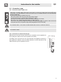
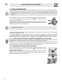
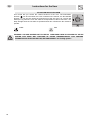
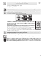
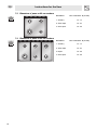
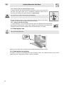
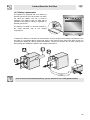
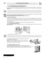
Contents
1. INSTRUCTIONS FOR USE ..................................................................................................... 4
2. INSTRUCTIONS FOR DISPOSAL – OUR CONCERN FOR THE ENVIRONMENT ............... 6
3. INSTALLING THE APPLIANCE .............................................................................................. 7
3.1 Wall fixing ........................................................................................................................................................ 7
3.2 Electrical connection ....................................................................................................................................... 8
3.3 Room ventilation ............................................................................................................................................. 8
3.4 Extraction of the combustion products ............................................................................................................ 8
3.5 Connection to gas ........................................................................................................................................... 9
4. ADAPTATION TO DIFFERENT TYPES OF GAS ................................................................. 10
4.1 Replacement of the cooking hob nozzles ..................................................................................................... 10
4.2 Burner and nozzle characteristics table (60 cm model) ................................................................................ 11
4.3 Burner and nozzle characteristics table (90 cm model) ................................................................................ 12
4.4 Arrangement of the burners on the cooking hob ........................................................................................... 13
4.5 Adjustment of oven burner ............................................................................................................................ 13
5. FINAL OPERATIONS ............................................................................................................ 14
5.1 Regulation of the hob burner minimum for natural gas ................................................................................. 14
5.2 Regulation of the hob burner minimum for liquid gas .................................................................................... 14
5.3 Positioning and levelling the appliance (depending on the model) ............................................................... 14
5.4 Adjustment of the oven burner minimum ...................................................................................................... 14
6. THE CONTROL PANEL ........................................................................................................ 15
7. USING THE COOKING HOB ................................................................................................ 17
7.1 Lighting the hob burners ............................................................................................................................... 17
7.2 Practical hints for using the hob burners ....................................................................................................... 17
7.3 Diameters of pans on 60-cm cookers ........................................................................................................... 18
7.4 Diameters of pans on 90-cm cookers ........................................................................................................... 18
8. USING THE OVEN ................................................................................................................ 19
8.1 Warnings and general advice ........................................................................................................................ 19
8.2 Cooling system ........................................................................................................................................... 19
8.3 Using the gas oven ....................................................................................................................................... 19
8.4 Using the gas grill .......................................................................................................................................... 20
8.5 Storage compartment .................................................................................................................................... 21
9. AVAILABLE ACCESSORIES ................................................................................................ 22
10. CLEANING AND MAINTENANCE ....................................................................................... 23
10.1 Ordinary daily cleaning ................................................................................................................................ 23
10.2 Cleaning the parts of the cooking hob ......................................................................................................... 23
10.3 Cleaning the oven ....................................................................................................................................... 24
10.4 Cleaning the door glazing ........................................................................................................................... 24
10.5 Battery replacement .................................................................................................................................... 25
11. EXTRAORDINARY MAINTENANCE .................................................................................. 26
11.1 Lubrication of gas oven taps and thermostat .............................................................................................. 26
11.2 Oven fan failure ........................................................................................................................................... 26
11.3 Changing the light bulb ............................................................................................................................... 26
11.4 Removing the doors .................................................................................................................................... 26
11.5 Removing the door seal .............................................................................................................................. 26
INSTRUCTIONS FOR THE USER: these contain user advice, description of the commands and the
correct procedures for cleaning and maintenance of the appliance.
INSTRUCTIONS FOR THE INSTALLER: these instructions are intended for the qualified technician
who must carry out an adequate inspection of the gas system, perform the installation, put the appliance
into operation and test it.
3
Precautions for use
1. INSTRUCTIONS FOR USE
THIS MANUAL IS AN INTEGRAL PART OF THE APPLIANCE AND THEREFORE IT MUST BE KEPT
IN ITS ENTIRETY AND IN AN ACCESSIBLE PLACE FOR THE WHOLE WORKING LIFE OF THE
HOB. WE ADVISE YOU TO READ THIS MANUAL AND ALL THE INSTRUCTIONS THEREIN
CAREFULLY BEFORE USING THE HOB. INSTALLATION MUST BE CARRIED OUT BY QUALIFIED
PERSONNEL IN ACCORDANCE WITH THE REGULATIONS IN FORCE. THIS APPLIANCE IS
INTENDED FOR DOMESTIC USE AND CONFORMS TO THE EEC DIRECTIVES CURRENTLY IN
FORCE. THE APPLIANCE HAS BEEN BUILT TO CARRY OUT THE FOLLOWING FUNCTIONS:
COOKING AND HEATING UP FOOD; ALL OTHER USES ARE CONSIDERED UNSUITABLE.
THE MANUFACTURER DECLINES ALL RESPONSIBILITY FOR IMPROPER USE.
DO NOT DISCARD PACKAGING IN THE HOME ENVIRONMENT. SEPARATE THE VARIOUS
WASTE MATERIALS AND TAKE THEM TO THE NEAREST DIFFERENTIATED WASTE
COLLECTION CENTRE.
IT IS OBLIGATORY FOR ALL ELECTRICAL SYSTEMS TO BE GROUNDED INCOMPLIANCE WITH
ELECTRICAL SYSTEM SAFETY REGULATIONS.
THE PLUG TO BE CONNECTED TO THE POWER SUPPLY CABLE AND ITS SOCKET MUST BE OF
THE SAME TYPE AND CONFORM TO THE REGULATIONS IN FORCE.
THE SOCKET MUST BE ACCESSIBLE AFTER THE APPLIANCE IS INSTALLED.
NEVER DISCONNECT THE PLUG BY PULLING ON THE CABLE.
IMMEDIATELY AFTER INSTALLATION, CARRY OUT A QUICK TEST ON THE APPLIANCE
FOLLOWING THE INSTRUCTIONS PROVIDED LATER IN THIS MANUAL. SHOULD THE
APPLIANCE NOT FUNCTION, DISCONNECT IT FROM THE POWER SUPPLY AND CALL THE
NEAREST TECHNICAL SUPPORT CENTRE.
NEVER ATTEMPT TO REPAIR THE APPLIANCE.
ALWAYS CHECK THAT THE CONTROL KNOBS ARE IN THE (OFF) POSITION WHEN YOU FINISH
USING THE APPLIANCE.
NEVER PLACE FLAMMABLE OBJECTS IN THE OVEN: IF IT SHOULD ACCIDENTALLY BE
SWITCHED ON, THIS MIGHT CAUSE A FIRE.
THE IDENTIFICATION PLATE WITH THE TECHNICAL DATA, SERIAL NUMBER AND BRAND NAME
IS IN A VISIBLE POSITION INSIDE THE STORAGE COMPARTMENT.
THE PLATE MUST NOT BE REMOVED.
NEVER PLACE PANS WITH BOTTOMS WHICH ARE NOT PERFECTLY FLAT AND SMOOTH ON
THE COOKING HOB PAN STANDS.
NEVER USE PANS OR GRIDDLE PLATES WHICH PROJECT BEYOND THE OUTSIDE EDGE OF
THE HOB.
HOLD THE GLASS LID WITH YOUR HAND WHILE LOWERING IT.
WARNING: THE GLASS LID CAN SPLINTER IF OVERHEATED.
TURN OFF ALL THE BURNERS AND WAIT FOR THEM TO COOL DOWN BEFORE CLOSING IT.
DURING USE THE APPLIANCE BECOMES VERY HOT. TAKE CARE NOT TO TOUCH THE HEATING
ELEMENTS INSIDE THE OVEN.
THE APPLIANCE IS INTENDED FOR USE BY ADULTS. DO NOT ALLOW CHILDREN TO GO NEAR
IT OR PLAY WITH IT.
WHEN THE GRILL IS WORKING THE ACCESSIBLE PARTS CAN BECOME VERY HOT: KEEP
CHILDREN AT A SAFE DISTANCE.
IF THE APPLIANCE IS PLACED ON A PEDESTAL IT MUST BE INSTALLED SO THAT IT CANNOT
SLIDE OFF.
4
Precautions for use
IF THE COOKING PRODUCTS ARE INSTALLED IN MOTOR VEHICLES (FOR EXAMPLE, CAMPER
VANS, CARAVANS ETC.) THEY MUST ONLY BE USED WHEN THE VEHICLE IS STOPPED.
INSTALL THE PRODUCT SO THAT WHEN OPENING THE DRAWERS AND DOORS OF UNITS
POSITIONED AT THE LEVEL OF THE COOKING HOB THERE IS NO POSSIBILITY OF MAKING
CONTACT WITH PANS POSITIONED ON TOP OF IT.
THIS APPLIANCE IS MARKED ACCORDING TO THE EUROPEAN DIRECTIVE 2002/96/EC ON
WASTE ELECTRICAL AND ELECTRONIC EQUIPMENT (WEEE).
THIS DIRECTIVE DETERMINES THE STANDARDS FOR THE COLLECTION AND RECYCLING OF
WASTE ELECTRICAL AND ELECTRONIC EQUIPMENT APPLICABLE THROUGHOUT THE
EUROPEAN UNION.
BEFORE THE APPLIANCE IS PUT INTO OPERATION, ALL LABELS AND PROTECTIVE FILMS
APPLIED INSIDE OR OUTSIDE MUST BE REMOVED.
WARNING: THE COOLING FAN DOES NOT FUNCTION WHEN THE POWER IS CUT. YOU ARE
THEREFORE ADVISED NOT TO USE THE OVEN IN THESE CIRCUMSTANCES. FOR FURTHER
INFORMATION ON THE COOLING FAN, SEE PARAGRAPH “8.2 Cooling system”
The manufacturer cannot be held liable for damage to persons or things caused by failure to
observe the above instructions, by interference with any part of the appliance or by the use of
non-original spare parts.
5
The environment – Recycling instructions
2. INSTRUCTIONS FOR DISPOSAL – OUR CONCERN FOR THE
ENVIRONMENT
Our household appliances are only packaged using non-polluting, environmentally friendly, recyclable
materials. Please help by disposing of the packaging correctly. You can obtain the addresses of
collection, recycling and disposal centres from your retailer or from the competent local organisations.
Never leave all or part of the packaging lying around.
Your old appliance also needs to be disposed of correctly.
Important: deliver the appliance to the local agency authorised for the collection of household appliances
no longer in use.
Correct disposal enables intelligent recovery of valuable materials. Refrigeration appliances contain
gases which may damage the environment; it is therefore important to ensure that the refrigeration
circuit pipelines are not damaged before the competent service has accepted delivery of the appliance.
Before disposing of your appliance it is important to remove doors and leave shelves in their normal
positions to ensure that children cannot accidentally become trapped inside while playing. It is also
necessary to cut the connecting cable to the power supply network, removing it along with the plug.
DO NOT DISCARD PACKAGING IN THE HOME ENVIRONMENT. SEPARATE THE VARIOUS
WASTE MATERIALS AND TAKE THEM TO THE NEAREST DIFFERENTIATED WASTE
COLLECTION CENTRE.
INFORMATION FOR USERS:
Pursuant to Directives 2002/95/EC, 2002/96/EC and 2003/108/EC relating to the reduction of the use of
hazardous substances in electrical and electronic appliances, as well as to the disposal of refuse, the
crossed out bin symbol on the appliance indicates that at the end of the useful life of the product, it must
be collected separately from other refuse. Therefore, at the end of the product's working life, the user
must deliver it to the appropriate differentiated collection centres for electrical and electronic waste, or
deliver it back to the retailer when purchasing an equivalent product, on a one-for-one basis. Adequate
differentiated collection for the subsequent forwarding of the decommissioned product to recycling,
processing and ecologically compatible disposal contributes to avoiding any negative effects on the
environment and on health and promotes the recycling of the appliance's constituent materials. Illicit
disposal of the product by the user will lead to the application of administrative sanctions.
6
Instructions for the installer
3. INSTALLING THE APPLIANCE
The appliance must be installed by a qualified technician and according to the regulations in force.
Depending on the type of installation, it belongs to class 1 (Fig.A) or to class 2-subclass 1 (Fig.B-C).
This appliance may be installed next to a wall which is higher than the appliance, with a minimum
distance of 50 mm from the side of the appliance, as shown in drawings A and B relative to the
installation classes. Any wall cupboards or ventilation hoods must be at a distance of at least 750 mm
above the work surface.
A)
B)
Built-in appliance
Free-standing installation
C)
Appliances equipped with a gas cylinder compartment and electric oven can only be installed as freestanding (see fig. B).
3.1 Wall fixing
In order to avoid the cooker tipping over it must be attached
to the wall by means of a chain, as described below:
• Horizontally stretch out the chain attached to the cooker
• so that the other end touches the wall.
• Make a mark on the wall in the position where the hole is
to be drilled.
• Drill the hole, insert a wall plug and attach the chain.
• Move the cooker up against the wall.
7
Instructions for the installer
3.2 Electrical connection
Make sure the voltage and the cross-section of the power supply line match the specifications indicated
on the identification plate positioned in the storage compartment.
Do not remove this plate for any reason.
If the appliance is connected to the power supply network by means of a fixed connection, install a
multipolar cut-out device on the power supply line, with a contact opening distance equal to or greater
than 3 mm, located near the appliance and in an easily reachable position.
Connection to the power supply network may be fixed or with a plug and socket. In the latter case the
plug and socket must be suitable for the cable employed and conform to the regulations in force.
Regardless of the type of connection, the appliance must be earthed. Before connection, make sure that
the power supply line is suitably earthed. Avoid the use of adapters and shunts.
1 - For operation on 220-240V~: use a H05V2V2-F type three-core
2
220-240V~
1.5 mm
cable:
3 x 1.5 mm²
20 mm
WARNING: THE VALUES INDICATED ABOVE REFER TO THE CROSS-SECTION OF THE
INTERNAL CONDUCTOR.
Warning: only some of the 90 cm models can be connected with two or three phases.
3.3 Room ventilation
The room containing the appliance should have a permanent air supply in accordance with the
regulations in force. The room where the appliance is installed must have enough air flow for the regular
combustion of gas and for the air exchange needed in the room itself. The air vents, protected by grills,
must be suitably dimensioned in compliance with the current regulations and positioned so that no part
of them is obstructed.
The cooker must be kept adequately ventilated in order to eliminate the heat and humidity produced by
cooking: in particular, after prolonged use, you are recommended to open a window or to increase the
speed of any fans.
3.4 Extraction of the combustion products
The combustion products must be extracted by means of hoods connected to a natural draught chimney
whose efficiency is certain or via forced extraction. An efficient extraction system requires precision
planning by a specialist qualified in this area and must comply with the positions and distances indicated
by the regulations. When the job is complete, the installer must issue a certificate of conformity.
8
Instructions for the installer
3.5 Connection to gas
3.5.1 Connection with a rubber hose
Installation of the standards-compliant rubber hose must be carried out so that the hose length is no
greater than 1.5 metres. Make sure that the hose does not come into contact with moving parts and is
not squashed. The inside diameter of the hose must be 8 mm for LIQUID GAS and 13 mm for NATURAL
GAS and TOWN GAS.
Verify that all the following conditions are met:
• the hose is fixed to the hose connection with safety clamps;
• no part of the hose is in contact with hot walls (max. 50°C);
• the hose is not under traction or tension and has no tight curves or twists;
• the hose is not in contact with sharp objects or sharp corners;
• if the hose is not perfectly airtight and leaks gas, do not try and repair it: replace it with a new hose;
• verify that the hose is not past its expiry date (serigraphed on the hose itself).
CONNECTION USING RUBBER HOSES COMPLYING WITH THE CURRENT REGULATIONS IS
ONLY PERMITTED IF THE HOSE CAN BE INSPECTED ALONG ITS ENTIRE LENGTH.
THE TIGHTENING TORQUE BETWEEN CONNECTIONS THAT INCORPORATE THE GASKET MUST
NOT EXCEED 10NM
3.5.2 Connection to natural and LPG gas
Make the gas connection using a rubber hose in accordance to the regulations in
force (verify if the mark of such norm is printed on the tube).
Accurately screw connector A to the gas tube B of the appliance ensuring to
place gasket C in between. Place the rubber tube D on connector A and fix it with
clip E conforming to the regulations in force.
9
Instructions for the installer
4. ADAPTATION TO DIFFERENT TYPES OF GAS
Before carrying out the following operations, disconnect the appliance from the electricity supply.
The appliance is preset for natural gas G20 (2H) at a pressure of 20 mbar. In the case of operation with
other types of gas the burner nozzles must be changed and the minimum flame adjusted on the gas
taps. To change the nozzles, proceed as described in the following paragraphs.
4.1 Replacement of the cooking hob nozzles
1 Extract the pan stands and remove all the caps and flame-spreader crowns;
2 Unscrew the burner nozzles with a 7 mm socket wrench;
3 Replace the burner nozzles according to the type of gas to be used (see paragraphs “4.2 Burner and
nozzle characteristics table (60 cm model)” and “4.3 Burner and nozzle characteristics table (90 cm
model)”).
4 Replace the burners in the correct position.
The nozzles for using town gas (G110 – 8 mbar) are available from authorised service centres.
10
Instructions for the installer
4.2 Burner and nozzle characteristics table (60 cm model)
Burner
Auxiliary
Semi-rapid
Ultra-rapid
Oven
Grill
Burner
Auxiliary
Semi-rapid
Ultra-rapid
Oven
Grill
Rated heating
capacity (kW)
1.05
1.8
3.9
3.2
2.9
Rated heating
capacity
(kW)
1.05
1.8
3.9
3.2
2.9
Nozzle
diameter 1/
100 mm
50
65
100
87
87
LIQUID GAS – G30/G31 28/37 mbar
By-pass
Reduced
Capacity
1/100
capacity
g/h G30
mm
(W)
30
400
76
33
500
127
65
1600
284
50
900
233
211
Capacity
g/h G31
75
125
279
229
207
NATURAL GAS – G20 20 mbar
Nozzle
diameter
1/100 mm
72 (X)
97 (Z)
135 (K)
130
130
Reduced
capacity
(W)
400
500
1600
900
-
11
Instructions for the installer
4.3 Burner and nozzle characteristics table (90 cm model)
Burner
Auxiliary
Semi-rapid
Rapid
Ultra-rapid
Oven
Grill
Burner
Auxiliary
Semi-rapid
Rapid
Ultra-rapid
Oven
Grill
12
Rated heating
capacity (kW)
1.05
1.8
3.0
3.9
5.2
4.0
Rated heating
capacity
(kW)
1.05
1.8
3.0
3.9
5.2
4.0
Nozzle
diameter
1/100 mm
50
65
85
100
110
100
LIQUID GAS – G30/G31 28/37 mbar
By-pass
Reduced
Capacity
1/100 mm
capacity (W)
g/h G30
30
33
45
65
59
-
400
500
800
1600
1300
-
76
127
218
284
378
291
NATURAL GAS – G20 20 mbar
Nozzle
diameter
1/100 mm
72
97
115
135
164
150
Reduced
capacity
(W)
400
500
800
1600
1300
-
Capacity
g/h G31
75
125
214
279
371
286
Instructions for the installer
4.4 Arrangement of the burners on the cooking hob
BURNERS
1. Auxiliary
2. Semi-rapid
4. Ultra-rapid
BURNERS
1. Auxiliary
2. Semi-rapid
3. Rapid
4. Ultra-rapid
4.5 Adjustment of oven burner
To adjust the oven burner you need to open the oven door and carry out
the following operations:
• Remove the oven basin and its rack.
• Lift up the oven surface and pull it outwards.
4.5.1 Replacing the oven and grill burner nozzles
• Loosen the oven burner fixing screw A.
• Push burner B towards the right until the nozzle is accessible.
• Using a 13 socket wrench, replace the nozzle, inserting a new nozzle
suitable for the type of gas to be used (see paragraphs “4.2 Burner
and nozzle characteristics table (60 cm model)” and “4.3 Burner and
nozzle characteristics table (90 cm model)“).
4.5.2 Primary air adjustment for the oven and grill burners
• Loosen adjustment screw “A” of the air regulation sleeve.
• Turn adjustment sleeve “B” to the position that corresponds to the
type of gas to be used according to the table below.
• Tighten the adjustment screw and restore the seals.
• When the operation is completed, reassemble the burner correctly.
OVEN
GRILL
X=
NATURAL GAS
5 mm
G 30/31 (LPG)
10 mm
X=
NATURAL GAS
5 mm
G 30/31 (LPG)
15 mm
13
Instructions for the installer
5. FINAL OPERATIONS
After replacing the nozzles, reposition the flame-spreader crowns, the burner caps and the pan stands.
Following adjustment to a gas other than the preset one, replace the gas adjustment label fixed to the
appliance with the one corresponding to the new gas. The label is inserted inside the pack together with
the nozzles.
5.1 Regulation of the hob burner minimum for natural gas
Light the burner and turn it to the minimum position . Extract the gas tap knob
and turn the adjustment screw at the side of the tap rod until the correct
minimum flame is achieved.
Refit the knob and verify that the burner flame is stable (when turning the knob
rapidly from the maximum to the minimum position the flame must not go out).
Repeat the operation on all the gas taps.
For models with valves, keep the knob at the minimum level for a few seconds to keep the flame lit and
to activate the safety device.
5.2 Regulation of the hob burner minimum for liquid gas
In order to adjust the minimum setting with liquid gas, the screw at the side of the tap rod must be
tightened clockwise all the way.
The bypass diameters for each individual burner are shown in paragraphs “4.2 Burner and nozzle
characteristics table (60 cm model)” and “4.3 Burner and nozzle characteristics table (90 cm model)”.
When the adjustment is completed, restore the sealing of the by-passes with paint or another material.
5.3 Positioning and levelling the appliance (depending on the model)
After making the electrical and gas connections, level the appliance on the floor by means of its four
adjustable feet. For good cooking results, the appliance must be properly levelled.
Depending on the model you have purchased, the foot height adjustment range may vary from 70 to 95
mm and from 110 to 160 mm. These heights refer to the distance between the highest point of the foot
(fixed part) and the lowest point (movable part which rests on the floor).
5.4 Adjustment of the oven burner minimum
Light the burner and turn it to the minimum position . Extract the gas tap knob
and turn the adjustment screw at the side of the tap rod until the correct
minimum flame is achieved.
Refit the knob and verify that the burner flame is stable (when turning the knob
rapidly from the maximum to the minimum position the flame must not go out).
Repeat the operation on all the gas taps.
14
Instructions for the installer
6. THE CONTROL PANEL
All the cooker controls are grouped together on the front panel. The symbols used are described in the
table below.
TIMER KNOB
REAR CENTRAL BURNER KNOB
2-FUNCTION SELECTION KNOB
FRONT CENTRAL BURNER KNOB
GAS GRILL AND GAS OVEN
THERMOSTAT KNOB
REAR RIGHT-HAND BURNER KNOB
FRONT LEFT-HAND BURNER KNOB
FRONT RIGHT-HAND BURNER
KNOB
REAR LEFT-HAND BURNER KNOB
HOB BURNER CONTROL KNOB
To light the flame, press the knob and turn it anticlockwise to the minimum flame
symbol
. To adjust the flame, turn the knob to the zone between the maximum (
and minimum (
) settings. To turn off the burner, turn the knob to the
)
position.
TIMER KNOB
In order to use the timer, the buzzer must be set by turning the knob in a clockwise
direction. The numbers correspond to minutes (maximum 55 minutes). Adjustment is
progressive and intermediate positions between the figures can be used. The end of
cooking buzzer does not interrupt operation of the oven.
GAS GRILL AND GAS OVEN THERMOSTAT KNOB
This knob allows the gas burner and the gas grill inside the oven to be lit. The cooking
temperature of the gas oven is selected by turning the knob anticlockwise to the
desired setting, between Min. and 275°C.
Cooking can be carried out with the gas grill by turning the knob to position .
To find out how to light the gas oven, see paragraph “8.3 Using the gas oven”.
To find out how to light the gas oven, see paragraph “8.4 Using the gas grill”.
15
Instructions for the User
2-FUNCTION SELECTION KNOB
This control lets you access the various functions of the oven. The illumination
function ( ) can be used when the oven is switched off. However, the fan-assisted
function ( ) can only be used if the lower burner of the gas oven is lit. The fan will
start operating when the oven has reached a temperature of about 120-130°C. The
lamp will light when the fan starts to operate and will turn off when the fan ceases to
operate.
LAMP
FAN
WARNING: YOU ARE ADVISED NOT TO USE THE OVEN WHEN THERE IS A POWER CUT AS THE
COOLING FAN DOES NOT FUNCTION IN THOSE CIRCUMSTANCES. FOR FURTHER
INFORMATION ON THE COOLING FAN, SEE PARAGRAPH “8.2 Cooling system”
16
Instructions for the User
7. USING THE COOKING HOB
7.1 Lighting the hob burners
Before lighting the hob burners, check that the flame-spreader crowns are correctly in place with their
respective burner caps, making sure that the holes A in the flame-spreaders are aligned with the plugs
and thermocouples.
The optional pan stand B is for use with woks.
To prevent damage to the cooking hob, the cooker comes complete with a raised pan stand C for use
underneath pans more than 26 cm in diameter.
The reduction C supplied is for use with small pans as well.
The burner controlled by each knob is shown next to the knob.
The appliance is equipped with an electronic ignition device. Simply press the knob
and turn it anticlockwise to the minimum flame symbol , until it lights. If it does not
light in the first 15 seconds, position the knob on 0 and wait at least 60 seconds
before trying to light it again.
On valved models, once the burner is lit, keep the knob pressed for a few seconds to
give the thermocouple time to heat up. The burner may go out when the knob is
released: in this case, the thermocouple has not heated up sufficiently.
Wait a few moments and repeat the operation keeping the knob pressed for longer.
This is not necessary on burners that are not equipped with a thermocouple.
If the spark is too weak or it is absent, you are advised to replace the battery - see
paragraph “10.5 Battery replacement”.
On models with a thermocouple, if the burners should go out accidentally a safety device will be tripped,
cutting off the gas supply even if the gas tap is open. In this case, turn the knob to the OFF position and
wait at least 60 seconds before trying to light the burner again.
7.2 Practical hints for using the hob burners
For better burner efficiency and to minimise gas consumption: use pans with lids and of a suitable size
for the burner, so that the flames do not reach up the sides of the pan (see paragraphs “7.3 Diameters of
pans on 60-cm cookers” and “7.4 Diameters of pans on 90-cm cookers”). Once the contents come to the
boil, turn down the flame far enough to ensure that the liquid does not boil over. To prevent burns or
damage to the hob during cooking, all pans or griddle plates must be placed inside the perimeter of the
hob. All pans must have smooth, flat bottoms. Take the greatest care when using fats or oils since they
may catch fire if overheated. If the flame accidentally goes out, turn off the control knob and wait at least
1 minute before trying to re-light the burner.
17
Instructions for the User
7.3 Diameters of pans on 60-cm cookers
BURNERS
MIN. AND MAX. Ø (IN CM)
1. Auxiliary
12 - 14
2. Semi-rapid
16 - 24
4. Ultra-rapid
18 - 26
7.4 Diameters of pans on 90-cm cookers
18
BURNERS
MIN. AND MAX. Ø (IN CM)
1. Auxiliary
12 - 14
2. Semi-rapid
16 - 24
3. Rapid
18 - 26
4. Ultra-rapid
18 - 26
Instructions for the User
8. USING THE OVEN
8.1 Warnings and general advice
When the gas oven and gas grill are used for the first time, they should be heated to the maximum
temperature (275°C) for long enough to burn off any oily residues left by the manufacturing process,
which could contaminate foods with unpleasant smells.
WARNING: the gas oven must be lit with the oven door open. The oven is equipped with a safety
system that blocks ignition of the burner if the door is closed. If you make a mistake in the
lighting procedure, open the oven door and wait a few moments before trying to light it again.
WHILE COOKING DESSERTS AND VEGETABLES, LIQUID MAY DRIP FROM THE BOTTOM OF THE
DOOR. THIS IS A NATURAL PHYSICAL PHENOMENON WHICH MAINLY OCCURS WHEN
PREHEATING HAS NOT TAKEN PLACE. IN ORDER TO AVOID THIS, OPEN THE DOOR VERY
CAREFULLY A COUPLE OF TIMES WHILE COOKING.
To prevent any steam in the oven from creating problems, open the door in two
stages: half open (5 cm approx.) for 4-5 seconds and then fully open. To access
food, always leave the door open as short a time as possible to prevent the
temperature in the oven from falling and ruining the food.
8.2
Cooling system
This system keeps the door and internal components of the oven at a lower temperature through forced
recirculation of cool air, guaranteeing increased safety and a longer life for the electrical appliance.
The tangential cooling system remains active even after cooking has finished and continues working
when the oven has been switched off in order to disperse all the heat that has built up inside. This
mechanism allows all the furniture units surrounding the appliance to be protected, preventing them from
overheating.
WARNING: THE COOLING FAN DOES NOT FUNCTION WHEN THE POWER IS CUT. YOU ARE
THEREFORE ADVISED NOT TO USE THE OVEN IN THESE CIRCUMSTANCES.
8.3 Using the gas oven
8.3.1 Electronic spark ignition
Open the oven door fully, press the thermostat knob and turn it anticlockwise to the
maximum temperature; the electric spark ignition is activated automatically. When
the oven is lit, keep the knob pressed down for a few seconds to allow the
thermocouple to heat up.
If the burner does not ignite after 15 seconds, interrupt the attempt to light it, open
the oven door completely and do not try to light it again for at least 1 minute.
If the spark is too weak or it is absent, you are advised to replace the battery - see
paragraph “10.5 Battery replacement”.
8.3.2 Manual ignition
Open the oven door fully and turn the thermostat knob while keeping it pressed in.
Bring a lighted match close to the mouth of flame pipe A at the centre of the oven
surface and press the thermostat knob. Once it is lit, keep the knob pressed down
for a few seconds to allow the thermocouple to heat up and make sure that it has
remained lit by looking through inspection hole B. The cooking temperature is
selected by turning the knob clockwise to the desired setting, between MIN and
275° C.
If the burner is extinguished accidentally, a safety valve will be activated to interrupt the flow of gas. To light
it again, first turn the knob to the OFF position ( ) and wait for about one minute. Then relight the gas
following the normal procedures.
19
Instructions for the User
8.4 Using the gas grill
8.4.1 Electrical ignition of the gas grill
Having opened the oven door, press the knob and turn it clockwise to the grill
position , when a spark will light the burner.
Once the burner is lit, continue to press down the knob for about 10 seconds. If
the burner does not remain lit when the knob is released, leave it for about one
minute before trying to light it again.
If the burner goes out accidentally while in use, turn the knob to the off position
and wait for at least one minute before relighting it.
If the spark is too weak or it is absent, you are advised to replace the battery - see
paragraph “10.5 Battery replacement”.
During a power cut, the grill burner can still be lit by using a match.
8.4.2 Manual ignition of the gas grill
Having opened the oven door, press the knob and turn it clockwise to the grill position , then light the
upper burner of the oven with a match.
Once the burner is lit, continue to press down the knob for about 10 seconds. If the burner does not
remain lit when the knob is released, leave it for about one minute before trying to light it again. If the
burner goes out accidentally, turn the knob to the off position
and wait for at least one minute before
relighting it.
WARNING: IT IS IMPOSSIBLE TO USE THE GAS GRILL AND THE GAS OVEN AT THE SAME TIME
8.4.3 How to use the grill
When the oven has been successfully lit, allow it to heat up for 5 minutes before putting in food.
Food must be seasoned before cooking. Foods should also be coated with oil or melted butter before
cooking. Use the oven tray to collect juice.
The foods to be cooked must be placed on the oven rack, which must then be placed on one of the
runners fitted in the various types of ovens, following the guidelines below:
FOODS
RACK ON THE SHELF
Flat, thin pieces of meat
3
Rolled roasts
2-3
Poultry
2-3
PRECAUTIONS
Grilling processes must never last more than 30 minutes.
•
•
•
•
The oven door must be opened at the first step during grill cooking operations.
Accessible parts may be very hot during and after use of the grill; keep children well away
from the appliance.
When using the oven, remove all unused trays and racks from its interior.
During cooking, do not cover the bottom of the oven with aluminium or tin foil and do not
place pans or oven plates on it as this may damage the enamel coating. If you wish to use
greaseproof paper, place it so that it will not interfere with the hot air circulation inside the
oven.
WARNING: THE COOLING FAN DOES NOT FUNCTION WHEN THE POWER IS CUT. YOU ARE
THEREFORE ADVISED NOT TO USE THE OVEN IN THESE CIRCUMSTANCES.
20
Instructions for the User
8.5 Storage compartment
The storage compartment is in the bottom of the cooker, underneath the oven.
To open it, pull on the top of the door.
Do not open the storage compartment when the oven is on and still hot. The temperature inside it may
be very high.
Never use it to store flammable materials such as rags, paper, etc.; it is intended for storing the
appliance's metal accessories only.
21
Instructions for the User
9. AVAILABLE ACCESSORIES
The oven features 3 runners for positioning pans and racks at
different heights.
Oven rack: for cooking food inside dishes, small cakes, roasts or
foods that require slight grilling.
Plate rack: for placing on top of a pan for cooking foods which may
drip.
Oven plate: useful for collecting fat from foods placed on the rack
above.
Avoid direct contact with racks and plates which have just been used for cooking in
the oven; they may be very hot. You are therefore advised to use cloth pot holders or
oven gloves.
Some models are not provided with all accessories.
The oven accessories intended to come into contact with food are made of materials that comply with
the provisions of Directive 89/109/EEC, dated 21/12/88, and of Legislative Decree 108, dated 25/01/92.
22
Instructions for the User
10.CLEANING AND MAINTENANCE
Before performing any operations, switch off the power supply to the appliance.
Do not use a steam jet for cleaning the inside of the oven.
To keep stainless steel in good condition it should be cleaned regularly after every use
of the cooker, after it has cooled.
10.1 Ordinary daily cleaning
To clean and preserve the stainless steel surfaces, always use only specific products that do not contain
abrasives or chlorine-based acids.
How to use: pour the product onto a damp cloth and wipe the surface, rinse thoroughly and dry with a
soft cloth or chamois leather.
10.1.1 Food stains or residues
Do not use metallic sponges or sharp scrapers as they will damage the surface.
Use normal non-abrasive products and a wooden or plastic tool if necessary. Rinse thoroughly
and dry with a soft cloth or chamois leather.
Do not allow residues of sugary foods (such as jam) to set inside the oven. If left to set for too
long, they might damage the enamel lining of the oven.
10.2 Cleaning the parts of the cooking hob
10.2.1 Pan stands
Remove the pan stands and clean them with warm water and non-abrasive detergent, making sure to
remove any encrustation. Replace them on the cooking hob.
Continuous contact between the pan stands and the flame can cause modifications to the enamel over
time in those parts exposed to heat. This is a completely natural phenomenon which has no effect on the
operation of this component.
Warning:
If using cast iron pan stands (optional, not supplied), at the end of cooking using pans with aluminium
bases, you may find white residues on the pan stands. These residues are usually caused by the pan
base rubbing against the pan stand and are difficult to remove with normal cleaning. Using abrasive or
excessively aggressive products to clean the pan stand could damage its enamel surface.
23
Instructions for the User
10.2.2 Burner caps and flame spreader crowns
For easier cleaning, the caps and the flame spreader crowns can be removed;
wash them with warm water and a non-abrasive detergent making sure to
remove any encrustation and wait until they are perfectly dry.
WARNING: never wash these parts in a dishwasher.
They can be left to soak in warm water and detergent.
Replace the flame spreader crowns, making sure that they are correctly in place
with their respective burner caps, making sure that the holes A in the flamespreaders are aligned with the igniters and thermocouples.
10.2.3 Igniters and thermocouples
For correct operation, on those models that have them, the igniters and thermocouples
must always be perfectly clean. Check them frequently and clean them with a damp cloth
if necessary. Remove any dry residues with a wooden toothpick or a needle.
10.3 Cleaning the oven
For best oven upkeep, clean it regularly after having allowed it to cool.
Take out all removable parts.
Clean the oven racks with hot water and non-abrasive detergent. Rinse and dry.
10.4 Cleaning the door glazing
The glass in the door should always be kept thoroughly clean. Use absorbent kitchen roll; remove
stubborn dirt with a damp sponge and an ordinary detergent.
24
Instructions for the User
10.5 Battery replacement
The appliance is equipped with a 9V battery to
light the gas burners even when there is a power
cut. When the battery runs out, it must be
replaced; if the battery is flat, no spark will be
provided to the igniters, making it impossible to
light the gas burners.
The battery is located in a special container in
the inside left-hand wall of the storage
compartment.
To replace the battery, its container C must be taken out of housing A in the storage compartment. Run
the head of a screwdriver B into opening D, press to the left and at the same time slide out the box
containing the battery E. Having replaced the battery, reinsert the container into its seat, making sure
that opening D is towards the inside of the storage compartment.
In order to reduce environmental pollution, you are advised to use rechargeable batteries.
25
Instructions for the User
11. EXTRAORDINARY MAINTENANCE
The oven may require extraordinary maintenance or replacement of parts subject to wear such as
gaskets, bulbs, etc. The following instructions describe how to carry out these minor maintenance
operations.
Before any intervention that requires access to live parts, disconnect the power supply of the appliance.
11.1 Lubrication of gas oven taps and thermostat
Over time, the gas taps and the gas oven thermostat may become difficult to turn and get blocked. Clean
them internally and replace the lubrication grease.
This operation must be carried out by a specialised technician.
11.2 Oven fan failure
If there is a power cut, the oven fan function cannot be used. To check the operation of the fan, the user
needs to turn on the lower burner of the gas oven, set the selector knob to the fan position ( ) and wait
for the oven's internal temperature to reach or exceed 120-130°C. If the fan does not start to operate,
this indicates a fault.
In the case of a fault, do not attempt to repair it; instead, contact technical support.
11.3 Changing the light bulb
Remove bulb protector A by turning it anticlockwise and replace bulb B with a similar one (25 W). Re-fit
bulb protector A.
Use oven bulbs only (T 300°C).
11.4 Removing the doors
Lift the levers B and take hold of the two sides of the door with
both hands near the hinges A.
Raise the door to an angle of about 45° and remove it. To
reassemble, fit the hinges A into their grooves, then lower the
door into place and release the levers B.
11.5 Removing the door seal
To permit thorough cleaning of the oven, the seal may be removed.
Before removing the seal, take off the door as described above. Once the
door has been taken off, lift the tabs at the corners as shown in the figure.
914773679/ B
26