1
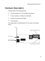
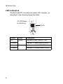
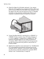
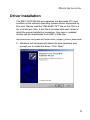
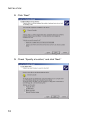
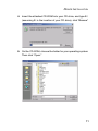
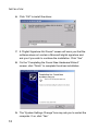
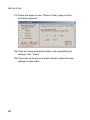
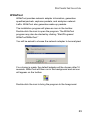
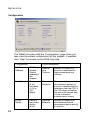
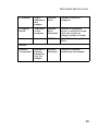
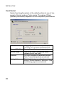
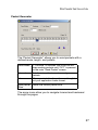
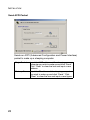
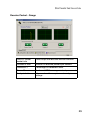
SMC1255TX
Barricade PCI
User Guide
From SMC’s Barricade line of award-winning workgroup LAN solutions
38 Tesla
Irvine, CA 92618
Phone: (949) 679-8000
December 2002
Pub. No:150000026800A
Part No: 01-111337-006
Copyright
Information furnished by SMC Networks, Inc. (SMC) is believed to be accurate and reliable.
However, no responsibility is assumed by SMC for its use, nor for any infringements of patents
or other rights of third parties which may result from its use. No license is granted by
implication or otherwise under any patent or patent rights of SMC. SMC reserves the right to
change specifications at any time without notice.
Copyright © 2002 by
SMC Networks, Inc.
38 Tesla
Irvine, CA 92618
All rights reserved. Printed in Taiwan
Trademarks:
SMC is a registered trademark; and EZ Networking is a trademark of SMC Networks, Inc. Other
product and company names are trademarks or registered trademarks of their respective
holders.
LIMITED WARRANTY
Limited Warranty Statement: SMC Networks, Inc. (“SMC”) warrants its products to be
free from defects in workmanship and materials, under normal use and service, for the
applicable warranty term. All SMC products carry a standard 90-day limited warranty
from the date of purchase from SMC or its Authorized Reseller. SMC may, at its own
discretion, repair or replace any product not operating as warranted with a similar or
functionally equivalent product, during the applicable warranty term. SMC will endeavor
to repair or replace any product returned under warranty within 30 days of receipt of the
product.
The standard limited warranty can be upgraded to a Limited Lifetime* warranty by
registering new products within 30 days of purchase from SMC or its Authorized
Reseller. Registration can be accomplished via the enclosed product registration card
or online via the SMC Web site. Failure to register will not affect the standard limited
warranty. The Limited Lifetime warranty covers a product during the Life of that
Product, which is defined as the period of time during which the product is an “Active”
SMC product. A product is considered to be “Active” while it is listed on the current
SMC price list. As new technologies emerge, older technologies become obsolete and
SMC will, at its discretion, replace an older product in its product line with one that
incorporates these newer technologies. At that point, the obsolete product is
discontinued and is no longer an “Active” SMC product. A list of discontinued products
with their respective dates of discontinuance can be found at:
http://www.smc.com/index.cfm?action=customer_service_warranty.
All products that are replaced become the property of SMC. Replacement products
may be either new or reconditioned. Any replaced or repaired product carries either a
30-day limited warranty or the remainder of the initial warranty, whichever is longer.
SMC is not responsible for any custom software or firmware, configuration information,
or memory data of Customer contained in, stored on, or integrated with any products
returned to SMC pursuant to any warranty. Products returned to SMC should have any
customer-installed accessory or add-on components, such as expansion modules,
removed prior to returning the product for replacement. SMC is not responsible for
these items if they are returned with the product.
i
LIMITED WARRANTY
Customers must contact SMC for a Return Material Authorization number prior to
returning any product to SMC. Proof of purchase may be required. Any product
returned to SMC without a valid Return Material Authorization (RMA) number clearly
marked on the outside of the package will be returned to customer at customer’s
expense. For warranty claims within North America, please call our toll-free customer
support number at (800) 762-4968. Customers are responsible for all shipping charges
from their facility to SMC. SMC is responsible for return shipping charges from SMC to
customer.
WARRANTIES EXCLUSIVE: IF AN SMC PRODUCT DOES NOT OPERATE AS
WARRANTED ABOVE, CUSTOMER’S SOLE REMEDY SHALL BE REPAIR OR
REPLACEMENT OF THE PRODUCT IN QUESTION, AT SMC’S OPTION. THE
FOREGOING WARRANTIES AND REMEDIES ARE EXCLUSIVE AND ARE IN LIEU
OF ALL OTHER WARRANTIES OR CONDITIONS, EXPRESS OR IMPLIED, EITHER
IN FACT OR BY OPERATION OF LAW, STATUTORY OR OTHERWISE, INCLUDING
WARRANTIES OR CONDITIONS OF MERCHANTABILITY AND FITNESS FOR A
PARTICULAR PURPOSE. SMC NEITHER ASSUMES NOR AUTHORIZES ANY
OTHER PERSON TO ASSUME FOR IT ANY OTHER LIABILITY IN CONNECTION
WITH THE SALE, INSTALLATION, MAINTENANCE OR USE OF ITS PRODUCTS.
SMC SHALL NOT BE LIABLE UNDER THIS WARRANTY IF ITS TESTING AND
EXAMINATION DISCLOSE THE ALLEGED DEFECT IN THE PRODUCT DOES NOT
EXIST OR WAS CAUSED BY CUSTOMER’S OR ANY THIRD PERSON’S MISUSE,
NEGLECT, IMPROPER INSTALLATION OR TESTING, UNAUTHORIZED ATTEMPTS
TO REPAIR, OR ANY OTHER CAUSE BEYOND THE RANGE OF THE INTENDED
USE, OR BY ACCIDENT, FIRE, LIGHTNING, OR OTHER HAZARD.
LIMITATION OF LIABILITY: IN NO EVENT, WHETHER BASED IN CONTRACT OR
TORT (INCLUDING NEGLIGENCE), SHALL SMC BE LIABLE FOR INCIDENTAL,
CONSEQUENTIAL, INDIRECT, SPECIAL, OR PUNITIVE DAMAGES OF ANY KIND,
OR FOR LOSS OF REVENUE, LOSS OF BUSINESS, OR OTHER FINANCIAL LOSS
ARISING OUT OF OR IN CONNECTION WITH THE SALE, INSTALLATION,
MAINTENANCE, USE, PERFORMANCE, FAILURE, OR INTERRUPTION OF ITS
PRODUCTS, EVEN IF SMC OR ITS AUTHORIZED RESELLER HAS BEEN ADVISED
OF THE POSSIBILITY OF SUCH DAMAGES.
SOME STATES DO NOT ALLOW THE EXCLUSION OF IMPLIED WARRANTIES OR
THE LIMITATION OF INCIDENTAL OR CONSEQUENTIAL DAMAGES FOR
CONSUMER PRODUCTS, SO THE ABOVE LIMITATIONS AND EXCLUSIONS MAY
NOT APPLY TO YOU. THIS WARRANTY GIVES YOU SPECIFIC LEGAL RIGHTS,
WHICH MAY VARY FROM STATE TO STATE. NOTHING IN THIS WARRANTY
SHALL BE TAKEN TO AFFECT YOUR STATUTORY RIGHTS.
* SMC will provide warranty service for one year following discontinuance from the active
SMC price list. Under the limited lifetime warranty, internal and external power supplies, fans,
and cables are covered by a standard one-year warranty from date of purchase.
SMC Networks, Inc.
38 Tesla
Irvine, CA 92618
ii
COMPLIANCES
FCC - Class B
This equipment has been tested and found to comply with the limits for a Class B
digital device, pursuant to Part 15 of the FCC Rules. These limits are designed to
provide reasonable protection against harmful interference in a residential
installation. This equipment generates, uses and can radiate radio frequency
energy and, if not installed and used in accordance with instructions, may cause
harmful interference to radio communications. However, there is no guarantee that
the interference will not occur in a particular installation. If this equipment does
cause harmful interference to radio or television reception, which can be
determined by turning the equipment off and on, the user is encouraged to try to
correct the interference by one or more of the following measures:
• Reorient the receiving antenna
• Increase the separation between the equipment and receiver
• Connect the equipment into an outlet on a circuit different from that to which the
receiver is connected
• Consult the dealer or an experienced radio/TV technician for help
FCC Caution: To assure continued compliance, (example - use only shielded
interface cables when connecting to computer or peripheral devices). Any
changes or modifications not expressly approved by the party responsible for
compliance could void the user’s authority to operate this equipment.
This device complies with Part 15 of the FCC Rules. Operation is subject to the
following two conditions: (1) This device may not cause harmful interference, and
(2) this device must accept any interference received, including interference that
may cause undesired operation.
CAUTION STATEMENT:
FCC Radiation Exposure Statement
This equipment complies with FCC radiation exposure limits set forth for an
uncontrolled environment. This equipment should be installed and operated with a
minimum distance of 20 cm (8 in) between the radiator and your body. This
transmitter must not be co-located or operating in conjunction with any other
antenna or transmitter.
VCCI Class B Compliance (Japan)
iii
COMPLIANCES
EC Conformance Declaration - Class B
SMC contact for these products in Europe is:
SMC Networks Europe,
Edificio Conata II,
Calle Fructuós Gelabert 6-8, 2o, 4a,
08970 - Sant Joan Despí,
Barcelona, Spain.
This information technology equipment complies with the requirements of the
Council Directive 89/336/EEC on the Approximation of the laws of the Member
States relating to Electromagnetic Compatibility and 73/23/EEC for electrical
equipment used within certain voltage limits and the Amendment Directive 93/68/
EEC. For the evaluation of the compliance with these Directives, the following
standards were applied:
RFI Emission: • Limit class B according to EN 55022: 1998
• Limit class A for harmonic current emission according to
EN 61000-3-2: 1995
• Limitation of voltage fluctuation and flicker in low-voltage supply
system according to EN 61000-3-3: 1995
Immunity:
• Product family standard according to EN 55024: 1998
• Electrostatic Discharge according to EN 61000-4-2: 1995
(Contact Discharge: ±4 kV, Air Discharge: ±8 kV)
• Radio-frequency electromagnetic field according to
EN 61000-4-3: 1996 (80 - 1000 MHz with 1 kHz AM 80%
Modulation: 3 V/m)
• Electrical fast transient/burst according to EN 61000-4-4: 1995
(AC/DC power supply: ±1 kV, Data/Signal lines: ±0.5 kV)
• Surge immunity test according to EN 61000-4-5: 1995
(AC/DC Line to Line: ±1 kV, AC/DC Line to Earth: ±2 kV)
• Immunity to conducted disturbances, Induced by
radio-frequency fields: EN 61000-4-6: 1996 (0.15 - 80 MHz with
1 kHz AM 80% Modulation: 3 V/m)
• Power frequency magnetic field immunity test according to
EN 61000-4-8: 1993 (1 A/m at frequency 50 Hz)
• Voltage dips, short interruptions and voltage variations immunity
test according to EN 61000-4-11: 1994 (>95% Reduction @10
ms, 30% Reduction @500 ms, >95% Reduction @5000 ms)
LVD:
• EN 60950 (A1/1992; A2/1993; A3/1993; A4/1995; A11/1997)
Warning: Do not plug a phone jack connector in the RJ-45 port. This may
damage this device.
iv
TABLE OF CONTENTS
Introduction . . . . . . . . . . . . . . . . . . . . . . . . . . . . . . . 1
Features and Benefits . . . . . . . . . . . . . . . . . . . . . . . . . . . . . . . . 2
Hardware Description . . . . . . . . . . . . . . . . . . . . . . . . . . . . . . . . . 3
LED Indicators . . . . . . . . . . . . . . . . . . . . . . . . . . . . . . . . . 4
Remote LAN Wakeup . . . . . . . . . . . . . . . . . . . . . . . . . . . . 5
Installation . . . . . . . . . . . . . . . . . . . . . . . . . . . . . . . . 6
Equipment Checklist . . . . . . . . . . . . . . . . . . . . . . . . . . . . . . . . . . 6
Hardware Installation . . . . . . . . . . . . . . . . . . . . . . . . . . . . . . . . . 7
Driver Installation . . . . . . . . . . . . . . . . . . . . . . . . . . . . . . . . . . . . 9
Software Installation . . . . . . . . . . . . . . . . . . . . . . . . . . . . . . . . . 13
EtherGuard . . . . . . . . . . . . . . . . . . . . . . . . . . . . . . . . . . . 17
WiNeTool . . . . . . . . . . . . . . . . . . . . . . . . . . . . . . . . . . . . 23
Configuration . . . . . . . . . . . . . . . . . . . . . . . . . . . . . . 24
Send Packet . . . . . . . . . . . . . . . . . . . . . . . . . . . . . . . 26
Packet Generator . . . . . . . . . . . . . . . . . . . . . . . . . . . 27
Send ACPI Packet . . . . . . . . . . . . . . . . . . . . . . . . . . 28
Receive Packet - Gauge . . . . . . . . . . . . . . . . . . . . . 29
Capture Console Toolbar . . . . . . . . . . . . . . . . . . . . . 30
Filter Setting - MAC Address . . . . . . . . . . . . . . . . . . 31
Filter Setting - IP Address . . . . . . . . . . . . . . . . . . . . 32
Filter Setting - Protocol . . . . . . . . . . . . . . . . . . . . . . . 32
Filter Setting - Pattern . . . . . . . . . . . . . . . . . . . . . . . 33
Filter Setting - Buffer Size . . . . . . . . . . . . . . . . . . . . 33
Packet Analysis . . . . . . . . . . . . . . . . . . . . . . . . . . . . 34
Receive Packet - Detail . . . . . . . . . . . . . . . . . . . . . . 35
v
TABLE OF CONTENTS
Troubleshooting . . . . . . . . . . . . . . . . . . . . . . . . . .36
PCI Compatibility . . . . . . . . . . . . . . . . . . . . . . . . . . . . . . . . . . .
Solutions for Common Problems . . . . . . . . . . . . . . . . . . . . . . .
Network Card Installation Problems . . . . . . . . . . . . . . . .
Network Connection Problems . . . . . . . . . . . . . . . . . . . .
36
38
38
39
Cable Specifications . . . . . . . . . . . . . . . . . . . . . . .41
Cable and Specifications . . . . . . . . . . . . . . . . . . . . . . . . . . . . . 41
Twisted-Pair Cable and Pin Assignments . . . . . . . . . . . . . . . . 41
Specifications . . . . . . . . . . . . . . . . . . . . . . . . . . . .43
vi
INTRODUCTION
SMC’s Barricade PCI, SMC1255TX, is a dual-speed Fast
Ethernet card for PCI local bus-compliant computers. A true
plug-and-play device, this card is auto-configurable upon power
up and also supports auto-negotiation to automatically select the
optimum speed and communication mode of an attached device.
This Barricade PCI complies with ACPI and OnNow PC98/PC99
and also supports Remote LAN Wakeup. By connecting the
Barricade PCI card’s Wake-On-LAN (WOL) cable, a
WOL-enabled computer can be managed remotely. Software can
be loaded and updated, configurations changed, data backed up
and inventory checked, all from a central location. See “Remote
LAN Wakeup” on page 5 for more information.
The Barricade PCI card also provides SMC EtherGuard
(personal firewall) and WiNeTool (personal sniffer tool) features
and benefits. SMC EtherGuard prevents children/employees
from visiting specified Web sites. It also automatically blocks
Trojan Horses. WiNeTool allows you to monitor and analyze
network traffic.
1
INTRODUCTION
Features and Benefits
2
•
Compatible with IEEE 802.3 Ethernet and IEEE 802.3u Fast
Ethernet standards
•
Auto-negotiation selects 10/100 Mbps and full/half duplex for
up to 200 Mbps of bandwidth
•
Automatic configuration using the computer’s BIOS setup
program
•
Supports Remote LAN Wakeup for efficient centralized
desktop management
•
Supports optional boot ROM for remote booting
•
ACPI and OnNow/PC98/99 compliance reduces power
consumption
•
SMC EtherGuard personal firewall and WiNeTool personal
sniffer tool features and benefits
HARDWARE DESCRIPTION
Hardware Description
The Barricade PCI is equipped with:
•
1 RJ-45 connector for 10/100 Mbps connections
•
1 3-pin connector for Wake-On-LAN cable
•
1 Socket for optional boot ROM
•
1 LED indicator
The components of the Barricade PCI are shown in the figure
below:
Optional Boot ROM Socket
LED Indicator
RJ-45 Connector
for 10/100 Mbps
Wake-On-LAN Connector
3
INTRODUCTION
LED Indicators
The Barricade PCI includes one status LED indicator, as
described in the following figure and table.
10/100 Mbps
Link/Activity
Link
Act
RJ-45
Status
Color
Description
On
Amber
Indicates a valid 10BASE-T link
Flashing
On
Flashing
4
Indicates 10 Mbps network activity
Green
Indicates a valid 100BASE-TX link
Indicates 100 Mbps network activity
HARDWARE DESCRIPTION
Remote LAN Wakeup
Remote LAN Wakeup capability is a key feature of a centrally
managed PC environment. This technology enables networked
PCs to be “woken up” from a sleep or powered-off state so they
can be managed from a central location, at any time of the day or
night.
To employ Remote LAN Wakeup, three elements are required:
•
Desktop management software that can send a “wake-up”
packet to a PC.
•
A Wake-On-LAN enabled PC motherboard that can supply
low-level auxiliary power to a network card when the PC is
powered off.
•
A Wake-On-LAN network card that can recognize a wake-up
packet and signal the PC to power up.
A Wake-On-LAN enabled PC is never completely powered off, it
maintains a low-level auxiliary power supply to the motherboard.
The 3-wire Wake-On-LAN cable provides one line for the network
card auxiliary power and one line for the card wake-up signal, the
other line is ground.
Even if the PC is powered off, the network card is always active
and monitoring the network. When a wake-up packet is detected,
the card signals the motherboard to power up the PC. With the
PC powered on, maintenance and other support tasks can be
performed.
5
INSTALLATION
Equipment Checklist
After unpacking the Barricade PCI card, check the contents of
the box to be sure you have received the following components:
•
Barricade PCI card SMC1255TX
•
Wake-On-LAN cable
•
One CD with:
- Drivers for the SMC Barricade PCI Adapter
- EtherGuard Firewall Software
- WiNeTool Utility
•
SMC Warranty Registration Card
•
This User Guide
Immediately inform your dealer in the event of any incorrect,
missing, or damaged parts. If possible, please retain the carton
and original packing materials in case there is a need to return
the product.
Please fill out and return the Warranty Registration Card to SMC
or register on SMC’s Web site. The Barricade PCI card is
covered by a limited lifetime warranty.
6
HARDWARE INSTALLATION
Hardware Installation
Network cards are sensitive to static electricity. To protect the
card, avoid touching its electrical components and always touch
the metal chassis of your computer before handling the card.
1. Switch off the computer, unplug the power cord, and remove
the computer’s cover.
2. Select an unused PCI bus master slot and remove its
protective bracket.
3. Carefully insert the card and press until all the edge
connectors are firmly seated inside the slot. Then screw the
card’s bracket securely into the PC’s chassis.
7
INSTALLATION
4. Attach the Wake-On-LAN cable (optional). If you require
Wake-On-LAN capability from a powered-off state, attach one
end of the 3-pin Wake-On-LAN cable to the connector on the
top edge of the card, and the other end to the “5 V Standby”
connector on the computer’s motherboard. Refer to your
computer’s installation manual to locate this connector.
5. Connect the Barricade PCI card directly to a 10BASE-T or
100BASE-TX hub or switch using UTP cable (Category 3,
4, or 5 for 10BASE-T; Category 5 for 100BASE-TX). The
maximum allowable length of UTP cable connections is
100 meters (328 ft). When inserting an RJ-45 plug, be sure
the tab on the plug clicks into position to ensure that it is
properly seated.
6. Replace the computer’s cover and power it on. The Barricade
PCI card should be automatically configured by the host
computer’s BIOS. However, if you have an older computer,
you may have to manually configure the computer’s BIOS
settings. See “Troubleshooting” on page 36.
8
DRIVER INSTALLATION
Driver Installation
The SMC CD-ROM that accompanies the Barricade PCI card
contains all the network operating system drivers supported by
this card. Please read the “RELEASE.TXT” file on the CD for a
list of all drivers. Also, a text file is included with each driver to
detail the proper installation procedure. Any new or updated
drivers can be downloaded from SMC’s Web site.
http://www.smc.com/index.cfm?action=tech_support_drivers_downloads
1. Windows will automatically detect the new hardware and
prompt you to install the driver. Click “Next.”
9
INSTALLATION
2. Click “Next.”
3. Check “Specify a location,” and click “Next.”
10
DRIVER INSTALLATION
4. Insert the attached CD-ROM into your CD drive, and type E:\
(assuming E: is the location of your CD drive), click “Browse.”
5. On the CD-ROM, choose the folder for your operating system.
Then click “Open.”
11
INSTALLATION
6. Click “OK” to install the driver.
7. A ‘Digital Signature Not Found” screen will warn you that the
software does not contain a Microsoft digital signature and
ask you if you wish to continue the installation. Click “Yes.”
8. On the “Completing the Found New Hardware Wizard”
screen, click “Finish” to complete the driver installation.
9. The “System Settings Change” box may ask you to restart the
computer. If so, click “Yes.”
12
SOFTWARE INSTALLATION
Software Installation
EtherGuard is a Personal Firewall that guards your computer,
your children, your employees, and yourself against network and
Internet intrusions.
WiNeTool provides network adapter information, generates
specified packets, captures packets, and analyses network
traffic.
Both the EtherGuard and WiNeTool software installation
procedure is the same. The screens shown here are for the
EtherGuard program. To install the software:
1. Insert the CD-ROM into your CD drive.
2. Select the EtherGuard or WiNeTool folder, then double-click
the “setup.exe” file under the folder. A “Welcome” screen will
open.
13
INSTALLATION
3. Click “Next.”
4. Click “Yes” to agree to the license statement. An information
screen will open showing the minimum system requirements
needed to run the program.
14
SOFTWARE INSTALLATION
5. If your system meets the requirements, click “Next.”
6. On the “Choose Destination Location” screen, click “Browse”
to install the program files into a folder other than the default,
or click “Next” to install to the default folder shown on the
screen.
15
INSTALLATION
7. Choose the location where the program icons will be located
and click “Next.”
8. Check the “To launch EtherGuard” box and click “Finish” to
complete the installation and launch the EtherGuard program.
The EtherGuard program may also be started by clicking
“Start/Programs/EtherGuard/EtherGuard.” The program will
start and then run in the background. A globe icon will appear
on the toolbar (see the figure on the next page). Double-click
the icon to bring the program to the foreground.
See the following section for EtherGuard configuration
instructions, or go to “WiNeTool” on page 23 for WiNeTool
configuration instructions.
16
SOFTWARE INSTALLATION
EtherGuard
EtherGuard monitors both outgoing and incoming data to protect
your children, your employees, and yourself against network and
Internet intrusions.
1. The program opens with the EtherGuard “Welcome” screen.
2. The screen contains four main menu items. The same menu
items are also available from the EtherGuard toolbar icon.
The EtherGuard icon on the toolbar will change should the
EtherGuard program detect an attempt to attack the network.
3. The “Enable” and “Disable” menu items allow you to start and
stop the EtherGuard program, “Statistic” provides network
traffic information, and “Advance” sets advanced filter
controls. Access to the Enable, Disable, and Advance menu
items may be password restricted. To prevent unauthorized
changes to the EtherGuard settings, you should set a
password. Click “Help.” A menu will open.
17
INSTALLATION
4. Click “Modify Password.”
5. The default EtherGuard password setting is blank (no
password required) so enter your password in the “New
Password” field and then again in the “Confirm Password”
field. Click “OK.”
6. As you attempt to open each menu item, enter your password
if required.
7. Click “Enable” or “Disable” to switch the program on and off.
18
SOFTWARE INSTALLATION
8. Click “Statistic” to view possible intruder activity.
9. The ‘Statistic Information” screen indicates the intruder’s IP
address and the type of attack that was attempted.
10. Click “Advance” to set advanced filter controls. The “Filter
Items Setting I” screen will open.
11. Checking “Name for Site” enables the filter function.
19
INSTALLATION
12. Sites whose names include words added to this list will be
blocked. Enter a web address as a host name, e.g.
www.yahoo.com, or just add a keyword, e.g. yahoo. Click the
“Add” button. You may add up to 20 sites. To delete an
address, select it in the “Filter List” and click “Delete.”
Note:
When you input a site name, do not include “http://.”
13. Click the “Setting II” button.
14. Check the box in the “Filter Items II” section to enable the
desired filter(s).
15. The IP address page allows you to filter by IP address. Add
up to six numeric (e.g., 192.168.111.123) IP addresses to the
IP Filter List.
20
SOFTWARE INSTALLATION
16. You may also filter up to 20 specified TCP and UDP ports
(see figures above and below). For a full list of ports and the
services that run on them, see www.iana.org/assignments/
port-numbers.
21
INSTALLATION
17. Check the boxes on the “Protocol Filter” page to block
particular protocols.
18. Once you have enabled the filters and completed your
settings, click “Close.”
19. Close and re-launch your web browser to allow the new
settings to take affect.
22
SOFTWARE INSTALLATION
WiNeTool
WiNeTool provides network adapter information, generates
specified packets, captures packets, and analyzes network
traffic. WiNeTool also generates wake-up packets.
The installation program will place an icon in the toolbar.
Double-click the icon to open the program. The WiNeTool
program may also be started by clicking “Start/Programs/
WiNeTool/WiNeTool.”
You will be asked to choose the network adapter to be analyzed.
If no choice is made, the default adapter will be chosen after 10
seconds. WiNeTool will then run in the background and an icon
will appear on the toolbar.
Double-click the icon to bring the program to the foreground.
23
INSTALLATION
Configuration
The WiNeTool opens with the “Configuration” page. Here you
may view the current configuration for this adapter. If required,
click “Help” for access to the HTML help files.
Configuration
24
TX/RX Information
MAC
Address
The Media
Access
Control
Address of
this
adapter.
Transmit
One
Collision
Number of frames that
were not transmitted as
they encountered one
collision.
Link Speed
The speed
of the
connectio
n (10 or
100
Mbps).
Transmit
Underrun
The network adapter starts
transmitting a packet as
soon as it receives the first
data block from the CPU. If
the CPU does not deliver
the rest of the packet data
in time, a transmit
underrun error occurs.
Driver
Name
Name of
the current
device
driver.
Transmit
Deferred
Number of frames that
were deferred before
transmission due to activity
on the link.
SOFTWARE INSTALLATION
IP Address
The IP
Address of
this
adapter.
Receive
Error
Number of errors in
reception.
Computer
Name
The name
of this
computer.
Receive
Error
Alignment
Number of alignment
errors, in which the frame
does not contain an
integral number of octets.
CRC Error
Cyclic Redundancy Code
Error.
Packets
Received
Number of packets
received by the adapter.
Activity
Packets
Transmitted
Number of
packets
transmitte
d by the
adapter.
25
INSTALLATION
Send Packet
Sends fixed length packets in the default pattern at one of two
speeds, Normal mode or Turbo mode. The value of Pks/s
(packets per second) depends on the computer’s performance.
H: M: S:
26
Indicates hours, minutes, seconds of time
the WiNeTool has been sending packets.
Reset, OFF, ON
Resets, Stops, Starts sending packets.
Normal Mode
Click on the flash to change the mode
between normal and turbo.
Statistics
TX Count: Number of transmitted packets
Pks/s: Transmitted packets per second.
Setting Pattern
Click this button to open the advanced
settings “Packet Generator” dialog box. (See
the following page for instructions.)
SOFTWARE INSTALLATION
Packet Generator
The “Packet Generator” allows you to send packets with a
defined mode, length, and pattern.
Send Mode
If “Continue” is checked, the WiNeTool will
keep sending packets until “OFF” is pressed
on the main “Send Packet” screen.
Interval
Sets the interval between two contiguous
packets.
Hex
Allows you to define the pattern and length to
suit your application frame format.
Now packet Shows the current packet size.
Size
The arrow icons allow you to navigate forward and backward
through the pages.
27
INSTALLATION
Send ACPI Packet
Sends an ACPI (Advanced Configuration and Power Interface)
packet to wake up a sleeping computer.
Magic Packet
Input the MAC address of the sleeping
computer you wish to wake up and click “Send.”
Click “Clear” to clear the box and input a new
address.
Wakeup Frame Input the IP address of the sleeping computer
you wish to wake up and click “Send.” Click
“Clear” to clear the box and input a new figure.
28
SOFTWARE INSTALLATION
Receive Packet - Gauge
ON/OFF power
socket icon
Starts/Stops the real-time monitor function.
Packets/S Max.
Number of received packets per second.
Utilization %
Percentage of bandwidth used.
Errors /S
Number of CRC errors generated per second.
Analysis button
Advanced real-time capture and analysis
settings.
29
INSTALLATION
Capture Console Toolbar
Click “Analysis” to open the capture console.
Start
Stop
Stop & View
View
Set
Start
Starts the capture function. You must set
filters using the “Set” button before capturing.
Stop
Stops the capture function.
Stop & View Stops the capture function and opens the
“Analysis Packet” screen.
30
View
Opens the “Analysis Packet” screen.
Set
Opens the “Filter Setting” screens.
SOFTWARE INSTALLATION
Filter Setting - MAC Address
Sets the MAC address of computers (stations) as filtering criteria.
You must enter a 12 digit MAC address in the Station 1 and
Station 2 fields (or enter “any”). Click on the arrow symbols in the
direction column to set the direction of the packet flow to be
captured.
31
INSTALLATION
Filter Setting - IP Address
Sets the IP address of computers (stations) as filtering criteria.
Enter an IP address in the Station 1 and Station 2 fields (or enter
“any”). Click on the arrow symbols in the direction column to set
the direction of the packet flow to be captured.
Filter Setting - Protocol
Sets protocols as filtering criteria.
32
SOFTWARE INSTALLATION
Filter Setting - Pattern
Sets the pattern and position as filtering criteria.
Note:
In the above example, “11 22 33 44 55 66 99 DD” is at
byte position 0x23. Therefore, WiNeTool will only
capture a packet with the same pattern (11 22 33 44 55
66 99 DD) in the same position.
Filter Setting - Buffer Size
Sets the hard disk buffer size for captured packets. The default is
300 Kilobytes.
33
INSTALLATION
Packet Analysis
The Packet Analysis screen features three windows:
The top window gives basic information on captured packets,
including the layer to which the packets belong.
The center window shows detailed data on each layer.
The lower window shows the HEX and ASCII code related to the
selected data in the top window.
34
SOFTWARE INSTALLATION
Receive Packet - Detail
The “Detail” page provides detailed network information and
shows the packet size distribution, i.e, number of Bytes with a
size up to 64 Bytes, number of Bytes with a size of 65 to 127
Bytes, etc.
35
TROUBLESHOOTING
PCI Compatibility
Early PCI BIOS versions do not properly support the PCI
specifications and may “hang” when a network card driver tries to
load. If this occurs, make sure your BIOS correctly supports the
PCI Local Bus Specifications (v2.0 or later) and upgrade your
computer’s BIOS to the latest version.
Some PCI computers are not self-configuring and require you to
perform some or all of the following functions by motherboard
jumper changes and/or BIOS Setup program configuration:
36
•
Verify that the PCI slot is an enabled bus master slot and not
a slave PCI slot. The network card must be installed in a PCI
bus master slot. Modern Windows-compatible motherboards
generally support bus masters in all PCI slots, so you should
be able to place the Barricade PCI in any slot. In some
computers the PCI slot must be configured to enable bus
mastering. Refer to your PC’s manual and check the PCI
BIOS Setup program to be sure the PCI slot is an enabled bus
master slot.
•
In some computers, you may be required to disable
Plug-and-Play in the BIOS Setup program if resources are not
properly assigned between the network card and other
installed cards.
PCI COMPATIBILITY
•
Older computers may require you to reserve interrupts and
memory addresses for installed ISA cards to prevent PCI
cards from using the same settings. Refer to your PC’s
manual and check the PCI BIOS setup program configuration
options for ISA cards.
•
Make sure the PCI slot is configured to support INTA.
•
Ensure that INTA for the slot is assigned to a free interrupt
(IRQ) number.
•
Check the BIOS setup program’s PCI parameters for the slot
where the network card is installed. Ensure that the slot is
configured for level-triggered interrupts instead of
edge-triggered interrupts. An example of typical PCI
parameters follows:
PCI Slot #:
(slot number where the network card
is installed)
Master:
Enabled
Slave:
Enabled
Latency Timer:
40 (range is 20 to 255)
Interrupt Type:
Level-Triggered
Interrupt Number:
(choose any number the BIOS setup
supplies that does not conflict with
another installed card)
Note:
The wording of these parameters varies with different
computers, and not all parameters may be
configurable.
Always consult your computer manual for information on
changing motherboard jumper settings and BIOS setup program
parameters for use with PCI network cards. If you set a
motherboard jumper and modify the computer’s BIOS setup,
make sure the jumper and BIOS settings match.
37
TROUBLESHOOTING
Solutions for Common Problems
Problems are often caused by cabling errors, conflicts with other
devices installed in the same computer, or software that has
been configured incorrectly. If you encounter a problem with the
network card, use the following checklists to identify and correct
the problem.
Network Card Installation Problems
If your computer cannot find the Barricade PCI card, or the
network driver does not install correctly, check the following
items before contacting SMC Technical Support.
38
•
Make sure the card is securely seated in the PCI slot. Check
for any hardware problems, such as physical damage to the
card’s edge connector.
•
Try the card in another PCI bus master slot. If this fails, test
with another Barricade PCI card that is known to operate
correctly.
•
Check for resource conflicts in the PCI configuration. See
section “PCI Compatibility” in this chapter.
•
Make sure your computer is using the latest BIOS available.
•
If there are other network cards in the computer, they may be
causing conflict. Remove all other cards from the computer
and test the Barricade PCI card separately.
•
Check for a defective computer or PCI bus by trying the
network card in another computer that is known to operate
correctly.
SOLUTIONS FOR COMMON PROBLEMS
Network Connection Problems
There may be a network connection problem if the LED on the
card’s bracket does not light, or if you cannot access any network
resources from the computer. Check the following items before
contacting SMC Technical Support.
•
Be sure you are using Category 5 cable for 100 Mbps
connections, and that the length of any cable does not exceed
100 m (328 ft).
•
Inspect all network cables and connections. Make sure the
network cable is securely attached to the card’s connector.
•
Make sure the correct network card driver is installed for your
operating system. If necessary, try reinstalling the driver.
•
Make sure the computer and other network devices are
receiving power. If you suspect a power outlet to be faulty,
plug another device into it to verify that it is working.
•
If the network card’s speed or duplex mode has been
configured manually, check that it matches that of the
attached network device port. Note that it is recommended to
set the card to auto-negotiation when installing the network
driver.
•
The port on the network device that the card is attached to
may be defective. Try using another port on the device.
•
If you cannot access a Windows or NetWare service on the
network, check that you have enabled and configured the
service correctly. If you cannot connect to a particular server,
ensure that you have access rights and a valid ID and
password.
39
TROUBLESHOOTING
•
40
If you cannot access the Internet, be sure you have configured
your system for TCP/IP.
CABLE SPECIFICATIONS
Cable and Specifications
Cable Types and Specifications
Cable
Type
10BASE-T
Cat. 3, 4, 5 100-ohm UTP 100 m (328 ft) RJ-45
100BASE-TX Cat. 5 100-ohm UTP
Max. Length
Connector
100 m (328 ft) RJ-45
Twisted-Pair Cable and Pin Assignments
Do NOT plug a phone jack connector into any RJ-45 port. Use
only twisted-pair cables with RJ-45 connectors that conform with
FCC standards.
For 10BASE-T/100BASE-TX connections, a twisted-pair cable
must have two pairs of wires. Each wire pair is identified by two
different colors. For example, one wire might be red and the
other red with white stripes. Also, an RJ-45 connector must be
attached to both ends of the cable.
Caution: Each wire pair must be attached to the RJ-45
connector in a specific orientation.
41
CABLE SPECIFICATIONS
The figure below illustrates how the pins on the RJ-45 connector
are numbered. Be sure to hold the connectors in the same
orientation when attaching the wires to the pins.
With 10BASE-T/100BASE-TX cable, pins 1 and 2 are used for
transmitting data, and pins 3 and 6 for receiving data. The “+”
and “-” signs in the tables below are used to represent the
polarity of the wires that make up each wire pair.
RJ-45 Pin Assignments
42
Pin
Assignment
1
Tx+
2
Tx-
3
Rx+
6
Rx-
SPECIFICATIONS
Port
1 RJ-45 for 10BASE-T and 100BASE-TX
Host Interface
PCI Bus compliant to PCI spec. 2.2
LED
Link, Speed, Activity
Data Bus Access
32-bit bus mastering
Size (without bracket)
120 x 43 mm (4.72 x 1.69 in)
Weight
43.68 g (1.54 oz)
Power Requirements
5 VDC, 125 mA (typical)
Temperature
Operating: 0 to 55 °C (32 to 131 °F)
Storage: -20 to 65 °C (-4 to 149 °F)
Humidity, non-condensing
10% to 90%
Standards
IEEE 802.3 10BASE-T
IEEE 802.3u 100BASE-TX
IEEE 802.3x 100BSE-TX Flow Control support
IEEE 802.1p/Q Quality of Service (QoS)
PCI bus V 2.2, ACPI
OnNow/PC 98, PC 99
DMI 2.0, Wired for Management 2.0
43
SPECIFICATIONS
Compliances
FCC Class B
VCCI Class B
CE Mark
CISPR 22 Class B
Warranty
Limited lifetime
NetWare ODI Drivers
Novell NetWare 3.1X to 6.0
Netware Lan WorkPlace
Novell DOS Client
Novell Lan Analyzer
Server 3.1x to 5.x
Unix Drivers
Linux
FreeBSD
SCO Unix 5.0x, 7.x
NDIS Drivers
Windows 95 OSR2
Windows 98
Windows 2000
Windows ME
Windows XP
Windows NT 3.51, 4.0
Microsoft Lan Manager
IBM LAN Server
IBM LAN Support
DEC PATHWORKS
Windows for Workgroups 3.11
Packet Drivers
FTP PC/TCP
NCSA TCP/IP
44
FOR TECHNICAL SUPPORT, CALL:
From U.S.A. and Canada (24 hours a day, 7 days a week)
(800) SMC-4-YOU; (949) 679-8000; Fax: (949) 679-1481
From Europe (8:00 AM - 5:30 PM UK Time)
44 (0) 118 974 8700; Fax: 44 (0) 118 974 8701
INTERNET
E-mail addresses:
[email protected]
[email protected]
Driver updates:
http://www.smc.com/index.cfm?action=tech_support_drivers_downloads
World Wide Web:
http://www.smc.com/
http://www.smc-europe.com/
For Literature or Advertising Response, Call:
U.S.A. and Canada:
(800) SMC-4-YOU;
Fax (949) 679-1481
Spain:
34-93-477-4935;
Fax 34-93-477-3774
UK:
44 (0) 118 974 8700;
Fax 44 (0) 118 974 8701
France:
33 (0) 41 38 32 32;
Fax 33 (0) 41 38 01 58
Italy:
39 02 739 12 33;
Fax 39 02 739 14 17
Benelux:
31 33 455 72 88;
Fax 31 33 455 73 30
Central Europe:
49 (0) 89 92861-0;
Fax 49 (0) 89 92861-230
Switzerland:
41 (0) 1 9409971;
Fax 41 (0) 1 9409972
Nordic:
46 (0) 868 70700;
Fax 46 (0) 887 62 62
Northern Europe:
44 (0) 118 974 8700;
Fax 44 (0) 118 974 8701
Eastern Europe:
34 -93-477-4920;
Fax 34 93 477 3774
Sub Saharan Africa:
27-11 314 1133;
Fax 27-11 314 9133
North Africa:
34 93 477 4920;
Fax 34 93 477 3774
Russia:
7 (095) 290 29 96;
Fax 7 (095) 290 29 96
PRC:
86-10-6235-4958;
Fax 86-10-6235-4962
Taiwan:
886-2-2659-9669;
Fax 886-2-2659-9666
Asia Pacific:
(65) 238 6556;
Fax (65) 238 6466
Korea:
82-2-553-0860;
Fax 82-2-553-7202
Japan:
81-3-5645-5715;
Fax 81-3-5645-5716
Australia:
61-2-8875-7887;
Fax 61-2-8875-7777
India:
91-22-8204437;
Fax 91-22-8204443
If you are looking for further contact information, please visit www.smc.com or
www.smc-europe.com.
38 Tesla
Irvine, CA 92618
Phone: (949) 679-8000
Model Number: SMC1255TX
Part No: 150000026800A E122002-R02