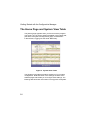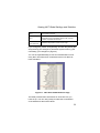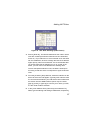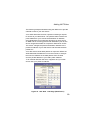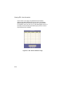
1
ADSL BarricadeTM
4-Port ADSL Router with Built-in
Annex A ADSL Modem
User Guide
February 2004
TABLE OF CONTENTS
Introduction . . . . . . . . . . . . . . . . . . . . . . . . . . . . . . . 1
Features . . . . . . . . . . . . . . . . . . . . . . . . . . . . . . . . . . . . . . . . . . . 1
System Requirements . . . . . . . . . . . . . . . . . . . . . . . . . . . . . . . . 2
Using this Document . . . . . . . . . . . . . . . . . . . . . . . . . . . . . . . . . 2
Notational conventions . . . . . . . . . . . . . . . . . . . . . . . . . . . 2
Typographical conventions . . . . . . . . . . . . . . . . . . . . . . . . 3
Special messages . . . . . . . . . . . . . . . . . . . . . . . . . . . . . . . 3
Getting to Know the ADSL Barricade . . . . . . . . . . 5
Package Contents . . . . . . . . . . . . . . . . . . . . . . . . . . . . . . . . . . . 5
Hardware Description . . . . . . . . . . . . . . . . . . . . . . . . . . . . . . . . . 6
Front Panel . . . . . . . . . . . . . . . . . . . . . . . . . . . . . . . . . . . . 6
Rear Panel . . . . . . . . . . . . . . . . . . . . . . . . . . . . . . . . . . . . 6
Quick Start . . . . . . . . . . . . . . . . . . . . . . . . . . . . . . . . 7
Connecting the Hardware . . . . . . . . . . . . . . . . . . . . . . . . . . . . . . 7
Step 1. Connect the ADSL cable . . . . . . . . . . . . . . . . . . . 8
Step 2. Connect the Ethernet cable . . . . . . . . . . . . . . . . . 9
Step 3. Attach the power connector . . . . . . . . . . . . . . . . . 9
Step 4. Power up your systems . . . . . . . . . . . . . . . . . . . . 9
Configuring Your Computers . . . . . . . . . . . . . . . . . . . . . . . . . . . 9
Before you begin . . . . . . . . . . . . . . . . . . . . . . . . . . . . . . . . 9
Windows® XP . . . . . . . . . . . . . . . . . . . . . . . . . . . . . . . . . 10
Windows 2000 . . . . . . . . . . . . . . . . . . . . . . . . . . . . . . . . 11
Windows Me . . . . . . . . . . . . . . . . . . . . . . . . . . . . . . . . . . 12
Windows 95, 98 . . . . . . . . . . . . . . . . . . . . . . . . . . . . . . . 13
Windows NT 4.0 . . . . . . . . . . . . . . . . . . . . . . . . . . . . . . . 15
Assigning static Internet Information to your PCs . . . . . . 16
Configuring the ADSL Barricade . . . . . . . . . . . . . . . . . . . . . . . 17
Logging into the ADSL Barricade –
Quick Configuration Page . . . . . . . . . . . . . . . . . . . . . . . . 17
Default Router Settings . . . . . . . . . . . . . . . . . . . . . . . . . . 20
i
Table of Contents
Getting Started with the Configuration Manager 23
Accessing the Configuration Manager . . . . . . . . . . . . . . . . . . .
Functional Layout . . . . . . . . . . . . . . . . . . . . . . . . . . . . . . . . . .
Commonly used buttons . . . . . . . . . . . . . . . . . . . . . . . .
The Home Page and System View Table . . . . . . . . . . . . . . . .
Modifying Basic System Information . . . . . . . . . . . . . . . . . . . .
Committing Changes and Rebooting . . . . . . . . . . . . . . . . . . . .
Committing your changes . . . . . . . . . . . . . . . . . . . . . . .
Rebooting the device using Configuration Manager . . .
23
25
25
26
28
30
30
31
Configuring the LAN Ports . . . . . . . . . . . . . . . . . .33
Connecting via Ethernet . . . . . . . . . . . . . . . . . . . . . . . . . . . . . 33
Configuring the LAN Port IP Address . . . . . . . . . . . . . . . . . . . 33
Viewing System IP Addresses
and IP Performance Statistics . . . . . . . . . . . . . . .39
Viewing the ADSL Barricade's IP Addresses . . . . . . . . . . . . . . 39
Viewing IP Performance Statistics . . . . . . . . . . . . . . . . . . . . . . 41
Configuring Dynamic Host Configuration
Protocol . . . . . . . . . . . . . . . . . . . . . . . . . . . . . . . . .43
Overview of DHCP . . . . . . . . . . . . . . . . . . . . . . . . . . . . . . . . . .
What is DHCP? . . . . . . . . . . . . . . . . . . . . . . . . . . . . . . .
Why use DHCP? . . . . . . . . . . . . . . . . . . . . . . . . . . . . . .
ADSL Barricade DHCP modes . . . . . . . . . . . . . . . . . . .
Configuring DHCP Server . . . . . . . . . . . . . . . . . . . . . . . . . . . .
Guidelines for creating DHCP server address pools . . .
Adding DHCP Server Address Pools . . . . . . . . . . . . . . .
Viewing, modifying, and deleting address pools . . . . . .
Excluding IP addresses from a pool . . . . . . . . . . . . . . . .
Viewing current DHCP address assignments . . . . . . . .
Configuring DHCP Relay . . . . . . . . . . . . . . . . . . . . . . . . . . . . .
Setting the DHCP Mode . . . . . . . . . . . . . . . . . . . . . . . . . . . . .
43
43
44
44
45
45
47
50
51
51
52
54
Configuring Network Address Translation . . . . .57
Overview of NAT . . . . . . . . . . . . . . . . . . . . . . . . . . . . . . . . . . . 57
ii
Table of Contents
Viewing NAT Global Settings
and Statistics . . . . . . . . . . . . . . . . . . . . . . . . . . . . . . . . . . . 59
Viewing NAT Rules and Rule Statistics . . . . . . . . . . . . . . . . . . 62
Viewing Current NAT Translations . . . . . . . . . . . . . . . . . . . . . . 63
Adding NAT Rules . . . . . . . . . . . . . . . . . . . . . . . . . . . . . . . . . . 66
The NAPT rule: Translating between private
and public IP addresses . . . . . . . . . . . . . . . . . . . . . . . . . 66
The RDR rule: Allowing external access
to a LAN computer . . . . . . . . . . . . . . . . . . . . . . . . . . . . . 68
The Basic rule: Performing 1:1 translations . . . . . . . . . . 72
The Filter rule: Configuring a BASIC rule
with additional criteria . . . . . . . . . . . . . . . . . . . . . . . . . . . 74
The Bimap rule: Performing two-way translations . . . . . 76
The Pass rule: Allowing specific addresses
to pass through untranslated . . . . . . . . . . . . . . . . . . . . . 78
Configuring DNS Server Addresses . . . . . . . . . . 81
About DNS . . . . . . . . . . . . . . . . . . . . . . . . . . . . . . . . . . . . . . . . 81
Assigning DNS Addresses . . . . . . . . . . . . . . . . . . . . . . . . . . . . 81
Configuring DNS Relay . . . . . . . . . . . . . . . . . . . . . . . . . . . . . . 82
Configuring IP Routes . . . . . . . . . . . . . . . . . . . . . 85
Overview of IP Routes . . . . . . . . . . . . . . . . . . . . . . . . . . . . . . . 85
IP routing versus telephone switching . . . . . . . . . . . . . . 85
Hops and gateways . . . . . . . . . . . . . . . . . . . . . . . . . . . . 86
Using IP routes to define default gateways . . . . . . . . . . 87
Do I need to define IP routes? . . . . . . . . . . . . . . . . . . . . 87
Viewing the IP Routing Table . . . . . . . . . . . . . . . . . . . . . . . . . . 88
Adding IP Routes . . . . . . . . . . . . . . . . . . . . . . . . . . . . . . . . . . . 90
Configuring the Routing Information Protocol . 93
RIP Overview . . . . . . . . . . . . . . . . . . . . . . . . . . . . . . . . . . . . . . 93
When should you configure RIP? . . . . . . . . . . . . . . . . . . 94
Configuring the ADSL Barricade's Interfaces with RIP . . . . . . . 94
Viewing RIP Statistics . . . . . . . . . . . . . . . . . . . . . . . . . . . . . . . . 98
Configuring the ATM Virtual Circuit . . . . . . . . . . 99
iii
Table of Contents
Viewing Your ATM VC . . . . . . . . . . . . . . . . . . . . . . . . . . . . . . . 99
Adding ATM VCs . . . . . . . . . . . . . . . . . . . . . . . . . . . . . . . . . . 101
Modifying ATM VCs . . . . . . . . . . . . . . . . . . . . . . . . . . . . . . . . 102
Configuring PPP Interfaces . . . . . . . . . . . . . . . .105
Viewing Your Current PPP Configuration . . . . . . . . . . . . . . .
Viewing PPP Interface Details . . . . . . . . . . . . . . . . . . . . . . . .
Adding a PPP Interface Definition . . . . . . . . . . . . . . . . . . . . .
Modifying and Deleting PPP Interfaces . . . . . . . . . . . . . . . . .
106
109
112
113
Configuring EOA Interfaces . . . . . . . . . . . . . . . .115
Overview of EOA . . . . . . . . . . . . . . . . . . . . . . . . . . . . . . . . . . 115
Viewing Your EOA Setup . . . . . . . . . . . . . . . . . . . . . . . . . . . . 116
Adding EOA Interfaces . . . . . . . . . . . . . . . . . . . . . . . . . . . . . 118
Configuring IPoA Interfaces . . . . . . . . . . . . . . . .121
Viewing Your IPoA Interface Setup . . . . . . . . . . . . . . . . . . . . 121
Adding IPoA Interfaces . . . . . . . . . . . . . . . . . . . . . . . . . . . . . 123
Configuring Bridging . . . . . . . . . . . . . . . . . . . . .125
Overview of Bridges . . . . . . . . . . . . . . . . . . . . . . . . . . . . . . . .
When to Use the Bridging Feature . . . . . . . . . . . . . . . . . . . .
Defining Bridge Interfaces . . . . . . . . . . . . . . . . . . . . . . . . . . .
Deleting a Bridge Interface . . . . . . . . . . . . . . . . . . . . . . . . . .
125
127
127
129
Configuring Firewall Settings . . . . . . . . . . . . . . .131
Configuring Global Firewall Settings . . . . . . . . . . . . . . . . . . . 131
Managing the Black List . . . . . . . . . . . . . . . . . . . . . . . . . . . . . 134
Configuring IP Filters and Blocked Protocols .135
Configuring IP Filters . . . . . . . . . . . . . . . . . . . . . . . . . . . . . . .
Viewing Your IP Filter Configuration . . . . . . . . . . . . . .
Configuring IP Filter Global Settings . . . . . . . . . . . . . .
Creating IP Filter Rules . . . . . . . . . . . . . . . . . . . . . . . .
IP filter rule examples . . . . . . . . . . . . . . . . . . . . . . . . . .
Viewing IP Filter Statistics . . . . . . . . . . . . . . . . . . . . . .
Managing Current IP Filter Sessions . . . . . . . . . . . . . .
iv
135
136
137
138
145
147
148
Table of Contents
Blocked Protocols . . . . . . . . . . . . . . . . . . . . . . . . . . . . . . . . . . 149
Viewing DSL Line Information . . . . . . . . . . . . . . 153
Administrative Tasks . . . . . . . . . . . . . . . . . . . . . 157
Configuring User Names and Passwords . . . . . . . . . . . . . . . . 157
Changing Login Passwords . . . . . . . . . . . . . . . . . . . . . 157
Viewing System Alarms . . . . . . . . . . . . . . . . . . . . . . . . . . . . . 159
Viewing the Alarm Table . . . . . . . . . . . . . . . . . . . . . . . . 159
Upgrading the Software . . . . . . . . . . . . . . . . . . . . . . . . . . . . . 160
Using Diagnostics . . . . . . . . . . . . . . . . . . . . . . . . . . . . . . . . . . 161
Modifying Port Settings . . . . . . . . . . . . . . . . . . . . . . . . . . . . . . 163
Overview of IP port numbers . . . . . . . . . . . . . . . . . . . . 163
Modifying the ADSL Barricade’s port numbers . . . . . . . 164
Appendix A . . . . . . . . . . . . . . . . . . . . . . . . . . . . . 167
IP Addresses . . . . . . . . . . . . . . . . . . . . . . . . . . . . . . . . . . . . . 167
Structure of an IP address . . . . . . . . . . . . . . . . . . . . . . 167
Network classes . . . . . . . . . . . . . . . . . . . . . . . . . . . . . . . . . . . 169
Subnet masks . . . . . . . . . . . . . . . . . . . . . . . . . . . . . . . . . . . . . 170
Appendix B . . . . . . . . . . . . . . . . . . . . . . . . . . . . . 173
Binary Numbers . . . . . . . . . . . . . . . . . . . . . . . . . . . . . . . . . . . 173
Bits and bytes . . . . . . . . . . . . . . . . . . . . . . . . . . . . . . . . 174
Troubleshooting . . . . . . . . . . . . . . . . . . . . . . . . . 175
Technical Specifications . . . . . . . . . . . . . . . . . . 181
Terminology . . . . . . . . . . . . . . . . . . . . . . . . . . . . 185
Compliances . . . . . . . . . . . . . . . . . . . . . . . . . . . . . . i
Legal Information and Contacts . . . . . . . . . . . . . vii
v
INTRODUCTION
Congratulations on becoming the owner of the ADSL Barricade,
a 4-port ADSL Router with built-in ADSL Modem. Your LAN (Local
Area Network) will now be able to access the Internet using your
high-speed ADSL connection. This User Guide will show you how
to set up the ADSL Barricade, and how to customize its
configuration to get the most out of your new product.
Features
•
External ADSL modem for high-speed Internet access.
•
10/100Base-T Ethernet router to provide Internet connectivity
to all computers on your LAN.
•
Network address translation (NAT), Firewall, and IP filtering
functions to provide security for your LAN.
•
Network configuration through DHCP Server and DHCP Relay.
•
Services including IP route and DNS configuration, RIP,
and IP and DSL performance monitoring.
•
Configuration program you access via an HTML browser.
1
Introduction
System Requirements
In order to use the ADSL Barricade, you must have the following:
•
ADSL service up and running on your telephone line,
with at least one public Internet address for your LAN.
•
One or more computers each containing an Ethernet
10/100 Base-T network interface card (NIC).
•
An Ethernet hub/switch, if you are connecting the device
to more than one computer on an Ethernet network.
•
For system configuration using the supplied web-based
program: a web browser such as Internet Explorer V5.0
or later, or Netscape V6.1 or later.
Using this Document
Notational conventions
2
•
Acronyms are defined the first time they appear in the text
and in the Terminology.
•
For brevity, the ADSL Barricade is referred to as the device.
•
The terms LAN and network are used interchangeably to refer
to a group of Ethernet-connected computers at one site.
Using this Document
Typographical conventions
•
Italics are used to identify terms that are defined
in the Terminology.
•
Square brackets are used for items you select from
menus and drop-down lists.
Special messages
This document uses the following statement to call your attention
to specific instructions or explanations.
Note: Provides clarifying or non-essential information
on the current topic.
Definition: Explains terms or acronyms that may be unfamiliar
to many readers. These terms are also included in the Terminology.
Warning: Provides messages of high importance, including
messages relating to personal safety or system integrity.
3
GETTING TO KNOW THE
ADSL BARRICADE
Package Contents
•
One ADSL Barricade.
•
One Power adapter.
•
One RJ-45 Ethernet cable.
•
One RJ-11 Standard phone/DSL line cable.
•
Installation utility and Documentation CD.
•
Quick Installation Guide.
5
Getting to Know the ADSL Barricade
Hardware Description
Front Panel
LED Label
Power
Color Status
Green
Link
TX/RX
Ethernet
1 2 3 4
Green
Green
Green Steady Power On
ADSL line
is trained.
DSL
Link
Transmitting/
Receiving
Green Blink
Training
TX/RX
N/A
Green / 100 Mbps
Yellow / 10 Mbps
Transmitting/
Receiving
Yellow Steady N/A
N/A
N/A
Link
Yellow Blink
N/A
N/A
N/A
Transmitting/
Receiving
OFF
Power Off
No Connection No TX/RX
No Connection
(*Alarm LED is optional, and for manufactory only*)
Table 1. Front Panel and LEDs
Rear Panel
Rear Panel Connector
Description
Power Supply
12V, 1.2A
Reset and Restore Factory Defaults Button
If depressed for 1-2 seconds:
reset.
If depressed for 5 seconds or
more: reset to factory default.
DSL Port
RJ-11 phone connector
Ethernet Port
Four 10/100M BASE-T RJ-45
connectors
Table 2. Rear Panel Connections
6
QUICK START
This Quick Start provides basic instructions for connecting
the ADSL Barricade to a computer or LAN and to the Internet.
•
Connecting the Hardware describes how to set up the hardware.
•
Configuring Your Computers describes how to configure
Internet properties on your computer(s).
•
Configuring the ADSL Barricade shows you how to configure
basic settings on the ADSL Barricade to get your LAN
connected to the Internet.
This Quick Start assumes that you have already established
an ADSL service with your Internet service provider (ISP).
These instructions provide a basic configuration that should
be compatible with your home or small office network setup.
Refer to the subsequent chapters for additional configuration
instructions.
Connecting the Hardware
You connect the device to the wall phone jack, the power outlet,
and your computer or network.
Warning:
Before you begin, turn the power off for all devices.
These include your computer(s), your LAN hub/
switch (if applicable), and the ADSL Barricade.
7
Quick Start
Wall Jack
ADSL Barricade
AC adapter
To a hub: use crossover cable to uplink
port or straight cable
to standard port
or
To a PC: use a
cross-over cable
Hub/switch (for local
area network)
Stand-alone computer
Networked Computers
Figure 1. Overview of Hardware Connections
Step 1. Connect the ADSL cable
Connect one end of the provided phone cable (RJ-11) to the port
labeled ADSL on the Rear Panel of the device. Connect the other
end to your wall phone jack.
You can attach a telephone line to the device. This is helpful
when the ADSL line uses the only convenient wall phone jack.
If desired, connect the telephone cable to the port labeled Phone.
8
Warning:
Although you use the same type of cable, the ADSL
and Phone ports are not interchangeable. Do not
route the ADSL connection through the Phone port.
Note:
ADSL splitters/microfilters are included with some
models.
Configuring Your Computers
Step 2. Connect the Ethernet cable
If you are connecting a LAN to the ADSL Barricade, attach one end
of a provided Ethernet cable to a regular hub port and the other to
the Ethernet port on the ADSL Barricade. If you are using the ADSL
Barricade with a single computer and no hub, you must use an
Ethernet cable to attach the PC directly to the device. The cable is
wired differently than the cable you would use to connect to a hub.
Step 3. Attach the power connector
Connect the AC power adapter to the Power connector on the back
of the device and plug in the adapter to a wall outlet or power strip.
Step 4. Power up your systems
Turn on and boot up your computer(s) and any LAN devices
such as hubs or switches.
Configuring Your Computers
This section provides instructions for configuring the Internet
settings on your computers to work with the ADSL Barricade.
Before you begin
By default, the ADSL Barricade automatically assigns all required
Internet settings to your PCs. You need only to configure the PCs
to accept the information when it is assigned.
Note:
In some cases, you may want to assign Internet
information manually to some or all of your computers
rather than allow the ADSL Barricade to do so. See
Assigning static Internet Information to your PCs on
page 16 for instructions.
9
Quick Start
If you have connected your PC of LAN via Ethernet to the ADSL
Barricade, follow the instructions that correspond to the operating
system installed on your PC.
Windows® XP
1. In the Windows task bar, click the [Start] button, and then
click [Control Panel].
2. Double-click the [Network Connections] icon.
3. In the [LAN or High-Speed Internet] window, right-click on
the icon corresponding to your network interface card (NIC)
and select [Properties]. (Often, this icon is labeled [Local
Area Connection].) The [Local Area Connection] dialog
box displays a list of currently installed network items.
4. Ensure that the check box to the left of the item labeled
[Internet Protocol (TCP/IP)] is checked, and click [Properties].
5. In the [Internet Protocol (TCP/IP) Properties] dialog box, click
the radio button labeled [Obtain an IP address automatically].
Also click the radio button labeled [Obtain DNS server address
automatically].
6. Click [OK] twice to confirm your changes, and close
the Control Panel.
10
Configuring Your Computers
Windows 2000
First, check for the IP protocol and, if necessary, install it.
1. In the Windows task bar, click the [Start] button,
point to [Settings], and then click [Control Panel].
2. Double-click the [Network and Dial-up Connections] icon.
3. In the [Network and Dial-up Connections] window, right-click the
[Local Area Connection] icon, and then select [Properties]. The
[Local Area Connection Properties] dialog box displays a list
of currently installed network components. If the list includes
[Internet Protocol (TCP/IP)], then the protocol has already
been enabled. Skip to Step 10.
4. If [Internet Protocol (TCP/IP)] does not appear as an installed
component, click [Install...].
5. In the [Select Network Component Type] dialog box, select
[Protocol], and then click [Add…].
6. Select [Internet Protocol (TCP/IP)] in the [Network Protocols]
list, and then click [OK]. You may be prompted to install files
from your Windows 2000 installation CD or other media.
Follow the instructions to install the files.
7. If prompted, click [OK] to restart your computer with the new
settings. Next, configure the PCs to accept IP information
assigned by the ADSL Barricade.
8. In the [Control Panel], double-click the [Network and Dial-up
Connections] icon.
9. In the [Network and Dial-up Connections] window, right-click
the [Local Area Connection] icon, and then select [Properties].
11
Quick Start
10. In the [Local Area Connection Properties] dialog box, select
[Internet Protocol (TCP/IP)], and then click [Properties].
11. In the [Internet Protocol (TCP/IP) Properties] dialog box, click
the radio button labeled [Obtain an IP address automatically].
Also click the radio button labeled [Obtain DNS server address
automatically].
12. Click [OK] twice to confirm and save your changes,
and then close the Control Panel.
Windows Me
1. In the Windows task bar, click the [Start] button,
point to [Settings], and then click [Control Panel].
2. Double-click the [Network and Dial-up Connections] icon.
3. In the [Network and Dial-up Connections] window, right-click
the [Network] icon, and then select [Properties]. The [Network
Properties] dialog box displays a list of currently installed
network components. If the list includes Internet Protocol
(TCP/IP), then the protocol has already been enabled.
Skip to Step 11.
4. If [Internet Protocol (TCP/IP)] does not appear as an installed
component, click [Add…].
5. In the [Select Network Component Type] dialog
box, select [Protocol], and then click [Add…].
6. Select [Microsoft] in the [Manufacturers] box.
7. Select [Internet Protocol (TCP/IP)] in the [Network Protocols]
list, and then click [OK]. You may be prompted to install files
from your Windows Me installation CD or other media.
Follow the instructions to install the files.
12
Configuring Your Computers
8. If prompted, click [OK] to restart your computer with the new
settings. Next, configure the PCs to accept IP information
assigned by the ADSL Barricade.
9. In the Control Panel, double-click the [Network and Dial-up
Connections] icon.
10. In the [Network and Dial-up Connections] window, right-click
the [Network] icon, and then select [Properties].
11. In the [Network Properties] dialog box, select [TCP/IP],
and then click [Properties].
12. In the [TCP/IP Settings] dialog box, click the radio button
labeled [Server assigned IP address]. Also click the radio
button labeled [Server assigned name server address].
13. Click [OK] twice to confirm and save your changes,
and then close the Control Panel.
Windows 95, 98
First, check for the IP protocol and, if necessary, install it.
1. In the Windows task bar, click the [Start] button,
point to [Settings], and then click [Control Panel].
2. Double-click the [Network] icon. The [Network] dialog box
displays a list of currently installed network components.
If the list includes [TCP/IP], then the protocol has already
been enabled. Skip to Step 9.
3. If [TCP/IP] does not appear as an installed component, click
[Add…]. The [Select Network Component Type] dialog box
appears.
13
Quick Start
4. Select [Protocol], and then click [Add...]. The [Select Network
Protocol] dialog box appears.
5. Click on [Microsoft] in the [Manufacturers] list box, and then click
[TCP/IP] in the [Network Protocols] list box.
6. Click [OK] to return to the [Network] dialog box, and then click
[OK] again. You may be prompted to install files from your
Windows 95/98 installation CD. Follow the instructions
to install the files.
7. Click [OK] to restart the PC and complete the TCP/IP installation.
Next, configure the PCs to accept IP information assigned by the
ADSL Barricade.
8. Open the [Control Panel] window, and then click
the [Network] icon.
9. Select the network component labeled [TCP/IP], and then
click [Properties]. If you have multiple TCP/IP listings, select
the listing associated with your network card or adapter.
10. In the [TCP/IP Properties] dialog box, click the [IP Address] tab.
11. Click the radio button labeled [Obtain an IP address
automatically].
12. Click the [DNS Configuration] tab, and then click the
radio button labeled [Obtain an IP address automatically].
13. Click [OK] twice to confirm and save your changes.
You will be prompted to restart Windows.
14. Click [Yes].
14
Configuring Your Computers
Windows NT 4.0
First, check for the IP protocol and, if necessary, install it.
1. In the Windows NT task bar, click the [Start] button,
point to [Settings], then click [Control Panel].
2. In the [Control Panel] window, double-click the [Network] icon.
3. In the [Network] dialog box, click the [Protocols] tab. The
[Protocols] tab displays a list of currently installed network
protocols. If the list includes [TCP/IP], then the protocol
has already been enabled. Skip to Step 9.
4. If [TCP/IP] does not display as an installed component,
click [Add...].
5. In the [Select Network Protocol] dialog box, select [TCP/IP],
and then click [OK]. You may be prompted to install files from
your Windows NT 4.0 installation CD or other media. Follow
the instructions to install the files. After all files are installed,
a window appears to inform you that a TCP/IP service called
DHCP can be set up to dynamically assign IP information.
6. Click [Yes] to continue, and then click [OK] if prompted to restart
your computer. Next, configure the PCs to accept IP information
assigned by the ADSL Barricade.
7. Open the [Control Panel] window, and then double-click
the [Network] icon.
8. In the [Network] dialog box, click the [Protocols] tab.
9. In the [Protocols] tab, select [TCP/IP], then click [Properties].
10. In the [Microsoft TCP/IP Properties] dialog box, click the radio
button labeled [Obtain an IP address from a DHCP server].
11. Click [OK] twice to confirm and save your changes, and then
close the [Control Panel].
15
Quick Start
Assigning static Internet Information to your PCs
In some cases, you may want to assign Internet information to
some or all of your PCs directly (often called statically), rather
than allowing the ADSL Barricade to assign it. This option may
be desirable (but not required) if:
•
You have obtained one or more public IP addresses that
you want to associate with specific computers (for example,
if you are using a computer as a public web server).
•
You maintain different subnets on your LAN (subnets are
described in IP Addresses, Network Masks, and Subnets).
Before you begin, be sure to have the following information on hand
(or contact your ISP if you do not know it):
•
The IP address and subnet mask you will assign to each
PC which will be assigned static IP information.
•
The IP address of the default gateway for your LAN. In most
cases, this is the address assigned to the LAN port on the ADSL
Barricade. By default, the LAN port is assigned this IP address:
[192.168.1.1.] (You can change this number, or another number
can be assigned by your ISP.) See Configuring the LAN Ports
on page 33 for more information.
•
The IP address of your ISP's Domain Name System
(DNS) server.
On each PC you will assign static information, follow the
instructions on pages 11 through 16 specific to the IP protocol.
Once it is installed, continue to follow the instructions for
displaying each of the Internet Protocol (TCP/IP) properties.
Instead of enabling dynamic assignment of the IP addresses for
the computer, the DNS server, and the default gateway, click the
radio buttons that enable you to enter the information manually.
16
Configuring the ADSL Barricade
Note:
Your PCs must have IP addresses that place them
in the same subnet as the ADSL Barricade's LAN port.
If you manually assign IP information to all your LAN
PCs, you can follow the instructions in Configuring
the LAN Ports to change the LAN port IP address
accordingly.
Configuring the ADSL Barricade
This section provides you instructions on how to log into the
program of the ADSL Barricade and how to configure basic
settings for your Internet connection. Your ISP should provide
you with the necessary information to complete this step.
Logging into the ADSL Barricade –
Quick Configuration Page
The ADSL Barricade provides a preinstalled software program
called Configuration Manager which enables you to configure the
operation of the device via your Web browser. The settings that
you most likely need to change before using the device
are grouped onto one single [Quick Configuration] page.
Follow these instructions to configure the device settings.
1. At any PC connected to the ADSL Barricade via Ethernet, open
your Web browser, and type the following URL in the address/
location box: 192.168.1.1/setup. Username/Password:
smc/smcadmin.
2. When you press [Enter], the page shown in Figure 2 should
appear (see section Troubleshooting on page 175, if you
receive an error message or if the page does not appear).
17
Quick Start
Figure 2. Quick Configuration Page in Configuration
Manager
The fields are described in the following table. Work with your
ISP to determine which settings you need to change.
Field
Description
ATM Interface:
This setting allows you to select the ATM interface you want to
use (usually [atm-0]). Your system may be configured with more
than one ATM interface if you are using different types of services
with your ISP.
Operation Mode:
This setting enables or disables the ADSL Barricade.
When set to [No], the device cannot be used to provide Internet
connectivity for your network. Set it to [Enabled ], if necessary.
Encapsulation:
This setting determines the type of data link your ISP uses
to communicate with your ADSL Barricade. Contact them
to determine the appropriate setting.
VPI:
VCI:
These values are provided by your ISP and determine the unique
path that your connection uses to communicate with your ISP.
General Settings
18
Configuring the ADSL Barricade
Bridge:
You may select [Enabled] or [Disabled] to set the bridging between
the ADSL Barricade and your ISP. Your ISP may also refer to this
as RFC 1483 or Ethernet over ATM.
IGMP:
You may select [Enabled] or [Disabled] to set the Internet Group
Management Protocol, which some ISPs use to perform remote
configuration of your device.
IP Address:
Subnet Mask:
If your ISP has assigned a public IP address to your LAN, enter the
address and the associated subnet mask in the provided boxes.
(Note: In some configurations, the public IP address should be
entered on your PC rather than on the ADSL Barricade; please
check with your ISP.)
Primary DNS
Server:
Secondary DNS
Server:
Enter the Primary and Secondary DNS server addresses
provided by your ISP.
Username:
Password:
Enter the Username and the Password you use to log in to your
ISP. (Note: This is not the same as the user name and password
you have used to log in to Configuration Manager.)
DNS
PPP
3. When you have finished customizing these settings, click
[Submit]. The settings are now effective. However, if you
reboot or if the power is disconnected, your settings will
be lost. In Step 4, you save the changes to the permanent
memory.
4. Click the [Admin] tab that appears in the upper right corner
of the page, and then click [Commit & Reboot] in the task bar.
5. Click [Commit]. A page will appear briefly to confirm your
changes, and then you will be returned to the [Commit &
Reboot] page.
You can click [Delete] to remove all existing [Quick Configuration]
settings and return to the default values.
19
Quick Start
You have now finished customizing the basic settings. Read
the following section in order to determine whether you need
to change additional settings.
Default Router Settings
In addition to handling the DSL connection to your ISP, the ADSL
Barricade can provide a variety of services to your network. The
device is preconfigured with default settings for use with a typical
home or small office network.
Table 4 lists some of the most important default settings; these and
other features are fully described in the subsequent sections. If you
are familiar with network configuration, review the settings in Table 4
and check whether they meet the needs of your network. Follow the
instructions and change them if necessary. If you are unfamiliar
with these settings, try to use the device without modification,
or contact your ISP for assistance.
Before modifying any settings, review the Getting Started section
with the Configuration Manager. We strongly recommend that
you contact your ISP prior to changing the default configuration.
Option
Default Setting
Explanation/Instructions
DHCP
DHCP server enabled
with the following pool
of addresses: 192.168.1.3
through 192.168.1.34
The ADSL Barricade maintains
a pool of private IP addresses for
dynamic assignment to your LAN
computers. To use this service,
you must have set up your
computers to accept IP
information dynamically, as
described in the Quick Start.
See Configuring Dynamic Host
Configuration Protocol on page
43 for an explanation of the
DHCP service.
20
Configuring the ADSL Barricade
NAT
NAT rule enabled
Your computers’ private IP
addresses (see DHCP above)
will be translated to your public
IP address whenever they access
the Internet. See Configuring the
LAN Ports on page 33 for a
description of the NAT service.
Assigned static
IP address:
192.168.1.1
Subnet mask:
255.255.255.0
This is the IP address of the LAN
port on the device. The LAN port
connects the device to your
Ethernet network. Typically,
you will not need to change
this address. See Configuring
the LAN Ports on page 33 for
instructions.
(Network Address
Translation)
LAN Port IP Address
Table 3. Default Settings Summary
21
GETTING STARTED WITH THE
CONFIGURATION MANAGER
The ADSL Barricade includes a preinstalled program called
Configuration Manager, which provides an interface to the
software installed on the device. It enables you to configure
the device settings to meet the needs of your network. You
access it through your web browser from any PC connected
to the ADSL Barricade via the LAN ports.
This section describes how to use the Configuration Manager.
Accessing the Configuration Manager
The Configuration Manager program is preinstalled in the ADSL
Barricade memory. To access the program, you need the following:
•
A PC or laptop connected to the LAN port on the device
as described in the Quick Start section.
•
A web browser installed on the PC. The program is designed
to work best with Microsoft Internet Explorer® version 5.0,
Netscape Navigator® version 6.1, or later versions.
You can access the program from any computer connected
to the ADSL Barricade via the LAN ports.
1. From a LAN computer, open your web browser, type the
following URL in the web address (or location) box, and
press [Enter: http://192.168.1.1].
These are the predefined IP addresses for the LAN
on the ADSL Barricade. A login screen appears, as shown
in Figure 3.
23
Getting Started with the Configuration Manager
Figure 3. Login Screen
2. Enter your [User Name] and [Password], and then click [OK].
The first time you log into the program, use these default values:
Default User Name : smc
Default Password : smcadmin
Note:
You can change the password at any time
(See Configuring User Names and Passwords on
page 157 for instructions).
The [System View] page on the [Home] tab appears
each time you log into the program (shown in Figure 4).
24
Functional Layout
Functional Layout
Configuration Manager tasks are grouped into several categories,
which can be accessed by clicking the tabs at the top of each page.
Each tab displays the available tasks in a horizontal menu at the
top of the page. You can click on these menu items and display
the specific configuration options.
A separate page appears for each task in the task bar. The left-most
task appears by default when you click on a new tab. The same
task may appear in more than one tab, when appropriate. For
example, the [Lan Config] task appears in both the [LAN]
tab and the [Routing] tab.
Commonly used buttons
The following buttons are used throughout the application.
Button
Function
Submit
This button stores in the temporary system memory any changes
you have made on the current page. See Committing your changes
on page 30 for instructions on how to store changes permanently.
Refresh
This button displays the current page with updated statistics
or settings.
Clear
On pages that display accumulated statistics, this button resets
the statistics to their initial values.
Help
This button launches the online help for the current topic in a separate
browser window. Help is available from any main topic page.
25
Getting Started with the Configuration Manager
The Home Page and System View Table
The [Home] page appears when you first access the program.
This page is one of the two options available in the [Home] tab;
(the other is the [Quick Configuration] page, as described
in Quick Start, Logging into the ADSL Barricade).
Figure 4. System View Table
The [System View] table provides a snapshot of your system
configuration. Note that some of the settings are links to the
software pages that enable you to configure those settings. The
following table describes each section of the [System View] table.
26
The Home Page and System View Table
Table
Heading
Description
Device
This table displays basic information about the ADSL Barricade
hardware and software versions, the system uptime (since
the last reboot), and the preconfigured operating mode.
DSL
This table displays the operational status, version, and performance
statistics for the DSL line. You can check DSL in the table or display
the [WAN] tab to view additional DSL settings, which are described
in Configuring EOA Interfaces.
WAN
Interfaces
This table displays the software name(s) and various settings for
the device interface(s) that communicates with your ISP via DSL.
Even if you only have one physical DSL port, multiple softwaredefined interfaces can be configured to use it. See the ATM VC,
PPP, EOA, and IPoA chapters for more information about the WAN
interfaces defined on your system. For each interface, a [Lower
Interface] name, such as [aal5-0], should appear. You can click
on the [Lower Interface] name to view or change the ATM VC
settings that this interface uses.
LAN
Interface
This table displays the software names and various settings for the
device interfaces that communicate directly with your network. These
typically include an [Ethernet Interface] named [eth-0], and may
include a [USB Interface] named [usb-0]. For information on how
to modify properties of these interfaces, see Configuring the LAN
Ports on page 33.
27
Getting Started with the Configuration Manager
Services
Summary
This table displays the status of various services that the ADSL
Barricade performs to help you manage your network. A green
check mark indicates that the service is active and a red X
indicates that it is inactive.
[NAT] : to translate private IP addresses to your public IP address
(Configuring Network Address Translation).
[IP Filter] : to set up the filtering rules that accept or deny incoming
or outgoing data (Configuring IP Filters and Blocking Protocols).
[RIP] : to enable router-to-router communication (Configuring the
Routing Information Protocol).
[DHCP Relay] : to enable dynamic assignment of IP information from
your ISP to your computers (Configuring Dynamic Host Configuration
Protocol).
[DHCP Client] : to enable dynamic assignment of IP information from
your ISP or another computer on your network to the device’s LAN
port (Configuring the LAN Ports).
[DHCP Server]: to enable dynamic assignment of IP information from
the device’s built-in DHCP server to your LAN computers (Configuring
Dynamic Host Configuration).
[IGMP] : to enable message forwarding from external sources such
as your ISP, based on Internet Group Management Protocol (not
configurable).
Modifying Basic System Information
You can modify the basic system information, which includes the
system date and time, the names assigned to the ADSL Barricade
and the network domain in which it exists.
Note:
Changing the ADSL Barricade date and time does not
affect the date and time on your PCs.
Follow these instructions to change the basic system information.
28
Modifying Basic System Information
1. At the bottom of the [Home] page, click [Modify].
The [System – Modify] page appears in a separate
browser window.
Figure 5. System - Modify Page
2. Modify the fields on this page as required.
The following table describes each field:
Option
Description
Date:
Time:
These fields initially appear dimmed. To modify the date and time,
click the respective check boxes and select the appropriate values
from the drop-down lists. The time appears in military format.
Time Zone:
You can select your time zone from the drop-down list, and then
click the appropriate radio button to indicate whether Daylight
Savings Time is currently in effect. After you initially set the time,
turning DST On or Off will adjust the current displayed time by one
hour in the appropriate direction. You must remember to change
the DST option each spring and fall as it will not change
automatically.
DST:
(Daylight
Savings
Time)
29
Getting Started with the Configuration Manager
Host Name:
You can use this field to specify an easy-to-remember name
for the ADSL Barricade. The next time you want to access the
Configuration Manager, you can type this name in the location box
in your Web browser, instead of typing the digital IP address. For
example, if you have entered myrouter in this field (and have left
the Domain Name field blank), then you can type the following
in your Web browser to access the Configuration Manager:
http://myrouter.
Note: This will only work if you are using the ADSL Barricade’s
DNS relay feature. This feature is automatically enabled when
the DNS server address configured on your PCs is also the address
assigned to the LAN port on the ADSL Barricade. See Configuring
DNS Server Addresses on page 81 for more information.
Domain
Name:
You can use this field to specify an Internet domain name for the
ADSL Barricade. The next time you access Configuration Manager,
you can type the domain name and the device name (see the Name
field above) in your Web browser. For example, if you have entered
myrouter in the [Name] field and mydomain.com in the [Domain
Name] field, then you can type the following in your Web browser
to access the Configuration Manager: http://myrouter.mydomain.com
3. When you have finished modifying the settings, click [Submit].
Then click [Close] to return to the [System View] page.
4. To save your changes to the permanent memory, click the
[Admin] tab, and then click [Commit & Reboot] in the task bar.
5. Click [Commit].
Committing Changes and Rebooting
Committing your changes
Whenever you use Configuration Manager to change system
settings, the changes are initially placed in a temporary storage
called random access memory or RAM. Your changes become
effective when you submit them, but will be lost if the device
is reset or turned off.
30
Committing Changes and Rebooting
You can commit changes to save them permanently to a flash
memory.
Note:
Submitting changes activates them immediately, but
saves them only until the device is reset or powered
down. Committing changes saves them permanently.
Follow these steps to commit changes.
1. Click the [Admin] tab, and then click [Commit & Reboot]
in the task bar. The [Commit & Reboot] page appears.
Figure 6. Commit & Reboot Page
2. Click [Commit]. Disregard the selection in the [Reboot Mode:]
drop-down list; it does not affect the commit process. These
changes are saved to a permanent storage. The previous
settings are copied to a backup storage so that they can
be recalled if your new settings do not work properly
(see the below rebooting instructions).
Rebooting the device using Configuration Manager
To reboot the device, display the [Commit & Reboot] page, select
the appropriate [Reboot Mode:] from the drop-down list, and then
click [Reboot].
You have three options when rebooting.
31
Getting Started with the Configuration Manager
Option
This option is to reboot the device using the current settings
in the permanent memory, including any changes you have
just committed.
Reboot from Backup
Configuration
This option is to reboot the device using settings stored
in the backup memory. These are the settings that were
effective before you committed new settings in the current
session.
Reboot from Default
Configuration
This option is to reboot the device to the default settings
provided by your ISP or the manufacturer. Choosing this
option erases any custom settings.
Warning:
32
Description
Reboot from Last
Configuration
Do not reboot the device using the [Reset] button
on the Rear Panel of the ADSL Barricade to activate
new changes. This button resets the device settings
to the factory default values. Any custom settings
will be lost.
CONFIGURING THE
LAN PORTS
This section describes how to configure IP properties for the
interfaces on the ADSL Barricade that communicate with your
LAN computers.
Connecting via Ethernet
If you are using the ADSL Barricade with multiple PCs on your LAN,
you must connect the LAN via an Ethernet hub to the device's LAN
port, called [eth-0].
If you are using a single PC with the ADSL Barricade, you can
connect the PC directly to the LAN port using an Ethernet cable.
You must assign a unique IP address to each device port that
you use.
Configuring the LAN Port IP Address
The LAN IP address identifies the LAN port ([eth-0]) as a node
on your network; that is, its IP address must be in the same subnet
as the PCs on your LAN.
Definition:
A network node can be thought of as any interface
where a device connects to the network, such as
the ADSL Barricade's LAN port and the network
interface cards on your PCs. See IP Addresses,
Network Masks, and Subnets for an explanation
of subnets.
You can change the default to reflect the set of IP addresses
that you want to use with your network.
33
Configuring the LAN Ports
If your network uses a DHCP server (other than the ADSL
Barricade) to assign IP addresses, you can configure the
device to accept and use a LAN IP address assigned by that
server. Similarly, if your ISP performs DHCP serving for your
network, you can configure the device to accept an IP address
assigned from the ISP's server. In this mode, the ADSL Barricade
is considered as a DHCP client of your DHCP (or ISP's) server.
Note:
The ADSL Barricade itself can function as a DHCP
server for your LAN computers, as described in
Configuring Dynamic Host Configuration Protocol,
but not for its own LAN port.
Follow the following steps to change the default LAN IP address
or to configure the LAN port as a DHCP client:
1. Log into Configuration Manager and then click the [LAN] tab.
The [LAN Configuration] page appears.
Figure 7. LAN Configuration Page
34
Configuring the LAN Port IP Address
The LAN Configuration table displays the following settings:
Setting
Description
System Mode:
This setting is preconfigured for your device, such as [Routing
mode], [Bridging mode], or both modes simultaneously.
This setting is not user-configurable.
Get LAN
Address:
This setting provides options for how the device’s LAN port
is assigned an IP address:
[Manual] indicates that you will be assigning a static IP address,
which you can enter in the fields below.
[External DHCP Server] indicates that your ISP will be assigning
an IP address from their own DHCP server to the port, dynamically
each time you log on.
[Internal DHCP Server] indicates that you have a DHCP server
device on your network that will assign an address to the port.
If you choose either the internal or external server option, the
LAN port is called a DHCP client of the server.
Note: The public IP address assigned to you by your ISP is not
your LAN IP address. The public IP address identifies the WAN
(ADSL) port on your ADSL Barricade to the Internet.
LAN
The IP address and Network Mask for the port. See IP Addresses,
IP Address:
Network Masks, and Subnets for and overview of IP addresses
LAN
and masks.
Network Mask:
2. Enter an IP address and mask in the fields provided and choose
[Disabled] in the [Use DHCP] field, or enable either a remote
or local DHCP server. Keep these points in mind:
•
Manually specifying an address:
If you are using routing services on your LAN such as DHCP
and NAT, you will want to assign a fixed LAN IP address and
mask. This ensures that your LAN computers have a fixed
address that they use to communicate with the device.
The IP address you assign must be in the same subnet as
your LAN computers that connect to this port (that is, the
network ID portion of their IP addresses and their subnet
35
Configuring the LAN Ports
masks must be the same). See IP Addresses, Network
Masks, and Subnets for an explanation of IP addresses
and network masks.
If you change the LAN IP address, you may need to
update the DHCP configuration so that the addresses
that the DHCP server dynamically assigns to your
computers are on the same subnet as the new LAN IP
address.
See Configuring Dynamic Host Configuration Protocol
on page 43 for instructions on changing the pool of
dynamically assigned addresses.
•
Enabling DHCP:
If you choose to have the LAN port be a DHCP client
of an internal or external server, the [LAN Network Mask]
field will be dimmed and made unavailable for entry. The
[LAN IP Address] field will remain editable, however. The
address that you specify here will be used as a request
to the DHCP server. This is referred to as a Configured IP
Address in the program. If the configured IP address
is not available from the DHCP server, then the system
will accept another assigned address. Even after another
number is assigned, the same configured IP address will
continue to display in this field.
3. Click [Submit].
36
•
If you changed the LAN IP address while working from
a PC that is connected to the device via Ethernet, then your
connection will be terminated.
•
If you enabled the DHCP service, the ADSL Barricade will
initiate a request for an IP address from your LAN's DHCP
server. If a different IP address is assigned than the one that
Configuring the LAN Port IP Address
was previously configured, your current connection will be
terminated.
4. Reconfigure your PCs, if necessary, so that their IP addresses
place them in the same subnet as the new IP address of the
LAN port. See Quick Start, Configuring Your Computers on
page 9 for instructions.
5. Log into [Configuration Manager] by typing the new IP
address in your Web browser's address/location box.
6. If the new settings work properly, click the [Admin]
tab, and then click [Commit & Reboot] in the task bar.
7. Click [Commit] to save your changes to the permanent
memory.
37
VIEWING SYSTEM IP
ADDRESSES AND IP
PERFORMANCE STATISTICS
The interface on the ADSL Barricade that communicates with other
network and Internet devices are identified by unique Internet
protocol (IP) addresses. You can use the Configuration Manager
to view the list of IP addresses that your device uses, and to view
other system and network performance data. See IP Addresses,
Network Masks, and Subnets for a description of IP addresses
and masks.
Viewing the ADSL Barricade's IP Addresses
To view the ADSL Barricade's IP addresses, click the [Routing] tab,
and then click [IP Address] in the task bar. The [IP Address Table]
page appears:
Figure 8. IP Address Table Page
The table lists the [IP address], the network masks ([Netmask]),
and the interface names ([IF Name]) for each of its IP-enabled
interfaces.
39
Viewing System IP Addresses and IP Performance Statistics
The listed IP addresses may include:
•
The IP address of the device's LAN (Ethernet) port, called
[eth-0]. See Configuring the LAN Ports on page 33 for
instructions on configuring this address.
•
The IP address of the WAN (ADSL line) interface, which your
ISP and other external devices use to identify your network.
It may be identified in the [Configuration Manager] by the names
[ppp-0], [eoa-0], or [ipoa-0], depending on the protocol your
device uses to communicate with your ISP. Your ISP may
assign the same address each time, or it may change
each time you reconnect.
•
The loopback IP address, named [lo-0], of [127.0.0.1].
This special address enables the device to keep any data
addressed directly to it, rather than route the data through
the WAN or LAN ports.
If your device has additional IP-enabled interfaces,
the IP addresses of these will also display.
40
Viewing IP Performance Statistics
Viewing IP Performance Statistics
You can view statistics on the processing of Internet protocol
packets (a packet is a collection of data that has been bundled
for transmission). You will not typically need to view thi s data,
but you may find it helpful when working with your ISP to
diagnose network and Internet data transmission problems.
To view global IP statistics, click [Global Stats] on the [IP Address
Table] page. Below shows the [IP Global Statistics] page:
Figure 9. IP Global Statistics Page
To display updated statistics showing any new data since
you opened the page, click [Refresh].
41
CONFIGURING DYNAMIC
HOST CONFIGURATION
PROTOCOL
You can configure your network and ADSL Barricade to use
the Dynamic Host Configuration Protocol (DHCP). This section
provides an overview of DHCP and instructions for implementing
it on your network.
Overview of DHCP
What is DHCP?
DHCP is a protocol that enables network administrators to centrally
manage the assignment and distribution of IP information
to computers on a network.
When you enable DHCP on a network, you allow a device – such
as the ADSL Barricade or a router located with your ISP – to assign
temporary IP addresses to your computers whenever they connect
to your network. The assigning device is called a DHCP server,
and the receiving device is a DHCP client.
Note:
If you used the Quick Start instructions, you
configured each LAN PC with an IP address,
or you specified that it will receive IP information
dynamically (automatically). If you chose to have
the information assigned dynamically, then you
configured your PCs as DHCP clients that will
accept IP addresses assigned from a DCHP
server such as the ADSL Barricade.
43
Configuring Dynamic Host Configuration Protocol
The DHCP server draws from a defined pool of IP addresses
and leases them for a specified amount of time to your computers
when they request an Internet session. It monitors, collects, and
redistributes the addresses as needed.
On a DHCP-enabled network, the IP information is assigned
dynamically rather than statically. A DHCP client can
be assigned a different address from the pool each time
it reconnects to the network.
Why use DHCP?
DHCP allows you to manage and distribute IP addresses
throughout your network from a central computer. Without DHCP,
you would have to configure each computer separately with IP
addresses and related information. DHCP is commonly used
with large networks and those that are frequently expanded
or otherwise updated.
ADSL Barricade DHCP modes
The device can be configured as a DHCP server, relay agent
or client.
44
•
If you configure the device as a DHCP server, it will maintain the
pool of addresses and distribute them to your LAN computers.
If the pool of addresses includes private IP addresses, you must
also configure the Network Address Translation service, so that
the private addresses can be translated to your public IP address
on the Internet.
•
If your ISP performs the DCHP server function for your network,
then you can configure the device as a DHCP relay agent. When
the ADSL Barricade receives a request for Internet access from
a computer on your network, it contacts your ISP for the
necessary IP information, and then relays the assigned
information back to the computer.
Configuring DHCP Server
•
If you have another PC or device on your network that is already
performing the DHCP server function, then you can configure
the device's LAN port to be a DHCP client of that server (as are
your PCs). This configuration is described in Configuring the
LAN Ports.
Note:
You can input settings for both DHCP server and
DHCP relay mode, and then activate either mode
at any time. Deactivated settings are retained for
your future use.
Configuring DHCP Server
Note:
Before you begin, be sure to configure your PCs to
accept DHCP information assigned by a DHCP server.
For detailed instructions, see Quick Start, Configuring
Your Computers on page 9.
To set up DHCP server, you first define the ranges of IP addresses
that you want to be distributed to your PCs, called DHCP server
address pools.
Guidelines for creating DHCP server address pools
IP address pools can contain multiple public addresses that
you have purchased from your ISP, but are typically private
addresses that you create. LAN administrators often create
private IP addresses for use only on their networks. See
Overview of NAT on page 57 for an explanation of private IP
addresses.
45
Configuring Dynamic Host Configuration Protocol
You can create up to two pools. The pools can maintain
a combined total of 254 IP addresses. For example, you can
configure only one pool with addresses in the range 192.168.1.2
through 192.168.1.255, or two pools with the following address
ranges:
Pool 0: 192.168.1.2 through 192.168.1.128
Pool 1: 192.168.1.129 through 192.168.1.255
The same pool can be used for distributing IP addresses to your
LAN PCs (connected via the Ethernet port), as long as these ports
are in the same subnet. You may want to create a second pool
if any of these circumstances apply:
•
Your LAN configuration includes two subnets.
•
You have only one subnet, but the addresses you want
to distribute are not in a continuous range. (Alternatively,
you can exclude particular addresses from distribution from
a single pool; see page 50.)
The DHCP server will distribute addresses to the computers
connected to a given device interface only when that interface
is in the same subnet as the pool addresses. For example, assume
that the Ethernet interface is assigned IP addresses that place them
in two different subnets, as shown:
Ethernet interface (eth-0): IP address
mask
192.168.1.1
255.255.255.0
With this configuration, you could create the following two pools:
Pool 0: 192.168.1.2 through 192.168.1.11
Pool 1: 192.168.2.2 through 192.168.2.2
The DHCP server would automatically distribute the Pool 0
addresses only to computers connected to the interface in the
same subnet as these addresses-the LAN interface, eth-0.
46
Configuring DHCP Server
Adding DHCP Server Address Pools
Follow these instructions to create an IP address pool:
1. Log into Configuration Manager, click the [LAN]
tab, and then click [DHCP Server] in the task bar.
The [Dynamic Host Configuration Protocol
(DHCP) Server Configuration] page appears:
Figure 10. Dynamic Host Configuration Protocol (DHCP)
Server Configuration Page
Depending on your preconfigured settings, the table may display
one or more address pools, each in a row, or may be empty.
47
Configuring Dynamic Host Configuration Protocol
2. Click [Add]. The [DHCP Server Pool – Add] page appears,
as shown in Figure 11:
Figure 11. DHCP Server Pool – Add Page
3. Enter values for the [Start IP Address:], [End IP Address:],
and [Netmask:] fields, which are required, and any others
as needed:
Field
Description
Start IP Address: This field specifies the lowest and highest addresses in the pool,
End IP Address: up to a maximum range of 254 addresses. For example, if the
LAN port is assigned IP address 192.168.1.1, then you could
create a pool with address range 192.168.1.2 – 192.168.1.254
for distribution to your LAN computers.
Mac Address
48
A MAC address is a manufacturer-assigned hardware ID that
is unique for each device on a network. Use this field only if you
want to assign a specific IP address to the computer that uses
this MAC address. If you type a MAC address here, you must
have specified the same IP address in both the [Start IP
Address:] and [End IP Address:] fields.
Configuring DHCP Server
Netmask:
This field specifies which portion of each IP address in this
range refers to the network and which portion refers to the
host (computer). For a description of network masks and
LAN network masks, see IP Addresses, Network Masks, and
Subnets. You can use the network mask to distinguish which
pool of addresses should be distributed to a particular subnet
(as explained on page 45).
Domain Name:
This is auser-friendly name that refers to the subnet that includes
the addresses in this pool. This is used for reference only.
Gateway
Address:
This is the address of the default gateway for computers that
receive IP addresses from this pool. If no value is specified, then
the appropriate LAN (eth-0) or USB (usb-0) port address on the
device will be distributed to each PC as its gateway address,
depending on how each is connected. See Hops and gateways
on page 86 for an explanation of gateway addresses.
DNS Address:
These fields indicate the IP address of the Domain Name
System server and Secondary Domain Name System server
to be used by computers that receive IP addresses from this
pool. These DNS servers translate common Internet names that
you type into your web browser into their equivalent numeric IP
addresses. Typically, these servers are located with your ISP.
SDNS Address:
SMTP Address:
POP3 Address:
NNTP Address:
WWW Address:
These fields indicate the IP addresses of devices that perform
various services for computers that receive IP addresses from
this pool (such as the SMTP, or Simple Mail Transfer Protocol,
server which handles e-mail traffic). Contact your ISP for these
addresses.
IRC Address:
WINS Address:
SWINS Address:
(optional)
4. When you are done defining the pool, click [Submit].
A [Confirmation] page displays briefly to indicate that the pool
has been added successfully. After a few seconds, the [DHCP
Server Pool – Add] page appears with the newly added pool.
5. Follow the instructions in Setting the [DHCP Mode] to enable
the DHCP Server.
49
Configuring Dynamic Host Configuration Protocol
Viewing, modifying, and deleting address pools
To view, modify, or delete an existing address pool, display
the DHCP Server Configuration page, and click the icons
in the corresponding row in the address pool table.
•
To delete an IP address pool, click
and [Commit] your changes.
•
To view details on an IP address pool, click . A page appears
with the same information that you entered when you added
the pool.
•
To modify the pool, click
. The [DHCP Server Pool – Modify]
page appears, as shown in Figure 12:
, then [Submit]
Figure 12. DHCP Server Pool - Modify Page
You can change the [Domain Name] associated with
an IP address pool.
When you are done making modifications, click [Submit].
Use the [Commit] function to save your changes to the
permanent memory (see Committing your changes on page 30).
50
Configuring DHCP Server
Excluding IP addresses from a pool
If you have IP addresses that are designated for fixed use with
specific devices, or if for some other reason you do not want to
make them available to your network, you can exclude them
from the pool. Display the [DHCP Server Pool – Modify] page,
as shown in Figure 12. Type each address to be excluded
in the [Excluded IP] field, and click [Add]. When you are done
specifying excluded addresses, click [Submit], and then use
the [Commit] function to save your changes to the permanent
memory (see Committing your changes on page 30).
Viewing current DHCP address assignments
When the ADSL Barricade functions as a DHCP server for your
LAN, it keeps a record of any addresses currently leased to your
computers. To view a table of all current IP address assignments,
display the [DHCP Server Address Table] page, and then click
[Address Table].
Figure 13. DHCP Server Address Table Page
51
Configuring Dynamic Host Configuration Protocol
The DHCP Server Address Table lists any IP addresses that
are currently leased to LAN devices. For each leased address,
the table lists the following information:
Field
Description
IP Address
This field indicates the address that has been leased from the pool.
Netmask
This is the network mask associated with the leased address. This
identifies the network ID and host ID portions of the address (see
IP Addresses, Network Masks, and Subnets for an explanation of
these terms).
Mac
Address
This field indicates the unique hardware ID of the computer to which
the IP address has been assigned.
Pool Start
This is the lower boundary of the address pool (shown here to
identify the pool from which the leased address was assigned).
Address
Type
The adress type can be [Static] or [Dynamic].
[Static] indicates that the IP number has been assigned
permanently to the specific hardware device.
[Dynamic] indicates that the number has been leased
emporarily for a specified length of time.
Time
Remaining
This field indicates the amount of time left for the device
to use the assigned address. The default lease time
is 30 days (31536000 seconds).
Configuring DHCP Relay
Some ISPs perform the DHCP server function for their customers'
home/small office networks. In this case, you can configure the
device as a DHCP relay agent. When a computer on your network
requests Internet access, the ADSL Barricade contacts your ISP
to obtain an IP address (and other information), and then forwards
that information to the computer. Follow the following instructions
to configure DHCP relay.
52
Configuring DHCP Relay
First, you must configure your PCs to accept DHCP information
assigned by a DHCP server:
1. Open the Windows [Control Panel] and display the computer's
[Networking properties]. Configure the TCP/IP properties
to [Obtain an IP address automatically] (the actual text may
vary depending on your operating system). For detailed
instructions, see Quick Start, Configuring Your Computers on
page 9 Next, specify the IP address of the DHCP server and
select the interfaces on your network that will be using the
relay service.
2. Log into the Configuration Manager, click the [LAN] tab.
Then click [DHCP Relay] in the task bar. The [Dynamic Host
Configuration Protocol (DHCP) Relay Configuration] page
appears:
Figure 14. Dynamic Host Configuration Protocol (DHCP)
Relay Configuration Page
3. In the [DHCP Server Address] fields, type the IP address
of your ISP's DHCP server. If you do not have this number,
it is not essential to enter it here. Requests for IP information
from your LAN will be passed to the default gateway, which
should route the request appropriately.
53
Configuring Dynamic Host Configuration Protocol
4. Select your WAN interface from the drop-down list and
click [Add]. Your WAN interface may be named [ppp-0],
[eoa-0], or [ipoa-0]. Contact your ISP if you are unsure
which type of WAN interface you use.
Note:
You can also delete an interface from
the table by clicking in the right column.
5. Click [Submit]. A page appears to confirm your changes, and
then the program returns to the [Dynamic Host Configuration
Protocol (DHCP) Relay Configuration] page.
6. Follow the instructions in Setting the DHCP Mode
to set the DHCP mode to DHCP Relay.
Setting the DHCP Mode
You must enable the appropriate DHCP mode to activate
your DHCP relay or DHCP server settings.
Follow these instructions to set the DHCP mode:
1. Click the [LAN] tab, and then click [DHCP Mode] in the
task bar. The [Dynamic Host Configuration Protocol (DHCP)
Configuration] page appears.
Figure 15. Dynamic Host Configuration Protocol (DHCP)
Configuration Page
54
Setting the DHCP Mode
2. From the [DHCP Mode:] drop-down list, choose [DHCP Server],
[DHCP Relay], or [None]. If you choose [None], your LAN
computers must be configured with static IP addresses.
3. Click [Submit].
4. Click the [Admin] tab, and then click [Commit & Reboot]
in the task bar.
5. Click [Commit] to save your changes to the permanent memory.
55
CONFIGURING NETWORK
ADDRESS TRANSLATION
This section provides an overview of Network Address Translation
(NAT) and instructions for modifying the default configuration
on your device.
Overview of NAT
Network Address Translation is a method for disguising the private
IP addresses you use on your LAN as the public IP address you use
on the Internet. You can define NAT rules that specify exactly how
and when to translate between public and private IP addresses.
Definition:
A private IP address is created by a network
administrator for use only on a LAN, whereas
a public IP address is purchased from the Internet
Corporation for Assigned Names and Numbers
(ICANN) for use on the Internet. Typically, your
ISP provides a public IP address for your entire
LAN, and you define the private addresses
for computers on your LAN.
In a typical NAT setup, your ISP provides you with a single public
IP address to use for your entire network. Then, you assign each
computer on your LAN a unique private IP address. (Or, you define
a pool of private IP addresses for dynamic assignment to your
computers, as described in Configuring Dynamic Host Configuration
Protocol.) On the ADSL Barricade, you set up a NAT rule to specify
that whenever one of your computers communicates with
the Internet, (that is, it sends and receives IP data packets)
its private IP address - which is referenced in each packet will be replaced by the LAN's public IP address.
57
Configuring Network Address Translation
Definition:
An IP data packet contains bits of data bundled
together in a specific format for efficient transmission
over the Internet. Such packets are the building
blocks of all Internet communication. Each packet
contains header information that identifies
the IP address of the computer that initiates the
communication (the source IP address), the
port number that the router associates with
that computer (the source port number), the IP
address of the targeted Internet computer (the
destination IP address), and other information.
When this type of NAT rule is applied, because the source IP
address is swapped out, it appears to other Internet computers
as if the data packets are actually originating from the computer
assigned your public IP address (in this case, the ADSL Barricade).
The NAT rule could further be defined to disguise the source port in
the data packet (i.e., change it to another number), so that outside
computers will not be able to determine the actual port from which
the packet originated. Data packets that arrive in response contain
the public IP address as the destination IP address and the
disguised source port number. The ADSL Barricade changes
the IP address and source port number back to the original
values (having kept track of the changes it made earlier),
and then routes the packet to the originating computer.
NAT rules such as these provide several benefits:
•
58
They eliminate the need for purchasing multiple public
IP addresses for computers on your LAN. You can make
up your own private IP addresses at no cost, and then have
them translated to the public IP address when your computers
access the Internet.
Viewing NAT Global Settings and Statistics
•
They provide a measure of security for you LAN by enabling
you to assign private IP addresses and then have these and
the source port numbers swapped out before your computers
access the Internet.
The type of NAT function described above is called [Network
Address Port Translation (NAPT)]. You can use other types,
called flavors, of NAT for other purposes; for example,
providing outside access to your LAN or translating multiple
private addresses to multiple public addresses.
Viewing NAT Global Settings
and Statistics
To view your NAT settings, log into the Configuration Manager,
click the [Services] tab. The [NAT Configuration] page appears
by default.
Figure 16. NAT Configuration Page
59
Configuring Network Address Translation
The [NAT Configuration] page contains the following elements:
•
The [NAT Options] drop-down list will provide access to the
[NAT Configuration] page and [NAT Global Information] table
(shown by default and in Figure 16), the [Network Address
Translation (NAT) Rule Configuration] page (see Figure 18)
and the [NAT Translations] page (see Figure 20).
•
The [Enable] and [Disable] radio buttons will allow you to turn
on or off the NAT feature.
•
The [NAT Global Information] table will display the following
settings that apply to all NAT rule translations:
Field
Description
TCP Idle Timeout
(sec):
When two computers communicate via the Internet,
a TCP-based communication session is created between them
to control the exchange of data packets. The TCP session can
be viewed as being in one of three states, depending on the
types of packets being transferred.
TCP Close Wait
(sec):
TCP Def Timeout
(sec):
- The establishing state, where the connection is being set up.
- The active state, where the connection is being used to
transfer data.
- The closing state, in which the connection is being shut down.
When a NAT rule is effective on a TCP session in the active
state, the session will timeout if no packets are received for
the time specified in [TCP Idle Timeout].
When in the closing state, the session will timeout if no packets
are received for the time specified in [TCP Close Wait].
When in the establishing state, the session will timeout
if no packets are received for the time specified in [TCP
Def Timeout].
60
UDP Timeout
(sec):
Same as TCP Idle Timeout, but for UDP-based
communication sessions.
ICMP Timeout
(sec):
Same as TCP Idle Timeout, but for ICMP-based
communication sessions.
Viewing NAT Global Settings and Statistics
GRE Timeout
(sec):
Same as TCP Idle Timeout, but for GRE-based
communication sessions.
Default Nat Age
(sec):
For all other NAT translation sessions, the number of
seconds after which a translation session will no longer
be valid if no packets are received.
NAPT Port Start:
When an NAPT rule is defined, the source ports will be
translated to sequential numbers in this range.
NAPT Port End:
If you change any values, click [Submit], and click the [Admin] tab
and [Commit] your changes to permanent system memory (see
Committing your changes on page 30).
You can click [Global Stats] to view accumulated data on how
many NAT rules have been invoked and how much data has
been translated.
Figure 17. NAT Rule Global Statistics Page
The table provides basic information for each NAT rule you
have set up. You can click [Clear] to restart the accumulation
of the statistics at their initial values.
61
Configuring Network Address Translation
Viewing NAT Rules and Rule Statistics
To view the NAT rules currently defined on your system, select
[NAT Rule Entry] in the [NAT Options] drop-down list. The [Network
Address Translation (NAT) Rule Configuration] page appears,
as shown in Figure 18:
Figure 18. Network Address Translation (NAT) Rule
Configuration Page
The [Network Address Translation (NAT) Rule Configuration]
table displays a row containing basic information for each rule.
For a description of these fields, refer to the instructions for
adding rules (pages 66 through 79).
From the [Network Address Translation (NAT) Rule Configuration]
page, you can click [Add] to add a new rule, or use the icons in
the right column to delete ( ) or view details on ( ) a rule.
To view data on how often a specific NAT rule has been used,
click [Stats] in the [Action] column. A page appears similar to
the one shown in Figure 19.
62
Viewing Current NAT Translations
Figure 19. NAT Rule Statistics Page
The statistics show how many times this rule has been invoked
and how many currently active sessions are using this rule.
You can click [Clear] to reset the statistics to zeros and [Refresh]
to display newly accumulated data.
Viewing Current NAT Translations
To view a list of [NAT Translations] that have recently been
performed and which remain effective (for any of the defined
rules), select [NAT Translations] from the [NAT Options] dropdown list.
Figure 20. NAT Translations Page
63
Configuring Network Address Translation
For each current NAT Translations session, the table contains
the following fields:
Field
Description
Trans Index
This is the sequential number assigned to the IP session used
by this NAT translation session.
Rule ID
This field indicates the ID of the invoked NAT rule.
Interface
This field indicates the device interface on which the NAT rule
was invoked (from the rule definition).
Protocol
This field indicates the IP protocol used by the data packets that
are undergoing translations (from the rule definition) Example:
[TCP], [UDP], [ICMP].
Alg Type
This is the Application Level Gateway (ALG), if any, that was
used to enable this NAT translation (ALGs are special settings
that certain applications require in order to work while NAT
is enabled).
NAT Direction
This field indicates the direction ([Inside] or [Outside]) of the
translation. A NAT direction is assigned to each port; the
Ethernet and USB ports are defined as [Inside] ports, and the
WAN ports are defined as [Outside] ports. The NAT direction
is determined by the interface on which the rule is invoked.
Entry Age
This field indicates the elapsed time, in seconds, of the NAT
translation session.
You can click
in the [Action] column to view additional details
about a NAT translation session.
64
Viewing Current NAT Translations
Figure 21. NAT TRANSLATION – Details Page
In addition to the information displayed in the [NAT TRANSLATION
- Details] table, this table displays the following for the selected
current translation sessions:
Field
Description
Translated In
Address:
This field indicates the public IP address to which the private
IP address was translated.
In Address:
This field indicates the private IP address that was translated.
Out Address:
This field indicates the IP address of the outside destination
(web, ftp site, etc.)
In Packets:
Out Packets:
These fields indicate the number of incoming and outgoing
IP packets that have been translated in this translation session.
In Ports:
This is the actual port number corresponding to the LAN computer.
Out Ports:
This is the port number associated with the destination address.
Translated In
Ports:
This is the port number to which the LAN computer’s actual port
number was translated.
65
Configuring Network Address Translation
Adding NAT Rules
This section explains how to create rules for each NAT flavor.
Note:
You cannot edit existing NAT rules. To change a rule
setup, delete it and add a new rule with the modified
settings.
The NAPT rule: Translating between private and public
IP addresses
Follow these instructions to create a rule for translating the private
IP addresses on your LAN to your public IP addresses. This
type of rule uses the NAT flavor NAPT, which was used in your
default configuration. The NAPT flavor translates private source
IP addresses to a single public IP address. The NAPT rule also
translates the source port numbers to port numbers that are defined
on the [NAT Global Configuration] page (see Viewing NAT
Global Settings and Statistics on page 59). The Introduction
to NAT describes how the NAPT rule works.
1. Click the [NAT] tab, then select [NAT Rule Entry] from
the [NAT Options] drop-down list. The [NAT Rule Entry]
page displays a row for each currently configured NAT rule.
2. Click [Add] to display the [NAT Rule – Add] page.
3. From the [Rule Flavor:] drop-down list, select [NAPT]. The
page reappears with only those fields that are appropriate
for the NAPT rule flavor, as shown in Figure 22.
66
Adding NAT Rules
Figure 22. NAT Rule-Add Page (NAPT Flavor)
4. Enter a [Rule ID:]. The Rule ID determines the order in which
rules are invoked (the lowest numbered rule is invoked first,
and so on). If you define two or more rules that act on the same
set of IP addresses, be sure to assign the Rule ID so that the
higher priority rules are invoked first. It is recommended that
you specify Rule IDs as multiples of 5 or 10 so that, in the
future, you can insert a rule between two existing rules.
Once a data packet matches a rule, the data is acted upon
according to that rule and is not subjected to higher-numbered
rules.
5. From the [IF Name:] drop-down list, select the interface on the
device to which this rule applies. Typically, NAT rules are used
for communication between your LAN and the Internet. Because
the device uses the WAN interface (which may be named
[ppp-0], [eoa-0], or [ipoa-0]) to connect your LAN to your ISP,
it is the usual IF Name selection.
6. In the [Local Address From:] field and [Local Address To:]
fields, type the starting and ending IP addresses, respectively,
67
Configuring Network Address Translation
of the range of private addresses you use on your network
that you want to have translated.
You can specify that data from all LAN addresses should
be translated by typing [0] (zero) in each [From] field and [255]
in each [To] field. Or, type the same address in both fields if
the rule only applies to one LAN computer.
7. In the [Global Address:] field, type the public IP address
assigned to you by your ISP.
8. Click [Submit].
9. When a page appears to confirm your change, click [Close]
to return to the [NAT Configuration] page. The new rule should
display in the [NAT Rule Configuration] table.
10. Ensure that the [Enable] radio button is selected, and then
click [Submit]. A page appears to confirm your changes.
11. Click the [Admin] tab, and then click [Commit and Reboot]
in the task bar.
12. Click [Commit] to save your changes to the permanent
memory.
The RDR rule: Allowing external access to a LAN
computer
You can create an RDR rule to make a computer on your LAN,
such as a Web or FTP server, available to Internet users without
requiring you to obtain a public IP address for that computer.
The computer's private IP address is translated to your public
IP address in all incoming and outgoing data packets.
Note:
68
Without an RDR rule (or Bimap rule described on
page 76) the ADSL Barricade blocks attempts by
external computers to access your LAN computers.
Adding NAT Rules
The following example illustrates using the RDR rule to provide
external access to your web server:
Your ADSL Barricade receives a packet containing a request
for access to your Web server. The packet header contains the
public address for your LAN as the destination IP address,
and a destination port number 80. Because you have set up
an RDR rule for incoming packets with destination port 80, the
device recognizes the data as a request for Web server access.
The device changes the packet's destination address to the
private IP address of your Web server and forwards the data
packet to it.
Your Web server sends data packets in response. Before the
ADSL Barricade forwards them on to the Internet, it changes
the source IP address in the data packets from the Web
server's private address to your LAN's public address.
To an external Internet user then, it appears as if your Web
server uses your public IP address.
Figure 23. NAT Rule - Add Page (RDR Flavor)
69
Configuring Network Address Translation
Follow the following instructions to add an RDR rule (see steps
1-4 under The NAPT Rule for specific instructions corresponding
to steps 1 and 2 below):
1. Display the [NAT Rule – Add] Page, select [RDR] as the
[Rule Flavor:], if necessary, and enter a [Rule ID].
2. Select the interface on which this rule will be effective.
3. Select a [Protocol:] to which this rule applies, or choose
[ANY]. This selection specifies which type of Internet
communication will be subject to this translation rule. You can
select [ANY]
if the rule applies to all data. Or, select [TCP], [UDP], [ICMP],
or a number from [1-255] that represents the Internet Assigned
Numbers Authority (IANA)-specified protocol number.
4. In the [Local Address From:] and [Local Address To:] fields,
type the same private IP address, or the lowest and highest
addresses in a range:
•
If you type the same IP address in both fields, incoming
traffic that matches the criteria you specify in steps 5 and
6 will be redirected to that IP address.
•
If you type a range of addresses, incoming traffic will be
redirected to any available computer in that range. This
option would typically be used for load balancing, whereby
traffic is distributed among several redundant servers to
help ensure efficient network performance.
These addresses should correspond to private addresses
already in use on your network (either assigned statically to
your PCs or assigned dynamically using DHCP, as discussed
in the Quick Start, Configuring Your Computers).
70
Adding NAT Rules
5. In the [Global Address From:] and [Global Address To:] fields,
type the public IP address assigned to you by your ISP.
If you have multiple WAN (PPP) interfaces, this rule will
not be enforced for data that arrives on other PPP interfaces.
This rule will not be enforced for data that arrives on WAN
interfaces not specified here.
If you have multiple WAN interfaces and want the rule to be
enforced on more than one of them (or all), type the starting
and ending IP addresses of the range.
6. In the [Destination Port From:] and [Destination Port To:]
fields, type the port ID numbers of the computer you are
making publicly available.
You can specify a range using the [From/To] fields if you want
the rule to apply to a range of port types, or enter the same
port number in both fields.
A port ID identifies the specific function of the computer
connected to it, and therefore can limit the types of data
that pass to and from the computer.
For example, Web (HTTP) servers are usually identified by
port number 80; packets containing traffic destined for a
Web server will contain this port ID. The Internet Assigned
Numbers Authority (IANA) assigns port numbers for common
types of servers and functions.
7. If the LAN computer that you are making publicly available
is configured to use a non-standard port number for the type
of traffic it receives, type the non-standard port number in the
[Local Port:] field.
This option translates the standard port number in packets
destined for your LAN computer to the non-standard number
71
Configuring Network Address Translation
you specify. For example, if your Web server uses (nonstandard) port 2000, but you expect incoming data packets
to refer to (standard) port 80, you should enter 2000 here
(and select HTTP or type 80 in the Destination Port fields).
The headers of incoming packets destined for port 80 will
be modified to refer to port 2000. The packet will then be
routed appropriately to the web server.
8. Follow steps 8-12 under The NAPT Rule on page 68
to submit your changes.
The Basic rule: Performing 1:1 translations
The Basic flavor translates the private (LAN-side) IP address
to a public (WAN-side) address, like NAPT rules. However, unlike
NAPT rules, Basic rules do not translate the port numbers in the
packet header; they are passed through untranslated. Therefore,
the Basic rule does not provide the same level of security as the
NAPT rule.
Figure 24. NAT Rule - Add Page (BASIC Flavor)
72
Adding NAT Rules
Follow the folowing instructions to add a BASIC rule (see steps
1-4 under The NAPT Rule for specific instructions corresponding
to steps 1 and 2 below):
1. Display the [NAT Rule – Add] Page, select [BASIC] as the
[Rule Flavor:], and enter a [Rule ID:].
2. Select the interface on which this rule will be effective.
3. Select a [Protocol:] to which this rule applies, or choose
[ANY].
This selection specifies which type of Internet communication
will be subject to this translation rule. You can select [ANY]
if the rule applies to all data. Or, select [TCP], [UDP], [ICMP],
or a number from [1-255] that represents the Internet Assigned
Numbers Authority (IANA)-specified protocol number.
4. In the [Local Address From:] and [Local Address To:] fields,
type the starting and ending IP addresses that identify the
range of private address you want to be translated. Or, type
the same address in both fields.
If you specify a range, each address will be translated in
sequence to a corresponding address in a range of Global
Addresses (which you specify in step 5).
You can create a BASIC rule for each specific address translation
to occur. The range of addresses should correspond to private
addresses already in use on your network, whether assigned
statically to your PCs, or assigned dynamically using DHCP.
5. In the [Global Address From:] and [Global Address To:] fields,
type the starting and ending address that identify the pool
of public IP addresses that the private addresses should
be translated to. Or, type the same address in both fields
(if you also specified a single address in step 4).
73
Configuring Network Address Translation
6. Follow steps 8-12 under The NAPT Rule on page 68
to submit your changes.
The Filter rule: Configuring a BASIC rule
with additional criteria
Like the BASIC flavor, the Filter flavor translates public and
private IP addresses on a one-to-one basis. The Filter flavor
extends the capability of the BASIC rule. Refer to The BASIC
Rule on page 72 for a general description.
You can use the Filter rule if you want an address translation
to occur only when your LAN computers initiate access to specific
destinations. The destinations can be identified by their IP
addresses, the port type (which identifies it as a FTP or
Web server, for example), or both.
Figure 25. NAT Rule - Add Page (FILTER Flavor)
74
Adding NAT Rules
Follow these instructions to add a Filter rule (see steps 1-4
under The NAPT Rule on page 66 for specific instructions
corresponding to steps 1 and 2 below):
1. Display the [NAT Rule – Add] Page, select [FILTER]
as the [Rule Flavor:], and enter a [Rule ID:].
2. Select the interface ([IF Name:]) on which this rule will be
effective.
3. Select a [Protocol:] to which this rule applies, or choose [ANY].
This selection specifies which type of Internet communication
will be subject to this translation rule. You can select [ANY]
if the rule applies to all data. Or, select [TCP], [UDP], [ICMP],
or a number from [1-255] that represents the Internet Assigned
Numbers Authority (IANA)-specified protocol number.
4. In the [Local Address From:] and [Local Address To:] fields,
type the starting and ending IP addresses that identify the
range of private addresses you want to have translated.
Or, type the same address in both fields.
If you specify a range, each address will be translated
in sequence to a corresponding address in a range of
Global Addresses (which you specify in step 5).
The address (or range of addresses) should correspond
to a private address (or addresses) already in use on
your network. These may be assigned statically to your
PCs or assigned dynamically using DHCP, as discussed
in the Quick Start.
5. In the [Global Address From:] and [Global Address To:] fields,
type the starting and ending address that identify the range of
public IP addresses to translate your private addresses to. Or,
type the same address in both fields (if you also specified a
single address in step 4).
75
Configuring Network Address Translation
6. In the [Destination Address From:] and [Destination Address
To:] fields, specify a destination address (or range) if you want
this rule to apply only to outbound traffic to the address (or
range).
If you enter only the network ID portion of the destination
address, then the rule will apply to outbound traffic to all
computers on network.
7. In the [Destination Port From:] field, type a port ID number
if you want the rule to apply only to outbound traffic to servers
of this type.
8. You can specify a range using the From/To fields if you want
the rule to apply to a range of port types, or enter the same
port number in both fields. See step 6 for creating an RDR
Rule on page 71 for an explanation of port IDs.
9. Follow steps 8-12 under The NAPT Rule on page 68 to
submit your changes.
The Bimap rule: Performing two-way translations
Unlike the other NAT flavors, the Bimap flavor performs address
translations in both the outgoing and incoming directions.
In the incoming direction, when the specified ADSL Barricade
interface receives a packet with your public IP address as the
destination address, this address is translated to the private IP
address of a computer on your LAN. To the external computer, it
appears as if the access is being made to the public IP address,
when, in fact, it is communicating with a LAN computer.
In the outgoing direction, the private source IP address in a data
packet is translated to the LAN's public IP address. To the rest of
the Internet, it appears as if the data packet originated from the
public IP address.
76
Adding NAT Rules
Bimap rules can be used to provide external access to a LAN
device. They do not provide the same level of security as RDR
rules, because RDR rules also reroute incoming packets based
on the port ID. Bimap rules do not account for the port number,
and therefore allow external access regardless of the destination
port type specified in the incoming packet.
Figure 26. NAT Rule - Add Page (BIMAP Flavor)
Follow these instructions to add a Bimap rule (see steps 1-4
under The NAPT Rule on page 66 for specific instructions
corresponding to steps 1 and 2 below):
1. Display the [NAT Rule – Add] Page, select [BIMAP] as
the [Rule Flavor:], and enter a [Rule ID:].
2. Select the interface on which this rule will be effective.
3. In the [Local Address:] field, type the private IP address of
the computer to which you are granting external access.
4. In the [Global Address:] field, type the address that you want
to serve as the publicly known address for the LAN computer.
5. Follow steps 8-12 under The NAPT Rule on page 68 to
submit your changes.
77
Configuring Network Address Translation
The Pass rule: Allowing specific addresses to pass
through untranslated
You can create a Pass rule to allow a range of IP addresses to
remain untranslated when another rule would otherwise do so.
Figure 27. NAT Rule - Add Page (PASS Flavor)
The Pass rule must be assigned a rule ID that is a lower number
than the ID assigned to the rule it is intended to pass. If you want
a specific IP address or range of addresses not to be subject to
an existing rule, say rule ID #5, then you can create a Pass rule
with ID #1 through #4.
Follow these instructions to add a Pass rule (see steps 1-4
under The NAPT Rule on page 66 for detailed instructions
corresponding to steps 1 and 2 below):
1. Display the [NAT Rule – Add Page], select [PASS] as the
[Rule Flavor:], and enter a [Rule ID:].
2. Select the interface on which this rule will be effective.
78
Adding NAT Rules
3. In the [Local Address From:] and [Local Address To:] fields,
type the lowest and highest IP addresses that define the
range of private address you want to be passed without
translation. If you want the Pass rule to act on only one
address, type that address in both fields.
4. Follow steps 7-12 under The NAPT Rule on page 68 to
submit your changes.
79
CONFIGURING DNS
SERVER ADDRESSES
About DNS
Domain Name System (DNS) servers map the user-friendly
domain names that users type into their Web browsers (e.g.
yahoo.com) to the equivalent numerical IP addresses that
are used for Internet routing.
When a PC user types a domain name into a browser, the PC
must first send a request to a DNS server to obtain the equivalent
IP addresses. The DNS server will attempt to look up the domain
name in its own database, and will communicate with higher-level
DNS servers when the name cannot be found locally. When
the address is found, it is sent back to the requesting PC and is
referenced in IP packets for the remainder of the communication.
Assigning DNS Addresses
Multiple DNS addresses are useful to provide alternatives
when one of the servers is down or is encountering heavy traffic.
ISPs typically provide primary and secondary DNS addresses,
and may provide additional addresses. Your LAN PCs learn
these DNS addresses in one of the following ways:
•
Statically:
If your ISP provides you with their DNS server addresses,
you can assign them to each PC by modifying the PCs'
IP properties.
81
Configuring DNS Server Addresses
•
Dynamically from a DHCP pool:
You can configure the DHCP Server feature on the ADSL
Barricade and create an address pool that specifies the DNS
addresses to be distributed to the PCs. Refer to Configuring
DHCP Server for instructions on creating DHCP address
pools.
In either case, you can specify the actual addresses of the
ISP's DNS servers (on the PC or in the DHCP pool), or you can
specify the address of the LAN port on the ADSL Barricade (e.g.
192.168.1.1). When you specify the LAN port IP addresses, the
device performs DNS relay, as described in the following section.
Note:
If you specify the actual DNS addresses on the PCs or
in the DHCP pool, the DNS relay feature is not used.
Configuring DNS Relay
When you specify the ADSL Barricade's LAN port IP addresses
as the DNS addresses, then the device automatically performs
DNS relay; i.e., because the device itself is not a DNS server, it
forwards domain name lookup requests it receives from the LAN
PCs to a DNS server at the ISP. It then relays the DNS server's
response to the PC.
When performing DNS relay, the ADSL Barricade must maintain
the IP addresses of the DNS servers it contacts. It can learn
these addresses in either or both of the following ways:
•
82
Learned through PPP:
If the device uses a PPP connection to the ISP, the primary
and secondary DNS addresses can be learned via the PPP
protocol. To use this method, the [Use DNS] checkbox
must be selected in the [PPP Interface Properties]. (See
Configuring PPP Interfaces on page 105 for instructions
Configuring DNS Relay
on configuring your PPP interface. Note that you cannot
change this property by modifying an existing PPP interface;
you must delete the interface and recreate it with the new
setting.)
Using this option provides the advantage that you will not
need to reconfigure the PCs or the ADSL Barricade if the
ISP changes their DNS addresses.
•
Configured on the ADSL Barricade:
You can use the device's DNS feature to specify the ISP's
DNS addresses. If the device also uses a PPP interface
with the [Use DNS] property enabled, then these configured
addresses will be used in addition to the two addresses
learned through PPP. If [Use DNS] is not enabled, or if a
protocol other than PPP is used (such as EoA), then these
configured addresses will be used as the primary and
secondary DNS addresses.
Follow these steps to configure DNS relay:
1. Configure the LAN PCs to use the ADSL Barricade's LAN IP
addresses as their DNS server addresses by assigning the
LAN IP address statically to each PC, or by inputting the LAN
IP address or the address 0.0.0.0 as the DNS address in the
DHCP server pool used by the PCs.
2. If you are using a PPP connection to the ISP, click the [Use
DNS] check box so that the DNS server addresses it learns
are used for DNS relay.
If you are not using a PPP connection (or if you want to
specify DNS addresses in addition to those learned through
PPP), configure the DNS addresses on the ADSL Barricade
as follows.
83
Configuring DNS Server Addresses
a.
Click the [Services] tab, and then click [DNS]
in the task bar. The [Domain Name Service
(DNS) Configuration] page appears.
Figure 28. Domain Name Service (DNS) Configuration Page
b.
Type the IP address of the DNS server in an empty
row and click [Add]. You can enter only two addresses.
c.
Click the [Enable] radio button, and then click [Submit].
3. Click the [Admin] tab, and then click [Commit & Reboot] in
the task bar.
4. Click [Commit] to save your changes to the permanent
memory.
Note:
84
DNS addresses that are assigned to LAN PCs prior to
enabling DNS relay will remain in effect until the PC is
rebooted. DNS relay will only take effect when a PC's
DNS address is the LAN IP address. Similarly, if after
enabling DNS relay, you specify a DNS address (other
than the LAN IP address) in a DHCP pool or statically
on a PC, then that address will be used instead of the
DNS relay address.
CONFIGURING IP ROUTES
You can use the Configuration Manager to define specific routes
for your Internet and network data. This section describes basic
routing concepts and provides instructions for creating routes.
Note:
Most users do not need to define IP routes.
Overview of IP Routes
The essential challenge of a router is: when it receives data intended
for a particular destination, which device should it send that data
to? When you define IP routes, you provide the rules that a computer
uses to make these decisions.
IP routing versus telephone switching
IP routing decisions are similar to those made by switchboards
that handle telephone calls.
When you dial a long distance telephone number, you are first
connected to a switchboard operated by your local phone service
carrier. All calls you initiate go first to this main switchboard.
If the phone number you dialed is outside your calling area, the
switchboard opens a connection to a higher-level switchboard for
long distance calls. That switchboard looks at the area code you
dialed and connects you with another switchboard that serves
that area. This new switchboard, in turn, may look at the prefix
in the number you dialed (the middle set of three numbers) and
connect to a more localized switchboard that handles numbers
with that prefix. This final switchboard can then look at the last
four digits of the phone number to open a connection with the
person or company you dialed.
85
Configuring IP Routes
In comparison, when your computer initiates communication over the
Internet, such as viewing a web page connecting to a web server,
the data it sends out includes the IP address of the destination
computer (the phone number). All your outgoing requests first go
to the same router at your ISP (the first switchboard). That router
looks at the network ID portion of the destination address (the area
code) and determines which next router to send the request to.
After several such passes, the request arrives at a router for the
destination network, which then uses the host ID portion of the
destination IP address (the local phone number) to route the request
to the appropriate computer. (The network ID and host ID portions
of IP addresses are explained in IP Addresses, Network Masks,
and Subnets.)
With both the telephone and the computer, all transactions are
initially sent to the same switchboard or router, which serves as a
gateway to other higher- or lower-level devices. No single device
knows at the outset the eventual path the data will take, but each
uses a specific part of the destination address/phone number to
make a decision about which device to connect to next.
Hops and gateways
Each time Internet data are passed from one Internet address
to another, it is said to take a hop. A hop can be a handoff to
a different port on the same device, to a different device on the
same network, or to a device on an entirely different network.
When a hop passes data from one type of network to another, it
uses a gateway. A gateway is an IP address that provides initial
access to a network, just as a switchboard serves as a gateway
to a specific set of phone numbers. For example, when a computer
on your LAN requests access to a company's web site, your ISP
serves as a gateway to the Internet. As your request reaches its
destination, another gateway provides access to the company's
web servers.
86
Overview of IP Routes
Using IP routes to define default gateways
IP routes are defined on computers, routers, and other IP-enabled
devices to instruct them which hop to take, or which gateway to
use, to help forward data along to its specified destination.
If no IP route is defined for a destination, then IP data is passed
to a predetermined default gateway. The default gateway serves
like a higher-level telephone switchboard; it may not be able to
connect directly to the destination, but it will know a set of other
devices that can help pass the data intelligently. If it cannot
determine which of these devices provides a good next hop
(because no such route has been defined), then that device
will forward the data to its default gateway. Eventually, a highlevel device, using a predefined IP route, will be able to forward
the data along a path to its destination.
Do I need to define IP routes?
Most users do not need to define IP routes. On a typical small
home or office LAN, the existing routes that set up the default
gateways for your LAN computers and for the ADSL Barricade
provide the most appropriate path for all your Internet traffic.
•
On your LAN computers, a default gateway directs all Internet
traffic to the LAN port on the ADSL Barricade. Your LAN
computers know their default gateway either because you
assigned it to them when you modified their TCP/IP properties,
or because you configured them to receive the information
dynamically from a server whenever they access the Internet.
(Each of these processes is described in Quick Start,
Configuring Your Computers.)
87
Configuring IP Routes
•
On the ADSL Barricade itself, a default gateway is defined
to direct all outbound Internet traffic to a router at your ISP.
This default gateway is assigned automatically by your ISP
whenever the device negotiates an Internet connection. (The
process for adding a default route is described on page 90.)
You may need to define routes if your home setup includes two
or more networks or subnets, if you connect to two or more ISP
services, or if you connect to a remote corporate LAN.
Viewing the IP Routing Table
All IP-enabled computers and routers maintain a table of IP
addresses that are commonly accessed by their users. For each
of these destination IP addresses, the table lists the IP address
of the first hop the data should take. This table is known as the
device's routing table.
To view the ADSL Barricade's routing table, click the [Routing]
tab. The [IP Route Table] page appears by default, as shown
in Figure 29:
Figure 29. IP Route Table Page
88
Viewing the IP Routing Table
The [IP Route Table] displays a row for each existing route.
These include routes that were predefined on the device, routes
you may have added, and routes that the device has identified
automatically through communication with other devices.
The following table defines the fields in the [IP Route Table].
Field
Description
Destination
This field specifies the IP address of the destination computer.
The destination can be specified as the IP address of a specific
computer or an entire network. It can also be specified as
all zeros to indicate that this route should be used for all
destinations for which no other route is defined
(this is the route that creates the default gateway).
NetMask
This field indicates which parts of the destination address refer
to the network and which parts refer to a computer on the network.
Refer to IP Addresses, Network Masks, and Subnets, for an
explanation of network masks.
NextHop
This field specifies the next IP address to send data to when its
final destination is that shown in the [Destination] column.
IFName
This field displays the name of the interface on the device
through which data is forwarded to the specified next hop.
Route Type
This field displays whether the route is [Direct] or [Indirect].
In a [Direct] route, the source and destination computers are
on the same network, and the router attempts to directly deliver
the data to the computer.
In an [Indirect] route, the source and destination computers are
on different networks, and the router forwards data to a device
on another network for further handling.
Route Origin
Action
This field displays how the route was defined.
[Dynamic] indicates that the route was created automatically or
predefined by your ISP or the manufacturer. Routes you create
are labeled Local. Other routes can be created automatically
(using RIP, as described in Configuring the Routing Information
Protocol), or defined remotely through various network
management protocols (LCL or ICMP).
This field displays an icon (
route.
) you can click on to delete a
89
Configuring IP Routes
Adding IP Routes
Follow these instructions to add an IP route to the routing table.
1. From the [IP Route Table] page, click [Add]. The [IP Route Add] page appears, as shown in Figure 30.
Figure 30. IP Route-Add Page
2. Specify the Destination, Netmask, and Gateway or NextHop
for this route. For a description of these fields, refer to the
table on page 89. To create a route that defines the default
gateway for your LAN, enter 0.0.0.0 in both the [Destination:]
and [Netmask:] fields. Enter your ISP's IP address in the
[Gateway/NextHop:] field.
Note:
90
You cannot specify the interface name, route type
or route origin. These parameters are used only
for routes that are identified automatically as the
device communicates with other routing devices.
For routes you created, the routing table displays
system default values in these fields.
Adding IP Routes
3. Click [Submit].
4. On the [Confirmation] page, click [Close] to return to the
[IP Route Table] page.
The [IP Routing Table] will now display the new route.
5. Click the [Admin] tab, and then click [Commit & Reboot]
in the task bar.
6. Click [Commit] to save your changes to the permanent
memory.
91
CONFIGURING THE ROUTING
INFORMATION PROTOCOL
The ADSL Barricade can be configured to communicate with
other routing devices to determine the best path for sending
data to its intended destination. Routing devices communicate
this information using a variety of IP protocols. This section
describes how to configure the ADSL Barricade to use one
of these, called the Routing Information Protocol (RIP).
RIP Overview
RIP is an Internet protocol you can set up to share routing table
information with other routing devices on your LAN, at your ISP's
location, or on remote networks connected to your network via
the ADSL line. Generally, RIP is used to enable communication
on autonomous networks. An autonomous network is one in
which all of the computers are administered by the same entity.
An autonomous network may be a single network, or a grouping
of several networks under the same administration. An example
of an autonomous network is a corporate LAN, including devices
that can access it from remote locations, such as the computers
telecommuters use.
Using RIP, each device sends its routing table to its closest
neighbor every 30 seconds. The neighboring device in turn
passes the information on to its next neighbor and so on until all
devices in the autonomous network have the same set of routes.
93
Configuring the Routing Information Protocol
When should you configure RIP?
Most small home or office networks do not need to use RIP;
they have only one router, such as the ADSL Barricade, and one
path to an ISP. In these cases, there is no need to share routes,
because all Internet data from the network is sent to the same
ISP gateway.
You may want to configure RIP if any of the following
circumstances apply to your network:
•
Your home network setup includes an additional router or
RIP-enabled PC (other than the ADSL Barricade). The ADSL
Barricade and the router will need to communicate via RIP to
share their routing tables.
•
Your network connects via the ADSL line to a remote network,
such as a corporate network. In order for your LAN to learn the
routes used within your corporate network, they should both
be configured with RIP.
•
Your ISP requests that you run RIP for communication with
devices on their network.
Configuring the ADSL Barricade's
Interfaces with RIP
The following instructions describe how to enable RIP
on the ADSL Barricade.
Note:
94
In order for the ADSL Barricade to communicate with
other devices using RIP, you must also enable the
other devices to use the protocol. See the product
documentation for those devices.
Configuring the ADSL Barricade's Interfaces with RIP
1. Log into the Configuration Manager, click the [Services] tab,
and then click [RIP] in the task bar. The [Routing Information
Protocol (RIP) Configuration] page appears, as shown in
Figure 31.
Figure 31. Routing Information Protocol (RIP)
Configuration Page
The page contains radio buttons for [Enable] or [Disable]
the RIP feature and a table listing interfaces on which the
protocol is currently running. The first time you open this
page, the table may be empty.
2. If necessary, change the [Age (seconds):] and [Update
Time (seconds):].
These are global settings for all interfaces that use RIP.
[Age (seconds):] is the amount of time in seconds that the
device's RIP table will retain each route that it learns from
adjacent computers.
[Update Time (seconds):] specifies how frequently the ADSL
Barricade will send out its routing table to its neighbors.
95
Configuring the Routing Information Protocol
3. In the [IF Name] column, select the name of the interface
on which you want to enable RIP. For communication with
RIP-enabled devices on your LAN, select [eth-0] or the name
of the appropriate virtual Ethernet interface. For
communication with your ISP or a remote LAN, select the
corresponding [ppp], [eoa], or other WAN interface.
4. Select a [Metric] value for the interface. RIP uses a hop count
as a way to determine the best path to a given destination in
the network. The hop count is the sum of the metric values
assigned to each port through which data is passed before
reaching the destination. Among several alternative routes,
the one with the lowest hop count is considered the fastest
path.
For example, if you assign this port a metric of 1, then RIP
will add 1 to the hop count when calculating a route that
passes through this port. If you know that communication
via this interface is slower than through other interfaces
on your network, you can assign it a higher metric value
than the others. You can select any integer from 1 to 15.
5. Select a [Send Mode] and a [Receive Mode].
The [Send Mode] setting indicates the RIP version this
interface will use when it sends its route information to other
devices.
The [Receive Mode] setting indicates the RIP version(s) in
which information must be passed to the ADSL Barricade
in order for it to be accepted into its routing table.
RIP version 1 is the original RIP protocol. Select [RIP1] if you
have devices that communicate with this interface that
understand RIP version 1 only.
96
Configuring the ADSL Barricade's Interfaces with RIP
RIP version 2 is the preferred selection because it supports
classless IP addresses (which are used to create subnets)
and other features. Select [RIP2] if all other routing devices on
the autonomous network support this version of the protocol.
6. Click [Add]. The new RIP entry will display in the table.
7. Click the [Enable] radio button to enable the RIP feature.
Note:
If you disable the RIP feature, the interface settings
you have configured will remain available for future
activation.
8. When you are finished defining RIP interfaces, click [Submit].
A page appears to confirm your changes.
9. Click the [Admin] tab, and then click [Commit & Reboot] in the
task bar.
10. Click [Commit] to save your changes to the permanent
memory.
Note:
You can delete an existing RIP entry by clicking
in the [Action] column.
97
Configuring the Routing Information Protocol
Viewing RIP Statistics
From the [RIP Configuration] page, you can click [Global Stats] to
view statistics on attempts to send and receive route table data
over RIP-enabled interfaces on the ADSL Barricade.
Figure 32. RIP Global Statistics Page
You can click [Clear] to reset all statistics to zero and [Refresh]
to display any newly accumulated data.
98
CONFIGURING THE ATM
VIRTUAL CIRCUIT
As your LAN computers access the Internet via the ADSL
Barricade, data is exchanged with your ISP through a complex
network of telephone switches, Internet routers, servers, and
other specialized hardware. These various devices communicate
using a common language, or protocol, called Asynchronous
Transfer Mode (ATM). On the Wide Area Network (WAN) that
connects you to your ISP, the ATM protocol performs functions
like those that the Ethernet protocol performs on your LAN.
This section describes how to configure the ATM virtual circuit
(VC). The VC properties define the path the ADSL Barricade
uses to communicate with your ISP over the ATM network.
Viewing Your ATM VC
To view your current configuration, log into the Configuration
Manager, click the [WAN] tab, and click [ATM VC] in the task
bar. The [ATM VC Configuration] page appears, as shown in
Figure 33.
Figure 33. ATM VC Configuration Page
99
Configuring the ATM Virtual Circuit
The ATM VC Configuration table displays the following fields
(contact your ISP to determine these settings):
Field
Description
Interface
This field indicates the name of the lower-level interface on which
this VC operates. The low-level interface names are preconfigured
in the software and identify the type of traffic that can be
supported, such as data or voice. Internet data services typically
use an aal5-type interface.
Vpi
Vci
Mux Type
These settings identify a unique ATM data path for communication
between your ADSL Barricade and your ISP.
Max Proto
per AAL5
If you are using an AAL5-type of interface, this setting indicates
the number of higher-level interfaces that the VC can support
(the higher level interfaces can be PPP, EoA, or IPoA interfaces).
Contact your ISP to determine which connection protocol(s) they
require.
Action (s)
100
This field displays the icons you can click on to modify (
— see
page 94) and delete ( ) the associated interface. You cannot
delete an ATM interface if another protocol such as PPP, EoA, or
IPoA has been defined to operate over the ATM interface. Delete
the higher-level interface first, and then delete the ATM interface.
Adding ATM VCs
Adding ATM VCs
You may need to create a VC if none has been predefined
on your system or if you use multiple services with your ISP.
Each service may require its own VC. Follow these instructions
to add a VC:
1. From the [ATM VC Configuration] page, click [Add].
The [ATM VC - Add] page appears, as shown in Figure 34.
Figure 34. ATM VC-Add Page
2. Select an interface name from the [VC Interface:]
drop-down list.
3. Enter the [VPI:] and [VCI:] values assigned by your ISP,
and select the [Mux Type:] from the drop-down list.
4. In the [Max Proto per AAL5:] text box, enter the number
of protocols that the ISP indicated that you will need
to configure (usually only one).
5. Click [Submit].
101
Configuring the ATM Virtual Circuit
6. When the [Confirmation] page appears, click [Close] to return
to the [ATM VC Configuration] page.The new interface should
now display in the [ATM VC Configuration] table.
You may need to create a new WAN interface, or modify
an existing interface, so that it uses the new VC. See the
instructions for Configuring a PPP, EoA, or IPoA interfaces,
depending on the type you use to communicate with your ISP.
You can verify that the new settings work by attempting to
access the Internet from a LAN computer. Contact your ISP
for troubleshooting assistance.
7. When you have verified that the new settings work properly,
click the [Admin] tab, and then click [Commit & Reboot] in the
task bar.
8. Click [Commit] to save your changes to the permanent
memory.
Modifying ATM VCs
Your device may already be preconfigured with the necessary
ATM VC properties, or the table may contain placeholder values
that you must change before using the device. Contact your ISP
to determine your ATM VC values. Follow these instructions to
modify a preconfigured VC:
1. From the [ATM VC Configuration] page, click
in the
[Action(s)] column for the interface you want to modify.
The [ATM VC Interface - Modify] page appears, as shown
in Figure 35.
102
Modifying ATM VCs
Figure 35. ATM VC Interface - Modify Page
2. Enter the new [VPI:] and [VCI:] values, select the [Mux Type:],
or change the maximum number of protocols that the VC can
carry, as directed by your ISP.
You cannot modify the interface type over which an existing
VC operates (aal5-0, for example). If you want to change the
interface type, you must delete the existing interface, create
a new one, and select the desired interface type.
3. Click [Submit].
4. On the [Confirmation] page, click [Close] to return to the
[ATM VC Configuration] page.
5. Click the [Admin] tab, and then click [Commit & Reboot]
in the task bar.
6. Click [Commit] to save your changes to permanent memory.
You can verify that the new settings work by attempting to
access the Internet from a LAN computer. Contact your ISP
for troubleshooting assistance.
103
CONFIGURING PPP
INTERFACES
When powered on, the ADSL Barricade initiates a connection
through your DSL line to your ISP.
The point-to-point (PPP) protocol is commonly used between ISPs
and their customers to identify and control various communication
properties, including:
•
Identifying the type of service the ISP provides to a given
customer.
•
Identifying the customer to the ISP through a username and
password login.
•
Enabling the ISP to assign Internet information to the customer's
computers.
Your ISP may or may not use the PPP protocol. Contact your ISP
to determine if you will need to change the default settings in order
to connect to their server.
105
Configuring PPP Interfaces
Viewing Your Current PPP Configuration
To view your current PPP setup, log into the Configuration
Manager, and click the [WAN] tab. Then click [PPP] in the task bar.
The [Point to Point Protocol (PPP) Configuration] page appears,
as shown in Figure 36.
Figure 36. Point to Point Protocol (PPP) Configuration Page
PPP is configured as a group of software settings associated with
the ADSL port. Although the device has only one physical ADSL
port, the ADSL Barricade can be defined with more than one
group of PPP settings. Each group of settings is called a PPP
interface and is given a name, such as [ppp-0], [ppp-1], etc.
You can configure the following settings on the [Point to Point
Protocol (PPP) Configuration] page.
[Inactivity TimeOut (mins):]
This is the time in minutes that must elapse before a PPP
connection times-out due to inactivity.
[Ignore WAN to LAN traffic while monitoring inactivity:]
Enabled, data traffic traveling in the incoming direction - from the
WAN port to the LAN port - will not count as activity on the WAN
port; i.e., the occurrence of WAN to LAN traffic will not prevent
the connection from being terminated due to lack
of activity in the WAN to LAN direction.
106
Viewing Your Current PPP Configuration
The [Point to Point Protocol (PPP) Configuration] page displays
the following fields:
Field
Description
Interface
This is the predefined name of the PPP interface.
VC
This is the virtual circuit over which the PPP data
are sent. The VC identifies the physical path the
data takes to reach your ISP.
Interface Sec Type
This fields indicates the type of firewall protections
that are effective on the interface ([Public],
[Private], or [DMZ]).
A [Public] interface connects to the Internet (PPP
interfaces are typically public). Packets received on
a public interface are subject to the most restrictive
set of firewall protections defined in the software.
A [Private] interface connects to your LAN, such as
the Ethernet interface. Packets received on a private
interface are subject to a less restrictive set of
protections, because they originate within the
network.
The term [DMZ] (de-militarized zone), in Internet
networking terms, refers to computers that are
available for both public and in-network accesses
(such as a company's public Web server). Packets
incoming on a DMZ interface - whether from a LAN
or external source - are subject to a set of
protections that is in between public and private
interfaces in terms of restrictiveness.
Protocol
This is the type of PPP protocol used. Your ISP
may use PPP-over-Ethernet ([PPPoE]) or
PPP-over-ATM ([PPPoA]).
WAN IP
This is the IP address currently assigned to your
WAN (DSL) port by your ISP.
Gateway IP
This is the IP address of the server at your ISP that
provides you access to the Internet. See Hops and
gateways on page 86 for a description of gateway
addresses.
107
Configuring PPP Interfaces
Field
Description
Default Route
This field indicates whether the ADSL Barricade
should use the IP address assigned to this
connection as its default route. It can be [Enable]
or [Disable]. See Quick Start on page 7 for an
explanation of default routes.
Use DHCP
When set to [Enable], the device will acquire
additional IP information from the ISP's DHCP
server. The PPP connection itself acquires the
device's IP address, mask, DNS address, and
default gateway address. With the DHCP enabled,
the device will acquire IP addresses for other
various server types (WINS, SMTP, POP3, etc. these server types are listed on the [DHCP Server
Configuration] page).
Use DNS
When set to [Enable], the DNS address learned
through the PPP connection will be distributed to
clients of the device's DHCP server. This option is
useful only when the ADSL Barricade is configured
to act as a DHCP Server for your LAN. When set to
[Disable], LAN hosts will use the DNS address
preconfigured in the DHCP pool (see Configuring
DHCP Server on page 45) and in the DNS feature.
Oper. Status
Ths field indicates whether the link is currently up
or down or if a specific type of data exchange is
under way (e.g., password authorization or
DHCP).
Action
108
You can use these icons to modify (
), delete
( ), and view additional details on (
interface.
) the PPP
Viewing PPP Interface Details
Viewing PPP Interface Details
When you click
to view additional details, the [PPP Interface –
Detail] page appears, as shown in Figure 37.
Figure 37. PPP Interface – Detail Page
109
Configuring PPP Interfaces
In addition to the properties defined on page 107, the [PPP
Interface - Detail] page displays these fields:
110
Field
Description
Status:
Indicates whether the interface has been specified
in the system as:
[Enabled]
A connection will be established for
use when the device is turned on or
rebooted.
[Disabled]
The PPP interface cannot currently
be used.
[Start]
The PPP connection will be made
only when data is sent to the interface
(e.g., when a LAN user attempts to
use the Internet).
Service Name:
(This feature is available with PPPoE interfaces but
not with PPPoA interfaces.) The name of the ISP
service you are using with this PPP connection. ISPs
may offer different types of services (for example,
for online gaming or business communications),
each requiring a different login and other
connection properties.
Viewing PPP Interface Details
Field
Description
Last Fail Cause:
This field indicates the action that ended the
previous PPP session.
[No Valid PADO Recvd]:
The unit initiated a PPPoE handshake but did not
receive a packet in reply from the ISP.
[No Valid PADS Recvd]:
After the initial handshake, the unit did not receive
a confirmation packet from the ISP.
[Stopped by User]:
The user stopped the connection (for example,
by changing the Configuration Manager settings
for the PPP interface.)
[No Activity]:
The PPP communication timed out, in accordance
with the timeout period specified on the PPP
Configuration page.
[Auth Failure]:
The ISP could not authorize the connection based
on the user name and/or password provided.
[PADT Recvd]:
The ISP issued a special packet type to terminate
the PPP connection.
[VC down]:
The Virtual Circuit between the unit and the ISP
is down.
[Internal failure]:
A system software failure occurred.
DNS:
This is the IP address of the DNS server (located
with your ISP) used on this PPP connection.
SDNS:
The IP address of the secondary DNS server
(located with your ISP) used on this PPP connection.
Security Protocol:
This field indicates the type of PPP security your
ISP uses:
[PAP] (Password Authentication Protocol)
[CHAP] (Challenge Handshake Authentication
Protocol).
Login Name:
This is the name you use to log in to your ISP each
time this PPP connection is established.
111
Configuring PPP Interfaces
Adding a PPP Interface Definition
If you intend to use more than one type of service from your ISP,
the device can be configured with multiple PPP interfaces, each
with unique logon and other properties.
Follow this procedure to define properties for a PPP interface:
1. From the [Point to Point Protocol (PPP) Configuration Page],
click [Add]. The [PPP Interface – Add] page appears, as
shown in Figure 38.
Figure 38. PPP Interface – Add Page
2. Select a [PPP interface] name from the drop-down list, and then
enter or select data for each field.
Note:
You can create multiple PPP interfaces only if you
are using the PPPoA protocol; only one PPP
interface can be defined if you are using PPPoE.
Check with your ISP which version of the protocol
they require.
The fields are defined in the tables on page 107 and 109.
112
Modifying and Deleting PPP Interfaces
3. Click [Submit]. A page appears to confirm your changes.
4. Click [Close] to return to the [Point to Point Protocol (PPP)
Configuration] page and view the new interface in the table.
5. Click the [Admin] tab, and then click [Commit & Reboot] in the
task bar.
6. Click [Commit] to save your changes to the permanent
memory.
Modifying and Deleting PPP Interfaces
To modify a PPP interface, display the [Point to Point Protocol
(PPP) Configuration] page and click
in the [Action] column
for the interface you want to modify. The [PPP Interface – Modify]
page appears, as shown in Figure 39.
Figure 39. PPP Interface – Modify page
113
Configuring PPP Interfaces
You can change only the [Status:] of the PPP connection, the
[Security Protocol:], your [Login Name:], and your [Password:].
To modify the other settings, you must delete the interface and
create a new one.
To delete a [PPP Interface], display the [Point to Point Protocol
(PPP) Configuration] page and click in the [Action] column for
the interface you want to delete. You should not delete a [PPP
Interface] unless you have received instructions to do so from
your ISP. Without an appropriately defined [PPP Interface],
you may not be able to connect to your ISP. You can recreate
the PPP interface with the same name later.
After modifying or deleting a [PPP Interface], click [Submit]. Then,
click the [Admin] tab, click [Commit & Reboot] in the task bar, and
click [Commit] to save your changes to the permanent memory.
114
CONFIGURING EOA
INTERFACES
This section describes how to configure an Ethernet-over-ATM
interface on the ADSL Barricade, if one is needed to communicate
with your ISP.
Overview of EOA
The Ethernet-over-ATM (EOA) protocol is often referred to as
RFC1483, which is the Internet specification that defines it. It is
commonly used to carry data between local area networks that
use the Ethernet protocol and wide-area networks that use the
ATM protocol. Many telecommunications industry networks use
the ATM protocol. ISPs who provide DSL services often use the
EOA protocol for data transfer with their customers' DSL modems.
EOA can be implemented to provide a bridged connection between
a DSL modem and the ISP. In a bridged connection, data is shared
between the ISP's network and their customer's as if the networks
were on the same physical LAN. Bridged connections do not use
the IP protocol. EOA can also be configured to provide a routed
connection with the ISP, which uses the IP protocol to exchange
data.
Before creating an EOA interface or modifying the default settings,
contact your ISP to determine which type of protocol they use.
Note:
[PPP vs. EOA]: Your ISP may use a protocol other than
EOA for communication with the ADSL Barricade, such
as the point-to-point protocol (PPP). One type of PPP,
named PPP over Ethernet (PPPoE), actually works on
top of the EOA protocol. The other type, PPP over ATM
(PPPoA), does not. However, if your ISP uses either
type of PPP, you do not need to separately create an
EOA interface. See Configuring PPP Interfaces on page
105 for instructions on creating or configuring a PPP
interface.
115
Configuring EOA Interfaces
Viewing Your EOA Setup
To view your current EOA configuration, log into Configuration
Manager and click [WAN] in the task bar. Then click [EOA]. Figure
40 shows the [RFC1483/Ethernet over ATM (EOA) Config] page.
Figure 40. RFC1483/Ethernet over ATM (EOA) Config Page
The EOA table contains a row for each EOA interface currently
defined on the device. The table may contain no entries if your
ISP does not use the EOA protocol.
The following table describes the fields on this page:
116
Field
Description
Interface
This is the name the software uses to identify the EOA
interface.
Viewing Your EOA Setup
Field
Description
Interface Sec Type
This field indicates the type of security protections in
effect on the interface ([Public], [Private], or [DMZ]).
A [Public] interface connects to the Internet (IPoA
interfaces are typically public). Packets received on
a public interface are subject to the most restrictive
set of firewall protections defined in the software.
A [Private] interface connects to your LAN, such as the
Ethernet interface. Packets received on a private interface
are subject to a less restrictive set of protections, because
they originate within the network.
The term [DMZ] (de-militarized zone), in Internet
networking terms, refers to computers that are available
for both public and in-network accesses (such as a
company's public Web server). Packets incoming on
a DMZ interface - whether from a LAN or external source
- are subject to a level of protection that is in between
those for public and private interfaces.
Lower interface
EOA interfaces are defined in software, and then
associated with lower - level software and hardware
structures (at the lowest level, they are associated
with a physical port - the WAN port). This field should
reflect an interface name defined in the next lower level
of software over which the EOA interface will operate.
This will be an ATM VC interface, such as [aal5-0],
as described in Configuring the ATM Virtual Circuit.
Config IP Address
Netmask
The IP address and network mask you want to assign
to the interface. If the interface will be used for bridging
with your ISP and you will not be using the ADSL
Barricade as a router on your LAN, then you do not need to
specify IP information. If you enable DHCP for this
interface, then the Configured IP address will serve only as
a request to the DHCP server. The actual address that is
assigned by the ISP may differ if this address is not
available.
Use DHCP
When [Enable], this setting instructs the device to accept
IP information assigned dynamically by your ISP's DHCP
server. If the interface will be used for bridging with your
ISP and you will not be routing data through it, leave this
checkbox unselected.
117
Configuring EOA Interfaces
Field
Description
Default Route
This field indicates whether the ADSL Barricade uses the
IP address assigned to this interface, if any, as its default
route for your LAN. Your system can have only one
default route.
Gateway Address
The external IP address that the ADSL Barricade
communicates with via the EOA interface to gain
access to the Internet. This is typically an ISP server.
Status
A green or red ball will display to indicate that the interface
is currently up or down, respectively. You cannot manually
enable or disable the interface; a red ball may indicate a
problem with the DSL connection.
Action
This field indicats the icons you can click on to edit (
or delete (
) the associated EOA interface.
Adding EOA Interfaces
Follow these instructions to add an EOA interface:
1. Click the [WAN] tab, and then click [EOA] in the task bar.
118
)
Adding EOA Interfaces
2. Click [Add]. The [EOA Interface – Add] page appears, as
shown in Figure 41.
Figure 41. EOA Interface – Add Page
3. Select one of the predefined interface names from the [EOA
Interface:] drop down list.
4. From the [Interface Sec Type:] drop-down list, select the level
of IP Firewall to be used on this interface, as defined on page
116.
5. In the [Lower Interface:] field, select the lower-level interface
name over which this protocol is being configured. If you are
using the ADSL Barricade as a bridge only, skip to step 10.
6. If you are using the ADSL Barricade as a router on your LAN,
enter the IP address for the interface in the [Conf. IP Address:]
field, and enter the network in the [Netmask:]. This address
serves as the public IP address for your entire LAN and is
usually assigned by your ISP.
119
Configuring EOA Interfaces
7. If your ISP will assign the IP address from their DHCP
server, click the [Enable] radio button in the [Use Dhcp]
field. When DHCP is set to [Enable], the address you entered
in the [Conf. IP Address:] field will be requested from the
DHCP server; the server may assign a different address
if necessary.
8. If you want the EOA interface to serve as the default route for
Internet access for your LAN, click the [Enable] radio button in
the [Default Route:] field.
9. In the [Gateway IP Address:] field, enter the address of the
Internet computer to contact in order to gain initial access to
the Internet.
10. Click [Submit]. A [Confirmation] page appears to confirm your
changes.
11. Click [Close] to return to the [RFC1483/Ethernet over ATM
(EOA) Config] page and view the new interface in the table.
12. Click the [Admin] tab, and then click [Commit & Reboot]
in the task bar.
13. Click [Commit] to save your changes to the permanent
memory.
120
CONFIGURING IPOA
INTERFACES
This section describes how to configure an IPoA (Internet
Protocol-over-ATM) interface on the ADSL Barricade.
An IPoA interface can be used to exchange IP packets over the
ATM network, without using an underlying Ethernet over ATM
(EOA) connection. Typically, this type of interface is used only
in product development and test environments, to eliminate
unneeded variables when evaluating IP layer processing.
Viewing Your IPoA Interface Setup
To configure an IPoA interface, log into Configuration Manager,
click the [WAN] tab, and then click [IPoA] in the task bar. The
[IP over ATM (IPoA) Configuration] page appears, as shown in
Figure 42.
Figure 42. IP over ATM (IPoA) Configuration Page
The IPoA table contains a row for each EOA interface currently
defined on the device. The table may initially contain no entries.
121
Configuring IPoA Interfaces
The following table describes the fields on this page:
Field
Description
Interface
This is the name the software uses to identify the IPoA
interface.
RFC 1577
If 1577 is selected, the PPP packets are encapsulated
according to RFC 1577 for transmission over an ATM link.
If 1577 is not selected, RFC 1577 is not applied under this
option.
Lower Interface
IPoA interfaces are defined in the software, and then
associated with lower-level software and hardware
structures (at the lowest level, they are associated
with a physical port – the WAN port). This field should
reflect an interface name defined in the next lower
level of software over which the IPoA interface will
operate. This will be an ATM VC interface, such
as [aal5-0].
Peer IP Address
The IP address of the remote computer you will be
connecting to via the WAN interface.
Interface Sec Type
The type of security protections in effect on the interface
([Public], [Private], or [DMZ]).
A [Public] interface connects to the Internet (IPoA
interfaces are typically public). Packets received on
a public interface are subject to the most restrictive
set of firewall protections defined in the software.
A [Private] interface connects to your LAN, such as the
Ethernet interface. Packets received on a private interface
are subject to a less restrictive set of protections, because
they originate within the network.
The term [DMZ] (de-militarized zone), in Internet
networking terms, refers to computers that are available
for both public and in-network accesses (such as a
company's public Web server). Packets incoming
on a DMZ interface – whether from a LAN or external
source – are subject to a level of protection that is in
between those for public and private interfaces.
Config IP Address
These fields indicate the IP address and the network mask
you want to assign to the interface. If DHCP is enabled,
this address serves as a request to the remote computer's
DHCP server, which may assign another address.
Netmask
122
Adding IPoA Interfaces
Field
Description
Gateway Address
This is the external IP address that the ADSL Barricade
communicates with via the IPoA interface to gain
access to the Internet. This is typically an ISP server.
Status
A green or red ball will appear to indicate that the interface
is currently up or down, respectively. You cannot manually
enable or disable the interface; a down interface may
indicate a problem with the DSL connection.
Action
This field displays icons you can click on to edit (
delete (
) or
) the associated IPoA interface.
Adding IPoA Interfaces
Follow these instructions to add an IPoA interface:
1. Display the [IP over ATM (IPoA) Configuration] page and click
[Add]. The [IPoA Interface – Add] page appears, as shown in
Figure 43.
Figure 43. IPoA Interface – Add Page
123
Configuring IPoA Interfaces
2. Select the next available interface name from the [IPoA
Interface:] drop-down list.
3. In the [Conf. IP Address:] and [Netmask:] fields, type the
address and mask that what you want to assign to the IPoA
interface.
4. From the [IPF Type:] drop-down list, select the level of firewall
security for the interface ([Public], [Private] or [DMZ], see
page 121 for definitions).
5. In the [IPoA Type:] field, click the [1577] radio button if the
interface complies with the IETF specification RFC 1577.
Otherwise click the [Non 1577] radio button, then click [Add].
6. If you want the IPoA interface to serve as the default route for
your LAN, click the [Enable] radio button in the [Default
Route:] field.
7. In the [Gateway IP Address:] field, enter the address of the
Internet computer to contact to gain initial access to the
Internet.
8. Select the Lower Interface from the [Lower Interface:]
drop-down list.
9. Click [Add].
10. Click [Submit]. A [Confirmation] page will appear to confirm
your changes.
11. Click [Close] to return to the [IP over ATM (IPoA) Configuration]
page and view the new interface in the table.
12. Click the [Admin] tab. Click [Commit & Reboot] in the task bar.
13. Click [Commit] to save your changes to the permanent
memory.
124
CONFIGURING BRIDGING
The ADSL Barricade can be configured to act as a bridging
device between your LAN and your ISP. Bridges are devices that
enable two or more networks to communicate as if they are two
segments of the same physical LAN. This section describes how
to configure the ADSL Barricade to operate as a bridge.
Note:
Before changing your bridge configuration, check with
your ISP to determine the type of connection they use
to exchange data with their customer's DSL modems
(such as Ethernet bridging or IP routing).
Overview of Bridges
A bridge is a device used to connect two or more networks so they
can exchange data. A bridge learns the unique manufacturerassigned hardware IDs of each computer or device on both (or all)
networks it is attached to. It learns that some of the IDs represent
computers attached via one of the device's interfaces and others
represent computers connected via other interfaces. For example,
the hardware IDs of your home computers are attached via the
Ethernet port, and the hardware IDs of your ISP's computers are
attached via the WAN (DSL) port. It stores the ID list and the
interface associated with each ID in its bridge forwarding table.
When the bridge receives a data packet, it compares its destination
hardware ID to the entries in the bridge forwarding table. When the
packet's ID matches one of the entries, it forwards the packet
through the interface that connects to the corresponding network.
Note:
The bridge does not send the data directly to the
receiving computer, but broadcasts it to the receiving
network, making it available to any node on that
network.
125
Configuring Bridging
On the receiving network, a LAN protocol such as Ethernet takes
over, helping the packet reaches its destination.
When the bridge does not recognize a packet's destination hardware
ID, it broadcasts the packet through all of its interfaces – to each
network it is attached to.
Note:
126
Bridges vs. Routers : The essential difference between
a bridge and a router is that a router uses a higher-level
protocol (such as IP) to determine how to pass data.
IP data packets contain IP addresses that specifically
identify the destination computer. Routers can read this
information and pass the data to the destination
computer, or determine which next router to send the
data to if the destination is not on a connected network.
Bridges cannot read IP information, but instead refer
to the hardware ID of the destination computer, which
is also included in data packets.
Hardware IDs are unique numbers that manufacturers
assign to each piece of hardware they sell. A bridge
learns to recognize the hardware IDs accessible
through each of its ports. When it receives a packet,
the bridge simply forwards the packet through the port
it associates with the given hardware ID, or through all
its ports if it does not recognize the ID. The hardware
ID is often referred to as the Media Access Control
(MAC) address. Routers are considered more
intelligent and flexible devices than bridges, and
often provide a variety of security and network
administration services based on the IP protocols.
When to Use the Bridging Feature
When to Use the Bridging Feature
Although the ADSL Barricade is preconfigured to serve as a router
for providing Internet connectivity to your LAN, there are several
instances in which you may also want to configure bridging:
•
Your ISP may use protocols that require bridging with your LAN.
The device can be configured to appear as a bridge when
communicating with your ISP, while continuing to provide
router functionality for your LAN.
•
Your LAN may include computers that communicate using
[layer-3] protocols other than the Internet Protocol. These
include IPX® and AppleTalk®. In this case, the device can
be configured to act as a bridge for packets that use these
protocols while continuing to serve as a router for IP data.
Defining Bridge Interfaces
To enable bridging, you have to specify the device interfaces on
which you want to bridge data, and enable the bridging mode:
1. Log into the Configuration Manager. Click the [Bridging] tab.
The [Bridge Configuration] page appears as shown in Figure 44.
Figure 44. Bridge Configuration page
127
Configuring Bridging
The page displays radio buttons for enabling, and a table for
specifying the interfaces on which bridging will be performed.
The table may be empty if bridging has not yet been configured.
2. Select the [Interface Name] on which you want to perform
bridging and click [Add]. For example, select [eth-0] (LAN)
and [eoa-0] (WAN) interfaces. If you use a USB-connected
computer, you can also select [usb-0].
Note:
If you enable bridging on an interface that has already
been assigned an IP address, it is considered
IP-enabled and will route (rather than bridge) IP packets
received on the interface. The interface will however
bridge the non-IP data it receives. You can determine
whether the Ethernet ([eth-0]) and USB ([usb-0])
interfaces have to be assigned IP addresses by
displaying the [IP Address Table] (display the [Routing]
tab, and click [IP Address]). The interfaces will appear
in the table only if they have been assigned IP
addresses. You can check whether the [eoa-0]
interface has been assigned an IP address by
displaying the [EOA Configuration Table] (click the
[WAN] tab, and click [EOA]). If the [Config IP Address]
field is empty and the [Use DHCP] field contains the
word [Disable], then no IP address has been assigned.
3. Click [Bridging:] and [Enable] the radio button to turn on
bridging.
4. Click [Submit].
5. A page will briefly display to confirm your changes, and will
return you to the [Bridge Configuration] page.
6. Click the [Admin] tab. Click [Commit & Reboot] in the task bar.
7. Click [Commit] to save your changes to the permanent
memory.
128
Deleting a Bridge Interface
Deleting a Bridge Interface
To make an interface non-bridgeable, display the [Bridge
Configuration] page and click
next to the interface you want
to delete. Click [OK] to confirm the deletion. The interface remains
defined in the system, but is no longer capable of performing
bridging.
129
CONFIGURING
FIREWALL SETTINGS
Configuration Manager provides built-in firewall functions, enabling
you to protect the system against denial of service (DoS) attacks
and other unwelcome or malicious accesses to your LAN. You can
also specify how to monitor attempted attacks, and who should be
automatically notified.
Configuring Global Firewall Settings
Follow these instructions to configure global firewall settings:
1. Log into the Configuration Manager, click the [Services] tab.
Then click [Firewall] in the task bar. The [Firewall
Configuration] page appears as shown in Figure 45.
Figure 45. Firewall Configuration Page
131
Configuring Firewall Settings
2. Configure any of the following settings that figure in the
[Firewall Global Information] table:
Field
Description
Blacklist Status:
If you want the device to maintain and use a black list,
click [Enable]. Click [Disable] if you do not want to maintain
a list.
Blacklist Period(min):
This field specifies the number of minutes that a
computer's IP address will remain on the black list (i.e., all
traffic originating from that computer will be blocked from
passing through any interface on the ADSL Barricade).
For more information, see Managing the Black List on
page 134.
Attack Protection:
Click the [Enable] radio button to use the built-in firewall
protections that prevent the following common types of
attacks.
IP Spoofing: Sending packets over the WAN interface
using an internal LAN IP address as the source address.
Tear Drop: Sending packets that contain overlapping
fragments.
Smurf and Fraggle: Sending packets that use the WAN or
LAN IP broadcast address as the source address.
Land Attack: Sending packets that use the same address
as the source and destination address.
Ping of Death: Illegal IP packet length.
132
Dos Protection:
Click the [Enable] radio button to use the following denial
of service protections: SYN DoS, ICMP DoS, Per-host
DoS protection.
Max Half open TCP
Conn.:
This field sets the percentage of concurrent IP sessions
that can be in the half-open state. In ordinary TCP
communication, packets are in the half-open state only
briefly as a connection is being initiated; the state
changes to active when packets are being exchanged, or
closed when the exchange is complete. TCP connections
in the half-open state can use up the available IP
sessions. If the percentage is exceeded, then the half-open
sessions will be closed and replaced with new sessions
as they are initiated.
Configuring Global Firewall Settings
Field
Description
Max ICMP Conn.:
This field sets the percentage of concurrent IP sessions
that can be used for ICMP messages. If the percentage is
exceeded, then older ICMP IP sessions will be replaced by
new sessions as they are initiated.
Max Single Host
Conn.:
This field sets the percentage of concurrent IP session
that can originate from a single computer. This
percentage should take into account the number of hosts
on the LAN.
Log Destination:
This field specifies how attempted violations of the
firewall settings will be tracked. Records of such events
can be sent via Ethernet to be handled by a system utility
Ethernet to ([Trace]) or be e-mailed to specified
administrators.
E-mail ID of Admin 1:
This field specifies the e-mail addresses of the
administrators who should receive notices of any attempted
firewall violations. Type the addresses in standard
internet e-mail address format (e.g.,
[email protected]). The e-mail message will
contain the time of the violation, the source address of the
computer responsible for the violation, the destination IP
address, the protocol being used, the source and
destination ports, and the number violations occurring the
previous 30 minutes. If the ICMP protocol were being
used, then instead of the source and destination ports,
the e-mail will report the ICMP code and type.
E-mail ID of Admin 2:
E-mail ID of Admin 3:
3. Click [Submit].
4. Click the [Admin] tab. Then click [Commit & Reboot]
in the task bar.
5. Click [Commit] to save your changes to the permanent
memory.
133
Configuring Firewall Settings
Managing the Black List
If data packets are received that violate the firewall settings or any
of the IP filter rules, then the source IP address of the offending
packets can be blocked from such accesses for a specified period
of time. You can enable or disable use of the black list using the
settings described above. The source computer remains on the
black list for the period of time that you specify.
To view the list of currently blacklisted computers, click [Black List]
at the bottom of the [Firewall Configuration] page. The [Firewall
Blacklisted Hosts] page appears, as shown in Figure 46.
Figure 46. Firewall Blacklisted Hosts Page
The table displays the following information for each entry.
Field
Description
Host IP Address
This is the IP address of the computer that sent the
packet(s) that caused the violation
Reason
This is a short description of the type of violation. If the
packet violated an IP filter rule, the custom text from the
[Log Tag] field will display. (See Creating IP Filter Rules
on page 138.)
IPF Rule ID
If the packet violated an IP filter rule, this field will display
the ID assigned to the rule.
Action(s)
134
This field displays an icon ( ) you can click on to delete
the entry from the list, if you want it to be removed prior to
its automatic timed expiration.
CONFIGURING IP FILTERS
AND BLOCKED PROTOCOLS
This section describes two Configuration Manager features that
enable you to control the data passing through your network:
•
The IP filter feature enables you to create rules to block
attempts by certain computers on your LAN to access certain
types of data or Internet locations. You can also block incoming
access to computers on your LAN. Although IP filter rules
provide a very flexible and powerful tool to enhance network
security and control user activity, they can also be complex
and generally require an advanced understanding of IP
protocols.
•
The blocked protocols feature enables you to simply select
from a predefined list the protocol that you want to block.
All data passed to the ADSL Barricade using a blocked protocol
will be discarded, without consideration of the source computer,
destination computer, or the device interface on which it was
received.
Configuring IP Filters
When you define an IP filter rule and enable the feature, you
instruct the ADSL Barricade to examine each data packet
it receives to determine whether it meets criteria set forth in
the rule. The criteria can include the size of the packet, the
network or internet protocol it is carrying, the direction in which
it is traveling (for example, from the LAN to the Internet or vice
versa), the IP address of the sending computer, the destination
IP address, and other characteristics of the packet data.
135
Configuring IP Filters and Blocked Protocols
If the packet matches the criteria established in a rule, the packet
can either be accepted (forwarded towards its destination), or
denied (discarded), depending on the action specified in the rule.
Viewing Your IP Filter Configuration
To view your current IP filter configuration, log into [Configuration
Manager], click the [Services] tab, and then click [IP Filter] in the
task bar. The [IP Filter Configuration] page appears, as shown in
Figure 47.
Figure 47. IP Filter Configuration Page
The [IP Filter Configuration] page displays global settings
that you can modify, and the IP filter rule table, which shows
all currently established rules. See Creating IP Filter Rules on
page 138 for a description of the items that make up a rule.
When rules are defined, you can use the icons that display in the
[Action(s)] column to edit ( ), delete ( ), and view details
on ( ) the corresponding rule.
136
Configuring IP Filters
Configuring IP Filter Global Settings
The [IP Filter Configuration] page enables you to configure
the following global IP filter settings.
[Security Level:]
This setting determines which IP filter rules take effect, based on
the security level specified in each rule. For example, when
[High] is selected, only those rules that are assigned a High
security value will be effective. The same is true for the [Medium]
and [Low] settings. When [None] is selected, IP filtering is
disabled.
[Private Default Action:], [Public Default Action:], [DMZ Default
Action:]
These settings specify a default action ([Accept] or [Deny]) to be
taken on Private, Public or DMZ type device interfaces when they
receive packets that do not match any of the filtering rules. You
can specify a different default action for each interface type. (You
specify an interface's type when you create the interface; see the
PPP configuration page, for example.)
-
A Public interface typically connects to the Internet. PPP,
EoA, and IPoA interfaces are typically public. Packets
received on a public interface are subject to the most
restrictive set of firewall protections defined in the software.
Typically, the global setting for public interfaces is [Deny],
so that all accesses to your LAN initiated from external
computers are denied (discarded at the public interface),
except for those allowed by a specific IP filter rule.
-
A Private interface connects to your LAN, such as
the Ethernet interface. Packets received on a private
interface are subject to a less restrictive set of protections,
because they originate within the network. Typically, the
global setting for private interfaces is [Accept], so that
137
Configuring IP Filters and Blocked Protocols
LAN computers have access to the ADSL Barricade's
Internet connection.
-
The term DMZ (de-militarized zone), in Internet networking
terms, refers to computers that are available for both
public and in-network accesses (such as a company's
public Web server). Packets received on a DMZ interface
- whether from a LAN or an external source - are subject
to a set of protections that is in between Public and
Private interfaces in terms of restrictiveness. The global
setting for DMZ-type interfaces may be set to [Deny] so
that all attempts to access these servers are denied by
default; the administrator may then configure IP filter
rules to allow accesses of certain types.
Creating IP Filter Rules
To create an IP filter rule, you set various criteria that must be
met in order for the rule to be invoked. Use these instructions
to add a new IP filter rule, and refer to the examples on page
145 for assistance:
1. On the [IP Filter Configuration] page, click [Add]. The [IP Filter
138
Configuring IP Filters
Rule - Add] page appears, as shown in Figure 48.)
Figure 48. IP Filter Rule - Add Page
2. Enter or select data for each field that applies to your rule.
The following table describes the fields:
Field
Description
Rule ID:
Each rule must be assigned a sequential ID number. Rules are
processed from lowest to highest on each data packet, until a
match is found. It is recommended that you assign rule IDs in
multiples of 5 or 10 (e.g., 10, 20, 30) so that you leave enough
room between them for inserting a new rule if necessary.
Action:
The action that will be taken when a packet matches the rule
criteria. The action can be [Accept] (forward to destination) or
[Deny] (discard the packet).
Direction:
This field specifies whether the rule should apply to data packets
that are incoming or outgoing on the selected interface.
[Incoming] refers to packets coming from the LAN.
[Outgoing] refers to packets going to the Internet.
You can use rules that specify the incoming direction to restrict
external computers from accessing your LAN.
139
Configuring IP Filters and Blocked Protocols
140
Interface:
This is the interface on the ADSL Barricade on which the rule will
take effect. See the examples on page 145 for suggestions on
choosing the appropriate interface for various rule types.
In Interface:
This is the interface from which packets must have been
forwarded to the interface specified in the previous selection. This
option is valid only for the outgoing direction.
Log Option:
When [Enable] is selected, a log entry will be created on the
system each time this rule is invoked. The log entry will include
the time of the violation, the source address of the computer
responsible for the violation, the destination IP address, the
protocol being used, the source and destination ports, and the
number violations occurring in the previous x minutes. (Logging
may be helpful when troubleshooting.) This information can also
be e-mailed to designated administrators. See Configuring
Firewall Settings on page 131 for instructions.
Configuring IP Filters
Security
Level:
This is the security level that must be enabled globally for this rule
to take affect. A rule will be active only if its security level is the
same as the globally configured setting (shown on the main
[IP Filter Configuration] page). For example, if the rule is set to
[Medium] and the global firewall level is set to [Medium], then the
rule will be active; but if the global firewall level is set to [High] or
[Low], then the rule will be inactive.
Blacklist
Status:
This field specifies whether or not a violation of this rule will result
in the offending computer's IP address being added to the
Blacklist, which blocks the ADSL Barricade from forwarding
packets from that source for a specified period of time. See
Configuring Firewall Settings on page 131 for instructions.
Log Tag:
This is a description of up to 16 characters to be recorded in the
log in the event that a packet violates this rule. Be sure to set the
[Log Option] to [Enable] if you configure a Log Tag.
Start Time
The time range during which this rule is to be effective, specified
(HH MM SS): in military units.
End Time
(HH MM SS):
141
Configuring IP Filters and Blocked Protocols
Src IP
Address:
Dest IP
Address:
These fields indicate IP address criteria for the source
computer(s) (from which the packet originates) and the
destination computer. In the drop-down list, you can configure the
rule to be invoked on packets containing:
[any]: any source IP address.
[lt]: any source IP address that is numerically less than the
specified address.
[lteq]: any source IP address that is numerically less than or equal
to the specified address.
[gt]: any source IP address that is numerically greater than the
specified address.
[eq]: any source IP address that is numerically equal to the
specified address.
[neq]: any source IP address that is not equal to the specified
address.
[range]: any source IP address that is within the specified range,
inclusive.
[out of range]: any source IP address that is outside the specified
range.
[self]: the IP address of the ADSL Barricade interface on which this
rule takes effect.
[bcast] (destination address only): specifies that the rule will be
invoked for any packets sent to the broadcast address for the
receiving interface. (The broadcast address is used to send packets
to all hosts on the LAN or subnet connected to the specified
interface.) When you select this option, you do not need to specify
the address, so the address fields are dimmed.
Protocol:
142
This field indicates the basic IP protocol criteria that must be met
for rule to be invoked. Using the options in the drop-down list, you
can specify that packets must contain the selected protocol ([eq]),
that they must not contain the specified protocol ([neq]), or that
the rule can be invoked regardless of the protocol ([any]). [TCP],
[UDP], and [ICMP] are commonly IP protocols; others can be
identified by number from [0-255], as defined by the Internet
Assigned Numbers Authority (IANA).
Configuring IP Filters
Store State:
When this option is enabled, packets are monitored for their state
(i.e., whether they are the initiating packet or a subsequent packet
in an ongoing communication, etc). This option provides
a degree of security by blocking/dropping packets that are not
received in the anticipated state. Such packets can signify
unwelcome attempt to gain access to a network.
Source Port:
These are the port number criteria for the source computer(s)
(from which the packet originates) and destination computers.
Dest Port:
Port numbers identify the type of traffic that the computer or
server can handle and are specified by the Internet Assigned
Numbers Authority (IANA). For example, port number 80
indicates a Web server, 21 indicates an FTP server.
You can choose a port type by name from the drop-down lists or,
if not available in the list, specify the IANA port number in the text
boxes. Select any other port if the criteria will not be used.
These fields will be dimmed (unavailable for entry) unless you
have selected [TCP] or [UDP] as the protocol.
See the description of [Src IP Address] for the statement options
([any], [eq], [gt], etc.)
TCP Flag:
This field specifies whether the rule should apply only to TCP
packets that contain the synchronous (SYN) flag, only to those
that contain the non-synchronous (NOT-SYN) flag, or to all TCP
packets. This field will be dimmed (unavailable for entry) unless you
selected [TCP] as the protocol.
ICMP Type:
This field specifies whether the value in the type field in ICMP
packet headers will be used as criteria. The code value can be
any decimal value from [0-255]. You can specify that the value
must equal ([eq]) or not equal ([neq]) the specified value,
or you can select [any] to enable the rule to be invoked on
all ICMP packets. This field will be dimmed (unavailable for entry)
unless you specify [ICMP] as the protocol.
ICMP Code:
This field specifies whether the value in the code field in ICMP
packet headers will be used as criteria. The code value can be
any decimal value from [0-255]. You can specify that the value
must equal ([eq]) or not equal ([neq]) the specified value,
or you can select [any] to enable the rule to be invoked on
all ICMP packets. This field will be dimmed (unavailable for entry)
unless you specify ICMP as the protocol.
143
Configuring IP Filters and Blocked Protocols
IP Frag Pkt:
This field determines how the rule applies to IP packets that
contain fragments. You can choose from the following options:
[Yes]:
The rule will be applied only to packets that contain
fragments.
[No]:
The rule will be applied only to packets that do not
contain fragments.
[Ignore]: (Default) The rule will be applied to packets whether
or not they contain fragments, assuming that they
match the other criteria.
IP Option Pkt: This field determines whether the rule should apply to IP packets
that have options specified in their packet headers.
[Yes]:
The rule will be applied only to packets that contain
header options.
[No]:
The rule will be applied only to packets that do not
contain header options.
[Ignore]: (Default) The rule will be applied to packets whether
or not they contain header options, assuming that
they match the other criteria.
Packet Size:
This field specifies that the IP filter rule will take affect only on
packets whose size in bytes matches this criterion. ([lt] = less
than, [gt] = greater than, [lteq] = less than or equal to, etc.)
TOD Rule
Status:
The Time of Day Rule Status determines how the [Start Time] and
[End Time] settings are used.
[Enable]: (Default) The rule is in effect for the specified time
period.
[Disable]: The rule is not effective for the specified time period,
but is effective at all other times.
144
Configuring IP Filters
3. When you have finished selecting the criteria, make sure that
the [Enable] radio button is selected at the top of the page.
Then click [Submit]. After a [Confirmation] page appears, the
[IP Filter Configuration] page will redisplay with the new rule
showing in the table. If the security level of the rule matches
the globally configured setting, a green ball in the [Oper.
Status] column for that rule, indicating that the rule is now
effective. A red ball will display when the rule is disabled or if
its security level is different from the globally configured level.
4. Make sure that the [Security Level:], the [Private Default
Action:], [Public Default Action:] and [DMZ Default Action:]
settings on the [IP Filter Configuration] page are configured
as needed, then click [Submit]. A page appears to confirm
your changes.
5. Click the [Admin] tab, and then click [Commit & Reboot] in the
task bar.
6. Click [Commit] to save your changes to the permanent
memory.
IP filter rule examples
Example 1
Blocking a specific computer on your LAN from using accessing
web servers on the Internet:
1. Add a new rule for outgoing packets on the [ppp-0] interface
from any incoming interface (this would include the [eth-0]
and [usb-0] interfaces, for example).
2. Specify a source IP address of the computer you want to
block.
145
Configuring IP Filters and Blocked Protocols
3. Specify the [Protocol] = [TCP] and enable the [Store State]
setting.
4. Select the [TCP Protocol], then specify a [Dest Port] = [80],
which is the well-known port number for web servers.
5. Enable the rule by clicking the radio button at the top of the
page.
6. Click [Submit] to create the rule.
7. On the [IP Filter Configuration] page, set the [Security Level:]
to the same level you chose for the rule, and set both the
[Private Default Action:] and the [Public Default Action:] to
[Accept].
8. Click [Submit], and commit your changes. Figure 48 shows the
configuration for this rule. The specified computer will not be
able to access the Web, but will be able to access FTP
Internet sites (and any others that use destination port
numbers other than 80).
Example 2
Blocking Telnet accesses to the ADSL Barricade:
1. Add a new rule for packets incoming on the [ppp-0] interface.
2. Specify that the packet must contain the TCP protocol, and
must be destined for port 23, the well-known port number
used for the Telnet protocol.
3. [Enable] the rule by clicking the radio button at the top of the
page.
146
Configuring IP Filters
4. Click [Submit] to create the rule, and commit your changes.
Figure 49 shows how this rule could be configured:
Figure 49. IP Filter Rule - Add page.
Viewing IP Filter Statistics
For each rule, you can view statistics on how many packets
were accepted or denied. Display the [IP Filter Configuration]
page, and then click [Stats] in the row corresponding to the
rule. The [IP Filter Rule - Statistics] page appears, as shown
in Figure 50.
147
Configuring IP Filters and Blocked Protocols
Figure 50. IP Filter Rule - Statistics Page
You can click [Clear] to reset the count to zero and [Refresh]
to display newly accumulated data.
Managing Current IP Filter Sessions
When two computers communicate using the IP protocol, an
IP session is created for the duration of the communication.
The ADSL Barricade allows a fixed number of concurrent
IP sessions. You can view information about each current
IP session and delete sessions (for security reasons,
for example).
To view all current IP sessions, display the [IP Filter Configuration]
page, and then click [Session]. The [IP Filter Session] appears as
shown in Figure 51.
148
Blocked Protocols
The [IP Filter Session] table displays the following fields for each
current IP session:
Field
Description
Session Index
This field displays the ID assigned by the system to the IP
session (all sessions, whether or not they are affected by an IP
filter rule, are assigned a session index).
Time to expire
This field displays the number of seconds in which the connection
will automatically expire.
Protocol
This field displays the underlying IP protocol used on the
connection, such as [TCP], [UDP], [IGMP], etc.
I/F
This is the interface on which the IP filter rule is effective.
IP Address
This is the IP addresses involved in the communication. The
first one shown is the initiator of the communication.
Port
This field displays the hardware addresses of the ports
involved in the communication.
In Rule Index
These fields display the number of the IP filter rule that applies
to this session (assigned when the rule was created).
Out Rule Index
In Action
Out Action
Action(s)
This field displays the action ([Accept], [Deny] or [Unknown]),
being taken on data coming into or going out on the interface.
This action is specified in the rule definition.
This field provides an icon you can click on ( ) to delete the
IP session. When you delete a session, the communication
between is discontinued.
You can click [Refresh] to display newly accumulated data.
Blocked Protocols
The [Blocked Protocols] feature enables you to prevent the ADSL
Barricade from passing any data that uses a particular protocol.
Unlike the IP filter feature, you cannot specify additional criteria
for blocked protocols, such as particular users or destinations.
However, when you are certain that a particular protocol is not
149
Configuring IP Filters and Blocked Protocols
needed or wanted on your network, this feature provides a
convenient way to discard such data before it is passed.
To display the [Blocked Protocols] page, click the [Services] tab,
and then click [Blocked Protocols] in the task bar. The [Blocked
Protocols] page appears, as shown in Figure 52.
Figure 52. Blocked Protocols Page
Warning:
Blocking certain protocols may disrupt or disable
your network communication or Internet access.
If you are unfamiliar with how your network
or Internet connection uses these protocols,
contact your ISP before disabling.
The following list describes each of the available protocols.
150
Blocked Protocols
Protocol
Description
PPPoE
This is the abbreviation of Point-to-Point Protocol over Ethernet.
Many DSL modems use PPPoE to establish and maintain a
connection with a service provider. PPPoE provides a means of
logging in to the ISPs servers so that they can authenticate you
as a customer and provide you access to the Internet. Check with
your ISP before blocking this protocol.
IP Multicast
IP Multicast is an extension to the IP protocol. It enables
individual packets to be sent to multiple hosts on the Internet, and
is often used for handling e-mail, mailing lists and
teleconferencing/videoconferencing.
RARP
This is the abbreviation of Reverse Address Resolution Protocol.
This IP protocol provides a way for computers to determine their
own IP addresses when they only know their hardware address
(i.e., MAC addresses). Certain types of computers, such as
diskless workstations, must use RARP to determine their IP
address before communicating with other network devices.
AppleTalk
This is a networking protocol used for Apple Macintosh®
networks.
NetBEUI
This is the abbreviation of NetBIOS Enhanced User Interface. On
many LAN operating systems, the NetBEUI protocol provides the
method by which computers identify themselves to and
communicate with each other.
IPX
This is the abbreviation of Internet work Packet Exchange. A
networking protocol used on Novell Netware-based LANs.
BPDU
This is the abbreviation of Bridge Protocol Data Unit. BPDUs are
data messages that are exchanged across the switches between
LANs that are connected by a bridge. BPDU packets contain
information on ports, addresses, priorities and costs, and are
exchanged across bridges to detect and eliminate loops in a
network.
ARP
Address Resolution Protocol. Computers on a LAN use ARP to
learn the hardware addresses (i.e., MAC addresses) of other
computers when they only know their IP addresses.
151
Configuring IP Filters and Blocked Protocols
IPV6 Multicast This field displays IP Multicasting under IP Protocol version 6.
See IP Multicast above.
802.1.Q
This IEEE specification defines a protocol for virtual LANs on
Ethernet networks. A virtual LAN is a group of PCs that function as
a local area network, even though the PCs may not be physically
connected. They are commonly used to facilitate administration
of large networks.
To block a protocol, click the appropriate check box, and click
[Submit]. After you have verified that the device continues to
function as expected, click the [Admin] tab. Click [Commit &
Reboot] in the task bar, then click [Commit] to save your changes
to the permanent memory.
152
VIEWING DSL LINE
INFORMATION
To view configuration parameters and performance statistics
for the ADSL Barricade’s DSL line, log into Configuration
Manager. Then click the [WAN] tab. The [DSL Status] page
appears by default, as shown in Figure 53.
Figure 53. DSL Status Page
The [DSL Status] page displays current information on the DSL
line performance. The page refreshes according to the setting
in the [Refresh Rate] drop-down list, which you can configure.
In the [DSL Status] table, the [Operational Status] setting displays
a red, orange, or green ball to indicate that the DSL line is idle,
starting up, or up-and-running, respectively. You can click [Loop
Stop] to end the DSL connection. To restart the connection, you
can click [Loop Start].
153
Viewing DSL Line Information
Although you generally will not need to view the remaining data,
it may be helpful when troubleshooting connection or performance
problems with your ISP.
You can click [Clear] to reset all counters to zero, and [Refresh]
to display the page with newly accumulated values.
You can click [DSL Param] to display data about the
configuration of the DSL line, as shown in Figure 54.
Figure 54. DSL Parameter Page
154
•
The [DSL Parameters and Status] table displays settings
preconfigured by the product manufacturer or your ISP.
•
The [Config Data] table lists various types of error and defects
measurements found on the DSL line. You cannot modify this
data.
Viewing DSL Line Information
From the [DSL Status] page, you can click [Stats] to display
DSL line performance statistics, as shown in Figure 55.
Figure 55. DSL Statistics Page
The [DSL Statistics] page reports error data relating to the
last 15-minute interval, the current day, and the previous day.
155
Viewing DSL Line Information
At the bottom of the page, the [Detailed Interval Statistic
(Past 24 hrs)] table displays links you can click on to display
detailed data for each 15-minute interval in the past 24 hours.
For example, when you click on [1-4], the data appear for the 16
intervals (15-minutes each) that make up the previous 4 hours.
Figure 56 shows an example.
Figure 56. DSL Interval Statistics Page
156
ADMINISTRATIVE TASKS
This section describes the following administrative tasks that you
can perform using Configuration Manager:
•
Configuring User Names and Passwords.
•
Viewing System Alarms.
•
Upgrading the Software.
•
Using Diagnostics.
•
Modifying Port Settings.
You can access these tasks from the [Admin] tab task bar.
The other Admin tasks listed in the [Admin] tab – [Configuring
User Logon], [Committing] and [Rebooting] – are described
in Getting Started with the Configuration Manager.
Configuring User Names and Passwords
The ADSL Barricade is configured with a default user name and
password combination, or login, for accessing the Configuration
Manager.
Changing Login Passwords
You can change your own log in password. Follow these
instructions to change a login password.
Note:
This user ID and password is used only for logging
into the Configuration Manager; it is not the same
as the login you may use to connect to your ISP.
157
Administrative Tasks
1. Log into the Configuration Manager, then click the [Admin]
tab. Click [User Config], the [User Password Configuration]
page appears, as shown in Figure 57.
Figure 57. User Configuration Page
2. Type the [Old Password:], then type the [New Password:] in
exactly the same way in both text boxes.
The password can be up to eight ASCII characters long.
When logging in, you must type the [New Password:] in the
same upper and lower case characters that you use here.
3. Click [Submit].
4. Click the [Admin] tab, and then click [Commit & Reboot] in the
task bar.
5. Click [Commit] to save your changes to the permanent
memory.
158
Viewing System Alarms
Viewing System Alarms
You can use the Configuration Manager to view information
about alarms that occur in the system. Alarms, also called traps,
are caused by a variety of system events, including connection
attempts, resets, and configuration changes.
Although you will not typically need to view this information, it
may be helpful in working with your ISP to troubleshoot problems
you encounter with the device. (Despite their name, not all
alarms indicate problems in the functioning of the system.)
Viewing the Alarm Table
To display the [Alarm] page, log into the Configuration Manager,
click the [Admin] tab, and then click [Alarm] in the task bar. The
[Alarm] page is shown in Figure 58.
Figure 58. Alarm Page
Each row in the table displays the time and date that an alarm
occurred, the type of alarm, and a brief statement indicating its
cause.
You can click on the [Refresh Rate:] drop-down list to select a
recurring time interval after which the page will redisplay with
new data.
To remove all entries from the list, click [Clear]. New entries will
begin accumulating and will display when you click [Refresh].
159
Administrative Tasks
Upgrading the Software
Your ISP may from time to time provide you with an upgrade
to the software running on the ADSL Barricade. All system
software is contained in a single file, called an image. The image
is composed of several distinct parts, each of which implements
a different set of functions.
Configuration Manager provides an easy way to upload a new
software image, or a specific part of the image, to the memory
on the ADSL Barricade. To upgrade the image, follow this
procedure:
1. Log into the Configuration Manager, click the [Admin] tab.
Then click [Image Upgrade] in the task bar. The [Image
Upgrade] page is shown in Figure 59.
Figure 59. Image Upgrade Page
2. In the [Upgrade File:] text box, type the path and file name of
the file as provided by your ISP. You can click [Browse...]
to search for it on your hard drive.
The name of the upgrade file must be one of the following:
160
-
TEImage.bin
-
TEDsl.gsz
Using Diagnostics
-
TEAppl.gsz
-
Filesys.bin
-
TEPatch.bin
3. Click [Upload]. The following message box appears at the
bottom of the page:
Loading New Software:
Please do not interrupt the upgrade process.
A status page will appear Automatically when
loading is completed (about 1 minute).
4. When loading is complete, the following message appears
(the file name may differ):
File:
TEDsl.gsz successfully saved to flash. Please reboot for
the new image to take effect.
Turn power to the unit off, wait a few seconds, and turn it on
again. The new software will now be running. If the system
fails to boot or is not working properly, contact your ISP for
troubleshooting assistance.
Using Diagnostics
The diagnostics feature executes a series of tests of your system
software and hardware connections. Use this feature when
working with your ISP to troubleshoot problems.
Follow these instructions to begin the diagnostics program:
1. Log into the Configuration Manager, click the [Admin] tab.
Then click [Diagnostics] in the task bar. Figure 60 shows the
[Diagnostics] page.
161
Administrative Tasks
Figure 60. Diagnostics Page
2. From the [ATM VC:] drop-down list, select the name of the
ATM interface currently defined on your system.
3. Click [Submit].
The diagnostics utility will run a series of test to check whether
the device's connections are up and working. This takes only
a few seconds and the results for each test are displayed on
screen. A test may be skipped if the program determines that
no suitable interface is configured on which to run the test.
You can click [Help] to display an explanation of each test.
Work with your ISP to interpret the results of the diagnostic
tests.
162
Modifying Port Settings
Modifying Port Settings
Overview of IP port numbers
The header information in an IP data packet specifies a
destination port number. Routers use the port number along
with the specified IP addresses to forward the packet to its
intended recipient.
For example, all IP data packets that the ADSL Barricade
receives from the Internet specify the same IP address (your
public IP address) as the destination. However, depending on the
port number contained in the data packets, the ADSL Barricade
may pass the packet on to its embedded Web or Telnet servers,
or to another computer on the network.
The Internet community has developed a list of common server
types such as HTTP, Telnet, e-mail, and many others, and has
assigned a unique port number to each. These are not mandatory,
but are useful in promoting communication between separately
administered LANs.
163
Administrative Tasks
Modifying the ADSL Barricade’s port numbers
In some cases, you may want to assign non-standard port
numbers to the HTTP and Telnet servers that are embedded
on the ADSL Barricade. The following scenario is one example
where changing the HTTP port number may be necessary:
You have an externally visible Web server on your LAN, with
a NAT Rule (RDR flavor) that redirects incoming HTTP
packets to that Web server. When incoming packets contain
a destination IP address of your public IP address (which is
assigned to the ADSL Barricade’s WAN port) and the
standard Web server port number 80, the NAT Rule
recognizes the port number and redirects the packets to your
Web server’s local IP address.
Assume in this scenario that you also want to enable external
access to the ADSL Barricade's Configuration Manager,
so that your ISP can log in and manager your system,
for example. Accessing the Configuration Manager requires
accessing the ADSL Barricade's own Web server (also called
its HTTP server). In this case, you would want to use the Port
Settings feature to assign a non-standard port number to the
ADSL Barricade's HTTP server. Without a non-standard port
number, the NAT Rule would redirect your ISP's log in
attempt to your LAN HTTP server rather than to the HTTP
server on the ADSL Barricade.
Thereafter, when your ISP wants to log on to your
Configuration Manager, they would type your IP address in
their browser, followed by a colon and the non-standard port
number, as shown in this example: http://10.0.1.16:61000.
Your ISP may also have special circumstances that require
changing the port numbers; contact them before making any
changes here.
164
Modifying Port Settings
Follow these steps to modify port settings:
1. Log into the Configuration Manager, click the [Admin] tab.
Then click [Port Settings] in the task bar. The [Port Settings]
page is shown in Figure 61.
Figure 61. Port Settings Page
2. Type the new port number(s) in the appropriate text box(es)
and click [Submit]. The default port numbers are shown in
Figure 61. You can enter non-standard port numbers in the
range 61000-62000.
3. Click [Commit & Reboot] in the task bar, and click [Commit]
to save your changes to the permanent memory.
4. On the [Commit & Reboot] page, click [Reboot].
Note:
The new settings will not be effective until you
reboot the system.
165
APPENDIX A
IP Addresses
Note:
This section pertains only to IP addresses
for IPv4 (version 4 of the Internet Protocol).
IPv6 addresses are not covered.
This section assumes basic knowledge of
binary numbers, bits, and bytes. For details
on this subject, see Appendix B on page 173.
IP addresses, the Internet's version of telephone numbers,
are used to identify individual nodes (computers or devices)
on the Internet. Every IP address contains four numbers, each
from 0 to 255 and separated by dots (periods), e.g. 20.56.0.211.
These numbers are called, from left to right, field1, field2, field3,
and field4.
This style of writing IP addresses as decimal numbers separated
by dots is called dotted decimal notation. The IP address
20.56.0.211 is read "twenty dot fifty-six dot zero dot two-eleven."
Structure of an IP address
IP addresses have a hierarchical design similar to that of
telephone numbers. For example, a 7-digit telephone number
starts with a 3-digit prefix that identifies a group of thousands
of telephone lines, and ends with four digits that identify one
specific line in that group.
Similarly, IP addresses contain two kinds of information.
•
Network ID: identifies a particular network within the Internet
or intranet.
•
Host ID: identifies a particular computer or device on the
network.
167
Appendix A
The first part of every IP address contains the network ID, and
the rest of the address contains the host ID. The length of the
network ID depends on the network's class (see following
section). Figure 62 shows the structure of an IP address.
Field 1
Class A
Class B
Class C
Field 2
Network ID
Field 3
Field 4
Host ID
Network ID
Network ID
Host ID
Host ID
Table 4. IP Address structure
Here are some examples of valid IP addresses:
Class A: 10.30.6.125 (network = 10, host = 30.6.125)
Class B: 129.88.16.49 (network = 129.88, host = 16.49)
Class C: 192.60.201.11 (network = 192.60.201, host = 11)
168
Network classes
Network classes
The three commonly used network classes are A, B and C.
(There is also a class D but it has a special use beyond the
scope of this discussion.) These classes have different uses
and characteristics.
Class A networks are the Internet's largest networks, each with
room for over 16 million hosts. Up to 126 of these huge networks
can exist, for a total of over 2 billion hosts. Because of their huge
size, these networks are used for WANs and by organizations
at the infrastructure level of the Internet, such as your ISP.
Class B networks are smaller but still quite large, each capable
to hold over 65,000 hosts. There can be up to 16,384 class B
networks in existence. A class B network might be appropriate
for a large organization such as a business or government
agency.
Class C networks are the smallest, only able to hold 254 hosts at
most, but the total possible number of class C networks exceeds
2 million (2,097,152 to be exact). LANs connected to the Internet
are usually class C networks.
Some important notes regarding IP addresses:
•
The class can be determined easily from field1:
field1 = 1-126: Class A
field1 = 128-191: Class B
field1 = 192-223: Class C
(field1 values not shown are reserved for special uses)
•
A host ID can have any value except all fields set to 0
or all fields set to 255, as those values are reserved for
special uses.
169
Appendix A
Subnet masks
Definition:
A mask looks like a regular IP address, but
contains a pattern of bits that tells what parts
of an IP address are the network ID and what
parts are the host ID:
- bits set to 1 means "this bit is part of the network
ID"
- bits set to 0 means "this bit is part of the host ID."
Subnet masks are used to define subnets (what you get after
dividing a network into smaller pieces). A subnet's network ID is
created by "borrowing" one or more bits from the host ID portion
of the address. The subnet mask identifies these host ID bits.
For example, consider a class C network 192.168.1.
To split this into two subnets, you would use the subnet mask:
255.255.255.128. It's easier to see what's happening if we write
this in binary: 11111111.11111111.11111111.10000000.
As with any class C address, all of the bits in field1 through field3
are part of the network ID, but note how the mask specifies that
the first bit in field4 is also included. Since this extra bit has only
two values (0 and 1), this means there are two subnets. Each
subnet uses the remaining 7 bits in field4 for its host IDs, which
range from 0 to 127 (instead of the usual 0 to 255 for a class C
address).
Similarly, to split a class C network into four subnets, the mask is:
255.255.255.192 or 11111111.11111111.11111111.11000000
The two extra bits in field4 can have four values (00, 01, 10, 11),
so there are four subnets. Each subnet uses the remaining six
bits in field4 for its host IDs, ranging from 0 to 63.
170
Subnet masks
Note:
Sometimes a subnet mask does not specify any
additional network ID bits, and thus no subnets.
Such a mask is called a default subnet mask.
These masks are:
- Class A:
- Class B:
- Class C:
255.0.0.0
255.255.0.0
255.255.255.0
These are called default because they are used
when a network is initially configured, at which time
it has no subnets.
171
APPENDIX B
Binary Numbers
In everyday life, we use the decimal system of numbers.
In decimal, numbers are written using the ten digits 0, 1,
2, 3, 4, 5, 6, 7, 8, and 9. Computers, however, do not use
decimal. Instead, they use binary.
Definition (binary numbers):
Binary numbers are numbers written using
only the two digits 0 and 1, e.g. 110100.
Hint:
Does "base ten" sound familiar? (Think grade school).
Base ten is just another name for decimal. Similarly,
base two is binary.
Just as each digit in a decimal number represents a multiple of
10 (1, 10, 100, 1000, 10,000, etc.), each digit in a binary number
represents a multiple of 2 (1, 2, 4, 8, 16, etc.). For example:
Decimal
1,000's
-
100's
-
Binary
10's 1's
1
3
=
8's
1
4's
1
2's
0
1's
1
Also, since binary uses only two digits to represent all numbers, a
binary number has more digits than the same number in decimal.
In the example above, you can see that the decimal number 13 is
the same as the binary number 1101 (8 + 4 + 1 = 13).
173
Appendix B
Bits and bytes
Computers handle binary numbers by grouping them into units
of distinct sizes. The smallest unit is called a bit, and the most
commonly used unit is called a byte.
Definition (bit and byte):
A bit is a single binary digit, i.e., 0 or 1. A byte is a
group of eight consecutive bits (the number of bits
can vary with computers, but is almost always eight),
e.g., 11011001. The value of a byte ranges from 0
(00000000) to 255 (11111111).
The following shows the values of the eight digits in a byte along
with a sample value:
128's
1
64's
0
32's
1
16's
0
8's
1
4's
1
2's
1's
0
1
The decimal value of this byte is 173 (128 + 32 + 8 + 4 + 1 = 173).
174
TROUBLESHOOTING
This troubleshooting suggests solutions for problems you may
encounter in installing or using the ADSL Barricade, and provides
instructions for using several IP utilities to diagnose problems.
Contact Customer Support if these suggestions do not resolve
the problem.
LEDs
•
o
•
o
Power LED does not illuminate after product is turned on
Verify that you are using the power cable provided with the
device and that it is securely connected to the ADSL
Barricade and a wall socket/power strip.
LINK Ethernet LED does not illuminate after Ethernet
cable is attached
Verify that the Ethernet cable is securely connected to your
LAN hub or PC and to the ADSL Barricade. Make sure that
the PC and/or hub is turned on. Verify that you are using a
straight-through type Ethernet cable to the uplink port on a
hub. If you connected the device to an ordinary hub port (not
Uplink), you must use a straight-through cable. (To check:
hold the connectors at each end of the cable side-by-side
with the plastic spring facing down. Looking at the wires from
left to right, if the first, second, third, and sixth wires are the
same color on the two connectors, then it is a straight-through
type).
Verify that your cable is sufficient for your network
requirements. A 100 Mbit/sec network (10BaseTx) should
use cables labeled CAT 5. A 10Mbit/sec network may
tolerate lower quality cables.
175
Troubleshooting
Internet Access
•
My PC cannot access Internet
o
Use the ping utility, discussed in the following section, to
check whether your PC can communicate with the ADSL
Barricade's LAN IP address (by default [192.168.1.1]). If it
cannot, check the Ethernet cabling.
If you statically assigned a private IP address to the computer,
(not a registered public address), verify the following:
- Check that the gateway IP address on the computer is
your public IP address (see Quick Start, Configuring Your
Computers on page 9 for instructions on viewing the IP
information.) If it is not, correct the address or configure
the PC to receive IP information automatically.
- Verify with your ISP that the DNS server specified for
the PC is valid. Correct the address or configure the PC
to receive this information automatically.
- Verify that a Network Address Translation rule has been
defined on the ADSL Barricade to translate the private
address to your public IP address. The assigned IP
address must be within the range specified in the NAT
rules. Or, configure the PC to accept an address assigned
by another device (see Quick Start, Configuring Your
Computers on page 9). The default configuration includes
a NAT rule for all dynamically assigned addresses within a
predefined pool (see the instructions to view the address
pool).
176
Troubleshooting
•
My LAN PCs cannot display web pages on the Internet
o
Verify that the DNS server IP address specified on the PCs is
correct for your ISP, as discussed in the item above. If you
specified that the DNS server be assigned dynamically from
a server, then verify with your ISP that the address configured
on the ADSL Barricade is correct. Then you can use the ping
utility to test connectivity with your ISP's DNS server.
Configuration Manager Program
•
I forgot/lost my Configuration Manager user ID
or password
o
If you have not changed the password from the default,
try using smc/smcadmin as the user ID and password.
Otherwise, you can reset the device to the default configuration
by pressing the [Reset] button on the Rear Panel of the
device three times (using a pointed object such as a pen tip).
Then type the default User ID and password shown above.
Warning: Resetting the device removes the custom settings
and returns all settings to their default values.
•
I cannot access the Configuration Manager program
from your browser
o
Use the ping utility, discussed in the following section, to check
whether your PC can communicate with the ADSL
Barricade's LAN IP address (by default 192.168.1.1). If it
cannot, check the Ethernet cabling. Verify that you are using
Internet Explorer V5.0 or later, or Netscape Navigator v6.1 or
later. Support for Javascript® must be enabled in your
browser. Support for Java® may also be required. Verify that
the PC's IP address is defined as being on the same subnet
as the IP Address assigned to the LAN port on the ADSL
Barricade.
177
Troubleshooting
•
My changes to Configuration Manager are not being
retained
o
Be sure to use the [Commit] function after any changes.
•
Diagnosing Problem using IP Utilities
o ping
Ping is a command you can use to check whether your PC
can recognize other computers on your network and the
Internet. A ping command sends a message to the computer
you specify. If the computer receives the message, it sends
messages in reply. To use it, you must know the IP address
of the computer with which you are trying to communicate.
On Windows-based computers, you can execute a ping
command from the Start menu. Click the [Start] button,
and then click [Run]. In the Open text box, type a statement
such as the following: ping 192.168.1.1.
Click [OK]. You can substitute any private IP address on your
LAN or a public IP address for an Internet site, if known.
If the target computer receives the message, a [Command
Prompt] window appears like that shown in Figure 62:
Figure 62. Using the ping Utility
178
Troubleshooting
If the target computer cannot be located, you will receive
the message [Request timed out]. Using the ping command,
you can test whether the path to the ADSL Barricade is
working (using the preconfigured default LAN IP address
192.168.1.1) or another address you assigned.
You can also test whether access to the Internet is
working by typing an external address, such as that for
www.yahoo.com (216.115.108.243). If you do not know the
IP address of a particular Internet location, you can use the
nslookup command, as explained in the following section.
From most other IP-enabled operating systems, you can
execute the same command at a [Command Prompt] or
through a system administration utility.
o
Nslookup
You can use the nslookup command to determine the IP
address associated with an internet site name. You specify
the common name, and the nslookup command looks up the
name in on your DNS server (usually located with your ISP).
If that name is not an entry in your ISP's DNS table, the
request is then referred to another higher-level server, and
so on, until the entry is found. The server then returns the
associated IP address.
On Windows-based computers, you can execute the nslookup
command from the Start menu. Click the [Start] button, and
then click [Run]. In the Open text box, type the following:
nslookup.
Click [OK]. A [Command Prompt-nslookup] window displays
with a bracket prompt (>). At the prompt, type the name of
the internet address your are interested in, such as
www.microsoft.com.
179
Troubleshooting
The window will display the associate IP address, if known,
as shown in Figure 63
Figure 63. Using the nslookup Utility
There may be several addresses associated with an Internet
name. This is common for web sites that receive heavy traffic;
they use multiple, redundant servers to carry the same
information. To exit from the nslookup utility, type exit and
press [Enter] at the command prompt.
180
TECHNICAL
SPECIFICATIONS
Interface Ports:
- Internet (WAN): ADSL RJ11 (pin 3 and 4)
- Network (LAN): 4-Port 10/100 Mbps Ethernet switch
(Auto MDI/MDI-X)
ADSL Features:
- Embedded full-rate ADSL Modem Compliant with ANSI
T1.413 Issue 2 , ITU G.992.1 (G.DMT) and ITU G.992.2
(G.Lite).
- G.DMT full-rate connectivity at up to 12 Mbps downstream,
1024 Kbps upstream
Software:
- ATM Subsystem:
•
•
•
•
•
•
•
Supports up to 64 Virtual Channel Connections (VCCs)
Supports UBR, GFR, CBR, and VBR service classes
Provides adaptation layer (AAL5) functionality
Performs the traffic shaping and scheduling per ATM port
Supports PPP encapsulation over ATM (PPPoA) and
PPP over Ethernet (PPPoE)
Supports IP over ATM (IPoA)
Support for F5 AIS, RDI, and loopback cells
- Data Subsystem:
•
•
•
User Datagram Protocol (UDP)
Transmission Control Protocol (TCP)
Address Resolution Protocol (ARP)
181
Technical Specifications
•
•
Reverse Address Resolution Protocol (RARP)
Internet Control Message Protocol (ICMP)
- Bridging/Routing Functionality:
•
•
•
•
•
•
•
•
•
•
•
•
•
Up to 1000 hosts
Transparent bridging as specified in IEEE 802.1D
Bridged PDU encapsulation
Provides up to 1024 NAT translation sessions
Dynamic IP address allocation is supported through
DHCP or IPCP
Point-to-Point Protocol: PPPoA, PPPoE, PAP, and
CHAP
Routing Information Protocol (RIP) v1 and v2
Embedded firewall prevents DOS, IP spoofing, and other
common types of attacks
TFTP client/server
DHCP client/server
Telnet server
HTTP server
FTP client/server
- Network Management:
•
•
•
•
•
•
182
lDSL Forum TR37-compliant auto configuration using
ILMI to set up access protocols and other settings
lAutoDetect feature enabling automatic configuration
of VCI/VPI values
lSNMP v1 over DSL or Ethernet for access to the MIB-II
lCLI (Command Line Interface) via serial interface or
Telnet over Ethernet of DSL
lWeb-based Graphical User Interface (GUI) enabling
end-user device configuration via HTTP
lUpdate of boot image or configuration data over TFTP/
FTP
Technical Specifications
Standards Compliance:
- ADSL :
ANSI T1.413 Issue 2
G.DMT ( ITU G.992.1 )
G.Lite ( ITU G.992.2 )
- Ethernet :
IEEE 802.3 10 Base-T Ethernet
IEEE 802.3u 100 Base-Tx Fast Ethernet
Operating System Support
Windows 98 first and second edition
Windows Me
Windows 2000
Windows XP
Windows NT
Environmental Operating Range
Operating temperature :
0-40 degrees Celsius
Humidity:
0-90%, non-condensing
Power Dissipation
The typical approximated power dissipation is as below:
Power Dissipation for
RL800G
Active (typical)
0.5A
183
Technical Specifications
Power Input
12V/1.2A
Weight
545g
Dimensions
20 x 14.8 x 3.9 cm (LxWxH)
Electromagnetic Compatibility
CE R&TTE, FCC part 15 class B and FCC part 68
Safety
CSA,UL 1950, EN60950
184
TERMINOLOGY
10BASE-T
A designation for the type of wiring used by Ethernet networks
with a data rate of 10 Mbps. Also known as Category 3 (CAT 3)
wiring. See also data rate, Ethernet.
100BASE-T
A designation for the type of wiring used by Ethernet networks
with a data rate of 100 Mbps. Also known as Category 5 (CAT 5)
wiring. See also data rate, Ethernet.
ADSL (Asymmetric Digital Subscriber Line)
The most commonly deployed flavor of DSL for home users. The
term asymmetrical refers to its unequal data rates for downloading
and uploading (the download rate is higher than the upload rate).
The asymmetrical rates benefit home users because they typically
download much more data from the Internet than they upload.
analog
Of data, having a form is analogous to the data's original waveform.
The voice component in DSL is an analog signal. See also digital.
ATM (Asynchronous Transfer Mode)
A standard for high-speed transmission of data, text, voice, and
video, widely used within the Internet. ATM data rates range from
45 Mbps to 2.5 Gbps. See also data rate.
authenticate
To verify a user's identity, such as by prompting for a password.
185
Terminology
binary
The base two system of numbers, that uses only two digits,
0 and 1, to represent all numbers. In binary, the number 1 is
written as 1, 2 as 10, 3 as 11, 4 as 100, etc. Although expressed
as decimal numbers for convenience, IP addresses in actual
use are binary numbers; e.g., the IP address 209.191.4.240
is 11010001.10111111.00000100.11110000 in binary. See
also bit, IP address, network mask.
bit
Short for binary digit. A bit is a number that can have two values,
0 or 1. See also binary.
bps
Bits per second
bridging
Passing data from your network to your ISP and vice versa using
the hardware addresses of the devices at each location. Bridging
contrasts with routing, which can add more intelligence to data
transfers by using network addresses instead. The ADSL
Barricade can perform both routing and bridging. Typically, when
both functions are enabled, the device routes IP data and bridges
all other types of data. See also routing.
broadband
A telecommunications technology that can send different types of
data over the same medium. DSL is a broadband technology.
broadcast
To send data to all computers on a network.
CO (Central Office)
A circuit switch that terminates all the local access lines in a
particular geographic serving area. It is a physical building where
the local switching equipment is found. xDSL lines running from
a subscriber's home connect at their serving central office.
186
Terminology
DHCP (Dynamic Host Configuration Protocol)
DHCP automates address assignment and management. When
a computer connects to the LAN, DHCP assigns it an IP address
from a shared pool of IP addresses; after a specified time limit,
DHCP returns the address to the pool.
DHCP relay (Dynamic Host Configuration Protocol relay)
A DHCP relay is a computer that forwards DHCP data between
computers that request IP addresses and the DHCP server that
assigns the addresses. Each of the ADSL Barricade's interfaces
can be configured as a DHCP relay. See DHCP.
DHCP server (Dynamic Host Configuration Protocol server)
A DHCP server is a computer that is responsible for assigning
IP addresses to the computers on a LAN. See DHCP.
digital
Of data, having a form based on discrete values expressed as
binary numbers (0's and 1's). The data component in DSL is a
digital signal. See also analog.
DNS (Domain Name System)
The DNS maps domain names into IP addresses. DNS
information is distributed hierarchically throughout the Internet
among computers called DNS servers. When you start to access
a web site, a DNS server looks up the requested domain name to
find its corresponding IP address. If the DNS server cannot find
the IP address, it communicates with higher-level DNS servers
to determine the IP address. See also domain name.
187
Terminology
domain name
A domain name is a user-friendly name used in place of its
associated IP address.
For example, www.globespan.net is the domain name associated
with the IP address 209.191.4.240. Domain names must be
unique. Their assignment is controlled by the Internet
Corporation for Assigned Names and Numbers (ICANN). Domain
names are a key element of URLs, which identify a specific file at
a web site, e.g., http://www.globespan.net/index.html.
See also DNS.
download
To transfer data in the downstream direction, i.e., from the
Internet to the user.
DSL (Digital Subscriber Line)
A technology that allows both digital data and analog voice
signals to travel over existing copper telephone lines.
Ethernet
The most commonly installed computer network technology, usually
using twisted pair wiring. Ethernet data rates are 10 Mbps and
100 Mbps. See also BASE-T,100BASE-T, twisted pair.
filtering
To screen out selected types of data, based on filtering rules.
Filtering can be applied in one direction (upstream or downstream),
or in both directions.
filtering rule
A rule that specifies what kinds of data a routing device will accept
and/or reject. Filtering rules are defined to operate on an interface
(or multiple interfaces) and in a particular direction (upstream,
downstream, or both).
188
Terminology
firewall
Any method of protecting a computer or LAN connected to the
Internet from intrusion or attack from the outside. Some firewall
protection can be provided by packet filtering and Network
Address Translation services.
FTP (File Transfer Protocol)
A program used to transfer files between computers connected
to the Internet. Common uses include uploading new or updated
files to a web server, and downloading files from a web server.
GGP (Gateway to Gateway Protocol)
An Internet protocol that specifies how gateway routers
communicate with each other.
Gbps
Abbreviation for Gigabits (GIG-uh-bits) per second, or one billion
bits per second. Internet data rates are often expressed in Gbps.
GRE(Generic Routing Encapsulation)
TCP/IP protocol suite, transport layer encapsulation protocol.
hop
When you send data through the Internet, it is sent first from your
computer to a router, and then from one router to another until it
finally reaches a router that is directly connected to the recipient.
Each individual "leg" of the data's journey is called a hop.
hop count
The number of hops that data has taken on its route to its
destination. Alternatively, the maximum number of hops that a
packet is allowed to take before being discarded. See also TTL.
189
Terminology
host
A device (usually a computer) connected to a network.
HTTP (Hyper-Text Transfer Protocol)
HTTP is the main protocol used to transfer data from web sites
so that it can be displayed by web browsers. See also web browser.
ICMP (Internet Control Message Protocol)
An Internet protocol used to report errors and other network-related
information. The ping command makes use of ICMP.
IGMP (Internet Group Management Protocol)
An Internet protocol that enables a computer to share
information about its membership in multicast groups with
adjacent routers. A multicast group of computers is one whose
members have designated as interested in receiving specific
content from the others. Multicasting to an IGMP group can
be used to simultaneously update the address books of a group
of mobile computer users or to send company newsletters to a
distribution list.
in-line filter
See Microfilter.
Internet
The global collection of interconnected networks used for both
private and business communications.
intranet
A private, company-internal network that looks like part of the
Internet (users access information using web browsers), but
is accessible only by employees.
IP
See TCP/IP.
190
Terminology
IP address (Internet Protocol address)
The address of a host (computer) on the Internet, consisting
of four numbers, each from 0 to 255, separated by periods,
e.g., 209.191.4.240. An IP address consists of a network ID that
identifies the particular network the host belongs to, and a host
ID uniquely identifying the host itself on that network. A network
mask is used to define the network ID and the host ID. Because
IP addresses are difficult to remember, they usually have an
associated domain name that can be specified instead. See
also domain name, network mask.
ISP (Internet Service Provider)
A company that provides Internet access to its customers,
usually for a fee.
LAN (Local Area Network)
A network limited to a small geographic area, such as a home,
office, or small building.
LED (Light Emitting Diode)
An electronic light-emitting device. The indicator lights on the
front of the ADSL Barricade are LEDs.
MAC address (Media Access Control address)
The permanent hardware address of a device, assigned by its
manufacturer. MAC addresses are expressed as six pairs of
characters.
191
Terminology
mask
See network mask.
Mbps
Abbreviation for Megabits per second, or one million bits per
second. Network data rates are often expressed in Mbps.
Microfilter
In splitterless deployments, a microfilter is a device that removes
the data frequencies in the DSL signal, so that telephone users
do not experience interference (noise) from the data signals.
Microfilter types include in-line (installs between phone and jack)
and wall-mount (telephone jack with built-in microfilter). See also
splitterless.
NAT (Network Address Translation)
A service performed by many routers that translates your
network's publicly known IP address into a Private IP address
for each computer on your LAN. Only your router and your LAN
know these addresses; the outside world sees only the public
IP address when talking to a computer on your LAN.
NAT rule
A defined method for translating between public and private
IP addresses on your LAN.
network
A group of computers that are connected together, allowing them
to communicate with each other and share resources, such as
software, files, etc.A network can be small, such as a LAN, or
very large, such as the Internet.
192
Terminology
network mask
A network mask is a sequence of bits applied to an IP address
to select the network ID while ignoring the host ID. Bits set to 1
mean "select this bit" while bits set to 0 mean "ignore this bit." For
example, if the network mask 255.255.255.0 is applied to the IP
address 100.10.50.1, the network ID is 100.10.50, and the host
ID is 1. See also binary, IP address, subnet.
NIC (Network Interface Card)
An adapter card that plugs into your computer and provides the
physical interface to your network cabling, which for Ethernet
NICs is typically an RJ-45 connector. See Ethernet, RJ-45.
packet
Data transmitted on a network consists of units called packets.
Each packet contains a payload (the data), plus overhead
information such as where it came from (source address)
and where it should go (destination address).
ping (Packet Internet (or Inter-Network) Groper)
A program used to verify whether the host associated with an
IP address is online. It can also be used to reveal the IP address
for a given domain name.
port
A physical access point to a device such as a computer or router,
through which data flows into and out of the device.
POTS (Plain Old Telephone Service)
Traditional analog telephone service using copper telephone
lines. Pronounced pots. See also PSTN.
193
Terminology
POTS splitter
See splitter.
PPP (Point-to-Point Protocol)
A protocol for serial data transmission that is used to carry IP
(and other protocol) data between your ISP and your computer.
The WAN interface on the ADSL Barricade uses two forms of PPP
called PPPoA and PPPoE. See also PPPoA, PPPoE.
PPPoA (Point-to-Point Protocol over ATM)
One of the two types of PPP interfaces you can define for
a Virtual Circuit (VC), the other type being PPPoE. You can
define only one PPPoA interface per VC.
PPPoE (Point-to-Point Protocol over Ethernet)
One of the two types of PPP interfaces you can define for
a Virtual Circuit (VC),the other type being PPPoA. You can
define one or more PPPoE interfaces per VC.
protocol
A set of rules governing the transmission of data. In order for
a data transmission to work, both ends of the connection have
to follow the rules of the protocol.
remote
In a physically separate location. For example, an employee away
on travel who logs in to the company's intranet is a remote user.
RIP (Routing Information Protocol)
The original TCP/IP routing protocol. There are two versions
of RIP: version I and version II.
194
Terminology
RJ-11 (Registered Jack Standard-11)
The standard plug used to connect telephones, fax machines,
modems, etc. to a telephone jack. It is a 6-pin connector usually
containing four wires.
RJ-45 (Registered Jack Standard-45)
The 8-pin plug used in transmitting data over phone lines.
Ethernet cabling usually uses this type of connector.
routing
Forwarding data between your network and the Internet on the
most efficient route, based on the data's destination IP address
and current network conditions. A device that performs routing
is called a router.
rule
See filtering rule, NAT rule.
SDNS (Secondary Domain Name System (server))
A DNS server that can be used if the primary DSN server is not
available. See DNS.
SNMP (Simple Network Management Protocol)
The TCP/IP protocol used for network management.
splitter
A device that splits off the voice component of the DSL signal
to a separate line, so that data and telephone service each
have their own wiring and jacks. The splitter is installed by your
telephone company where the DSL line enters your home.
The CO also contains splitters that separate the voice and data
signals, sending voice to the PSTN and data on high-speed lines
to the Internet. See also CO, PSTN, splitterless, microfilter.
splitterless
A type of DSL installation where no splitter is installed, saving
the cost of a service call by the telephone company. Instead,
195
Terminology
each jack in the home carries both voice and data, requiring
a microfilter for each telephone to prevent interference from
the data signal. ADSL is usually splitterless; if you are unsure
if your installation has a splitter, ask your DSL provider.
See also splitter, microfilter.
subnet
A subnet is a portion of a network. The subnet is distinguished
from the larger network by a subnet mask which selects some
of the computers of the network and excludes all others. The
subnet's computers remain physically connected to the rest of
the parent network, but they are treated as though they were
on a separate network. See also network mask.
subnet mask
A mask that defines a subnet. See also network mask.
TCP
See TCP/IP.
TCP/IP (Transmission Control Protocol/Internet Protocol)
The basic protocols used on the Internet. TCP is responsible
for dividing data up into packets for delivery and reassembling
them at the destination, while IP is responsible for delivering
the packets from source to destination. When TCP and IP
are bundled with higher-level applications such as HTTP, FTP,
Telnet, etc., TCP/IP refers to this whole suite of protocols.
196
Terminology
Telnet
An interactive, character-based program used to access a remote
computer. While HTTP (the web protocol) and FTP only allow
you to download files from a remote computer, Telnet allows
you to log into and use a computer from a remote location.
TFTP (Trivial File Transfer Protocol)
A protocol for file transfers, TFTP is easier to use than
File Transfer Protocol (FTP) but not as capable or secure.
TTL (Time To Live)
A field in an IP packet that limits the life span of that packet.
Originally meant as a time duration, the TTL is usually
represented instead as a maximum hop count; each router
that receives a packet decrements this field by one. When
the TTL reaches zero, the packet is discarded.
twisted pair
The ordinary copper telephone wiring long used by telephone
companies. It contains one or more wire pairs twisted together to
reduce inductance and noise. Each telephone line uses one pair.
In homes, it is most often installed with two pairs. For Ethernet
LANs, a higher grade called Category 3 (CAT 3) is used for
10BASE-T networks, and an even higher grade called Category
5 (CAT 5) is used for 100BASE-T networks. See also 10BASE-T,
100BASE-T, Ethernet.
upstream
The direction of data transmission from the user to the Internet.
VC (Virtual Circuit)
A connection from your ADSL routers to your ISP.
197
Terminology
VCI (Virtual Circuit Identifier)
Together with the Virtual Path Identifier (VPI), the VCI uniquely
identifies a VC. Your ISP will tell you the VCI for each VC they
provide. See also VC.
VPI (Virtual Path Identifier)
Together with the Virtual Circuit Identifier (VCI), the VPI uniquely
identifies a VC. Your ISP will tell you the VPI for each VC they
provide. See also VC.
WAN (Wide Area Network)
Any network spread over a large geographical area, such as
a country or continent. With respect to the ADSL Barricade,
WAN refers to the Internet.
Web browser
A software program that uses Hyper-Text Transfer Protocol
(HTTP) to download information from (and upload to) web sites,
and displays the information, which may consist of text, graphic
images, audio, or video, to the user. Web browsers use
Hyper-Text Transfer Protocol (HTTP). Popular web browsers
include Netscape Navigator and Microsoft Internet Explorer. See
also HTTP, web site, WWW.
Web page
A web site file typically containing text, graphics and hyperlinks
(cross-references) to the other pages on that web site, as well as
to pages on other web sites. When a user accesses a web site,
the first page that is displayed is called the Home page. See also
hyperlink, web site.
198
Terminology
Web site
A computer on the Internet that distributes information to (and
gets information from) remote users through web browsers. A
web site typically consists of web pages that contain text,
graphics, and hyperlinks. See also hyperlink, web page.
WWW (World Wide Web)
Also called (the) Web. Collective term for all web sites anywhere
in the world that can be accessed via the Internet.
199
COMPLIANCES
FCC - Class B
This equipment has been tested and found to comply with the limits for a
Class B digital device, pursuant to Part 15 of the FCC Rules. These limits are
designed to provide reasonable protection against harmful interference in a
residential installation. This equipment generates, uses and can radiate radio
frequency energy and, if not installed and used in accordance with instructions,
may cause harmful interference to radio communications. However, there is no
guarantee that the interference will not occur in a particular installation. If this
equipment does cause harmful interference to radio or television reception,
which can be determined by turning the equipment off and on, the user is
encouraged to try to correct the interference by one or more of the following
measures:
• Reorient the receiving antenna.
• Increase the separation between the equipment and receiver.
• Connect the equipment into an outlet on a circuit different from
that to which the receiver is connected.
• Consult the dealer or an experienced radio/TV technician for help.
Note: In order to maintain compliance with the limits for a Class B digital
device, you are required to use a quality interface cable when connecting to
this device. Changes or modifications not expressly approved by our company
could void the user's authority to operate this equipment.
FCC - Part 68
This equipment complies with Part 68 of the FCC rules. This equipment comes
with a label attached to it that contains, among other information, the FCC
registration number and ringer equivalence number (REN) for this equipment. If
requested, this information must be provided to the telephone company.
This equipment uses the following USOC jacks: RJ-11C.
The REN is used to determine the quantity of devices that may be connected to
the telephone line. Excessive RENs on the telephone line may result in the
devices not ringing in response to an incoming call. In most, but not all areas,
the sum of the RENs should not exceed five (5.0.) To be certain of the number
i
Compliances
of devices that may be connected to the line, as determined by the total RENs,
contact the telephone company to determine the maximum REN for the calling
area.
If this equipment causes harm to the telephone network, the telephone
company will notify you in advance that temporary discontinuance of service
may be required. If advance notice not practical, the telephone company will
notify the customer as soon as possible. Also, you will be advised of your right
to file a complaint with the FCC if you believe it is necessary.
The telephone company may make changes in its facilities, equipment,
operations, or procedures that will provide advance notice in order for you to
make the necessary modifications in order to maintain uninterrupted service.
If trouble is experienced with this equipment, please contact our company at
the numbers shown on back of this manual for repair and warranty information.
If the trouble is causing harm to the telephone network, the telephone company
may request you to remove the equipment from the network until the problem is
resolved.
No repairs may be done by the customer.
This equipment cannot be used on telephone company-provided coin service.
Connection to Party Line Service is subject to state tariffs.
When programming and/or making test calls to emergency numbers:
• Remain on the line and briefly explain to the dispatcher the reason for the
call.
• Perform such activities in off-peak hours such as early morning or late
evenings.
The Telephone Consumer Protection Act of 1991 makes it unlawful for any
person to use a computer or other electronic device to send any message via a
telephone facsimile machine unless such message clearly contains, in a margin
at the top or bottom of each transmitted page or on the first page of the
transmission the date and time it is sent and an identification of the business,
other entity, or individual sending the message and the telephone number of
the sending machine or such business, other entity, or individual.
In order to program this information into your facsimile, refer to your
communications software user manual.
ii
Compliances
EC Conformance Declaration - Class B
This information technology equipment complies with the requirements of the
Council Directive 89/336/EEC on the Approximation of the laws of the Member
States relating to Electromagnetic Compatibility and 73/23/EEC for electrical
equipment used within certain voltage limits and the Amendment Directive 93/
68/EEC. For the evaluation of the compliance with these Directives, the
following standards were applied:
RFI Emission:
• Limit class B according to EN 55022:1998
• Limit class B for harmonic current emission according to N 61000-3-2/1995
• Limitation of voltage fluctuation and flicker in low-voltage supply system
according to EN 61000-3-3/1995
Immunity:
• Product family standard according to EN 55024:1998
• Electrostatic Discharge according to EN 61000-4-2:1995 (Contact Discharge:
±4 kV, Air Discharge: ±8 kV)
• Radio-frequency electromagnetic field according to EN 61000-4-3:1996 (80 1000 MHz with 1 kHz AM 80% Modulation: 3 V/m)
• Electrical fast transient/burst according to EN 61000-4-4:1995 (AC/DC power
supply: ±1 kV, Data/Signal lines: ±0.5 kV)
• Surge immunity test according to EN 61000-4-5:1995 (AC/DC Line to Line:
±1 kV, AC/DC Line to Earth: ±2 kV)
• Immunity to conducted disturbances, Induced by radio-frequency fields: EN
61000-4-6:1996 (0.15 - 80 MHz with 1 kHz AM 80% Modulation: 3 V/m)
• Power frequency magnetic field immunity test according to EN
61000-4-8:1993 (1 A/m at frequency 50 Hz)
• Voltage dips, short interruptions and voltage variations immunity test
according to EN 61000-4-11:1994 (>95% Reduction @10 ms, 30%
Reduction @500 ms, >95% Reduction @5000 ms)
LVD:
• EN 60950 (A1/1992; A2/1993; A3/1993; A4/1995; A11/1997)
iii
Compliances
Safety Compliance
Wichtige Sicherheitshinweise (Germany)
1. Bitte lesen Sie diese Hinweise sorgfältig durch.
2. Heben Sie diese Anleitung für den späteren Gebrauch auf.
3. Vor jedem Reinigen ist das Gerät vom Stromnetz zu trennen.
Verwenden Sie keine Flüssigoder Aerosolreiniger. Am besten
eignet sich ein angefeuchtetes Tuch zur Reinigung.
4. Die Netzanschlu ßsteckdose soll nahe dem Gerät angebracht
und leicht zugänglich sein.
5. Das Gerät ist vor Feuchtigkeit zu schützen.
6. Bei der Aufstellung des Gerätes ist auf sicheren Stand zu achten.
Ein Kippen oder Fallen könnte Beschädigungen hervorrufen.
7. Die Belüftungsöffnungen dienen der Luftzirkulation, die das Gerät
vor Überhitzung schützt. Sorgen Sie dafür, daß diese Öffnungen
nicht abgedeckt werden.
8. Beachten Sie beim Anschluß an das Stromnetz die Anschlußwerte.
9. Verlegen Sie die Netzanschlußleitung so, daß niemand darüber
fallen kann. Es sollte auch nichts auf der Leitung abgestellt werden.
10. Alle Hinweise und Warnungen, die sich am Gerät befinden, sind zu
beachten.
11. Wird das Gerät über einen längeren Zeitraum nicht benutzt, sollten
Sie es vom Stromnetz trennen. Somit wird im Falle einer Überspannung
eine Beschädigung vermieden.
12. Durch die Lüftungsöffnungen dürfen niemals Gegenstände
oder Flüssigkeiten in das Gerät gelangen. Dies könnte einen
Brand bzw. elektrischen Schlag auslösen.
13. Öffnen sie niemals das Gerät. Das Gerät darf aus Gründen der
elektrischen Sicherheit nur von authorisiertem Servicepersonal
geöffnet werden.
14. Wenn folgende Situationen auftreten ist das Gerät vom Stromnetz
zu trennen und von einer qualifizierten Servicestelle zu überprüfen:
a. Netzkabel oder Netzstecker sind beschädigt.
b. Flüssigkeit ist in das Gerät eingedrungen.
c. Das Gerät war Feuchtigkeit ausgesetzt.
d. Wenn das Gerät nicht der Bedienungsanleitung entsprechend
funktioniert oder Sie mit Hilfe dieser Anleitung keine
iv
Compliances
e.
f.
Verbesserung erzielen.
Das Gerät ist gefallen und/oder das Gehäuse ist beschädigt.
Wenn das Gerät deutliche Anzeichen eines Defektes aufweist.
15. Stellen Sie sicher, daß die Stromversorgung dieses
Gerätes nach der EN 60950 geprüft ist. Ausgangswerte der
Stromversorgung sollten die Werte von AC 7,5-8V, 50-60Hz nicht
über oder unterschreiten sowie den minimalen Strom von 1A nicht
unterschreiten. Der arbeitsplatzbezogene Schalldruckpegel nach
DIN 45 635 Teil 1000 beträgt 70dB(A) oder weniger.
v
LEGAL INFORMATION
AND CONTACTS
SMC's Limited Warranty Statement
SMC Networks Europe ("SMC") warrants its products to be free from defects in
workmanship and materials, under normal use and service, for the applicable
warranty term. All SMC products carry a standard 2 year limited warranty from
the date of purchase from SMC or its Authorized Reseller. SMC may, at its own
discretion, repair or replace any product not operating as warranted with a similar
or functionally equivalent product, during the applicable warranty term. SMC will
endeavour to repair or replace any product returned under warranty within 30
days of receipt of the product. As new technologies emerge, older technologies
become obsolete and SMC will, at its discretion, replace an older product in its
product line with one that incorporates these newer technologies.
The standard limited warranty can be upgraded to a 5 year Limited Lifetime *
warranty by registering new products within 30 days of purchase from SMC or its
Authorized Reseller. Registration can be accomplished via the enclosed product
registration card or online via the SMC web site. Failure to register will not affect
the standard limited warranty. The Limited Lifetime warranty covers a product
during the Life of that Product, which is defined as a period of 5 years from the
date of purchase of the product from SMC or its authorized reseller.
All products that are replaced become the property of SMC. Replacement
products may be either new or reconditioned. Any replaced or repaired product
carries, either a 30-day limited warranty or the remainder of the initial warranty,
whichever is longer. SMC is not responsible for any custom software or firmware,
configuration information, or memory data of Customer contained in, stored on, or
integrated with any products returned to SMC pursuant to any warranty. Products
returned to SMC should have any customer-installed accessory or add-on
components, such as expansion modules, removed prior to returning the product
for replacement. SMC is not responsible for these items if they are returned with
the product.
Customers must contact SMC for a Return Material Authorization number prior
to returning any product to SMC. Proof of purchase may be required. Any product
returned to SMC without a valid Return Material Authorization (RMA) number
clearly marked on the outside of the package will be returned to customer at
customer's expense. Customers are responsible for all shipping charges from
their facility to SMC. SMC is responsible for return shipping charges from SMC to
customer.
vii
Legal Information and Contacts
WARRANTIES EXCLUSIVE: IF A SMC PRODUCT DOES NOT OPERATE AS
WARRANTED ABOVE, CUSTOMER'S SOLE REMEDY SHALL BE REPAIR OR
REPLACEMENT OF THE PRODUCT IN QUESTION, AT SMC'S OPTION. THE
FOREGOING WARRANTIES AND REMEDIES ARE EXCLUSIVE AND ARE IN LIEU
OF ALL OTHER WARRANTIES OR CONDITIONS, EXPRESSED OR IMPLIED,
EITHER IN FACT OR BY OPERATION OF LAW, STATUTORY OR OTHERWISE,
INCLUDING WARRANTIES OR CONDITIONS OF MERCHANTABILITY AND
FITNESS FOR A PARTICULAR PURPOSE. SMC NEITHER ASSUMES NOR
AUTHORIZES ANY OTHER PERSON TO ASSUME FOR IT ANY OTHER
LIABILITY IN CONNECTION WITH THE SALE, INSTALLATION, MAINTENANCE
OR USE OF ITS PRODUCTS. SMC SHALL NOT BE LIABLE UNDER THIS
WARRANTY IF ITS TESTING AND EXAMINATION DISCLOSE THE ALLEGED
DEFECT IN THE PRODUCT DOES NOT EXIST OR WAS CAUSED BY
CUSTOMER'S OR ANY THIRD PERSON'S MISUSE, NEGLECT, IMPROPER
INSTALLATION OR TESTING, UNAUTHORIZED ATTEMPTS TO REPAIR, OR
ANY OTHER CAUSE BEYOND THE RANGE OF THE INTENDED USE, OR BY
ACCIDENT, FIRE, LIGHTNING, OR OTHER HAZARD.
LIMITATION OF LIABILITY: IN NO EVENT, WHETHER BASED IN CONTRACT
OR TORT (INCLUDING NEGLIGENCE), SHALL SMC BE LIABLE FOR
INCIDENTAL, CONSEQUENTIAL, INDIRECT, SPECIAL, OR PUNITIVE
DAMAGES OF ANY KIND, OR FOR LOSS OF REVENUE, LOSS OF BUSINESS,
OR OTHER FINANCIAL LOSS ARISING OUT OF OR IN CONNECTION WITH
THE SALE, INSTALLATION, MAINTENANCE, USE, PERFORMANCE, FAILURE,
OR INTERRUPTION OF ITS PRODUCTS, EVEN IF SMC OR ITS AUTHORIZED
RESELLER HAS BEEN ADVISED OF THE POSSIBILITY OF SUCH DAMAGES.
SOME COUNTRIES DO NOT ALLOW THE EXCLUSION OF IMPLIED
WARRANTIES OR THE LIMITATION OF INCIDENTAL OR CONSEQUENTIAL
DAMAGES FOR CONSUMER PRODUCTS, SO THE ABOVE LIMITATIONS AND
EXCLUSIONS MAY NOT APPLY TO YOU. THIS WARRANTY GIVES YOU
SPECIFIC LEGAL RIGHTS, WHICH MAY VARY FROM COUNTRY TO
COUNTRY. NOTHING IN THIS WARRANTY SHALL BE TAKEN TO AFFECT
YOUR STATUTORY RIGHTS.
* Under the limited lifetime warranty, internal and external power supplies, fans,
and cables are covered by a standard one-year warranty from date of purchase.
Full Installation Manual
Full installation manuals are provided on the Installation CD-Rom. Manuals
in other languages than those included on the CD-Rom are provided on
www.smc-europe.com (section support).
viii
Legal Information and Contacts
Firmware and Drivers
For latest driver, technical information and bug-fixes please visit
www.smc-europe.com (for EMEA and www.smc.com for North America).
Contact SMC
Contact details for your relevant countries are available on www.smc-europe.com
for EMEA and www.smc.com for North America.
Statement of Conditions
In line with our continued efforts to improve internal design, operational function, and/
or reliability, SMC reserves the right to make changes to the product(s) described
in this document without notice. SMC does not assume any liability that may occur
due to the use or application of the product(s) described herein. In order to obtain
the most accurate knowledge of installation, bug-fixes and other product related
information we advise to visit the relevant product support page at
www.smc-europe.com for EMEA and www.smc.com for North America before you
start installing the equipment. All information
is subject to change without notice.
Limitation of Liability
In no event, whether based in contract or tort (including negligence), shall SMC be
liable for incidental, consequential, indirect, special or punitive damages of any
kind, or for loss of revenue, loss of business or other financial loss arising out of
or in connection with the sale, installation, maintenance, use, performance, failure
or interruption of its products, even if SMC or its authorized reseller has been
adviced of the possiblity of such damages.
Copyright
Information furnished by SMC Networks, Inc. (SMC) is believed to be accurate
and reliable. However, no responsibility is assumed by SMC for its use, nor for
any infringements of patents or other rights of third parties which may result from
its use. No license is granted by implication or otherwise under any patent or
patent rights of SMC. SMC reserves the right to change specifications at any
time without notice.
Trademarks
SMC is a registered trademark and Barricade is a trademark of SMC Networks,
Inc. Other product and company names are trademarks or registered trademarks
of their respective holders.
ix