1
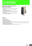
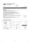
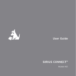
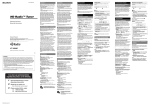
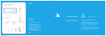
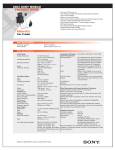
Installation + User Guide
SNYSC1 Sony Compatible
SiriusConnect ™ Interface
Congratulations on the Purchase of your new SNYSC1
Sony Compatible SiriusConnect Interface
The SNYSC1 is a specially designed interface that allows a Sony® SAT-Radio Ready
headunit to correctly communicate and control a SIRIUS® Satellite Radio Tuner.
The SNYSC1 is compatible with all Sony SAT-Radio-Ready headunits. It can be connected to either the SCC1 SiriusConnect Vehicle Tuner or the SCVDOC1 SiriusConnect Vehicle Dock with a compatible Dock and Play or portable SIRIUS radio attached.
Reguires Sony
SAT-Radio-Ready Headunit...
...and a SiriusConnect tuner (SCC1) or a
vehicle kit (SCVDOC1) and compatible
Dock and Play or Portable radio
Table of Contents
Table of Contents. . . . . . . . . . . . . . . . . . . . . . . . . . . 3
Copyrights & Trademarks . . . . . . . . . . . . . . . . . . . . . .
4
Warning and Safety Information. . . . . . . . . . . . . . . . . . .
FCC Information . . . . . . . . . . . . . . . . . . . . . . . . . . . . .
Canadian Compliance . . . . . . . . . . . . . . . . . . . . . . . . . . .
Safety Precautions. . . . . . . . . . . . . . . . . . . . . . . . . . . . .
5
5
6
6
Package Contents. . . . . . . . . . . . . . . . . . . . . . . . . . . 7
Compatibility . . . . . . . . . . . . . . . . . . . . . . . . . . . . . 9
Connectors . . . . . . . . . . . . . . . . . . . . . . . . . . . . .
10
Installation. . . . . . . . . . . . . . . . . . . . . . . . . . . . . 12
Mounting the SNYSC1 Interface . . . . . . . . . . . . . . . . . . . . . . 12
Wiring the SNYSC1 Interface. . . . . . . . . . . . . . . . . . . . . . . 15
Operation . . . . . . . . . . . . . . . . . . . . . . . . . . . . . .
20
Specifications. . . . . . . . . . . . . . . . . . . . . . . . . . . .
21
[ Table of Contents ]
Copyrights & Trademarks
© 2007 Sirius Satellite Radio Inc. All Rights Reserved.
® “SIRIUS”, the SIRIUS dog logo, channel names and logos are trademarks of Sirius
Satellite Radio Inc. “Sony” is a registered trademark of Sony Electronics Inc. “iPod” is
a registered trademark of Apple Inc. All Rights Reserved.
™ “SiriusConnect”, is a trademark of Sirius Satellite Radio Inc. UniLink is a trademark
of Sony Electronics Inc.
Hardware, subscription, and activation fee required. For full Terms & Conditions, visit
http://sirius.com. Prices and programming are subject to change. Not available in HI
and AK. Equipment and subscription sold separately. Installation required with some
equipment.
[ Copyrights & Trademarks ]
Warning and Safety Information
FCC Information
This device complies with part 15 of the FCC Rules. Operation is subject to the following two conditions:
1. This device may not cause harmful interference, and
2. This device must accept any interference received, including interference that
may cause undesired operation.
Note: This equipment has been tested and found to comply with the limits for
a CLASS B digital device, pursuant to Part 15 of the FCC Rules. These limits
are designed to provide reasonable protection against harmful interference
when the equipment is operated in a commercial environment. This equipment
generates, uses, and can radiate radio frequency energy and, if not installed
and used in accordance with the instructions, may cause harmful interference
to radio communications. However, there is no guarantee that interference will
not occur in a particular installation. If this equipment does cause harmful interference to radio or television reception, which can be determined by turning the
equipment off and on, the user is encouraged to try to correct the interference
by one or more of the following measures:
1. Reorient or relocate the receiving antenna.
2. Increase the separation between the equipment and the receiver.
3. Connect the equipment into an outlet on a circuit different from that to
which the receiver is connected.
4. Consult the dealer or an experienced radio/TV technician for help.
WARNING
Changes or modifications not expressly approved by the manufacturer could void the
user’s authority to operate the equipment.
[ Warning and Safety Information ]
Canadian Compliance
This Class B digital apparatus complies with Canadian ICES-003.
Cet appareil numérique de la classe B est conforme à la norme NMB-003 du Canada.
Safety Precautions
Be sure to observe the following warnings. Failure to follow these safety instructions
and warnings may result in a serious accident and/or personal injury.
• Install the cables and wiring so that it is not crimped or pinched by screws or
sharp metal edges. Route the cables away from moving parts or sharp pointed
edges. This will prevent crimping and damage to the wiring. If the wiring must pass
through a metal hole, be sure to use a rubber grommet to prevent the wire’s insulation from being cut by the metal edge of the hole.
• Do not open, disassemble or alter the unit in any way. Doing so may result in fire,
electric shock or product damage.
• Do not insert any objects into the unit. Doing so may result in fire, electric shock or
product damage.
• Do not install the unit to high levels of humidity, moisture or dust. Doing so can
result in electric shock or product failure.
[ Warning and Safety Information ]
Package Contents
The following items are included with your purchase of the SNYSC1. Unpack the materials carefully and make sure that everything shown is present. If anything is missing
or damaged, or if the device fails to operate properly, notify your dealer immediately. It
is recommended that you retain the original carton and packing materials in case you
need to ship your kit in the future.
SNYSC1 SiriusConnect Interface Adapter
Power Harness
[ Package Contents ]
UniLink™ Data Cable
[ Package Contents ]
Audio Cable
Mounting screws (x4)
Compatibility
The SNYSC1 SiriusConnect Interface is compatible with all Sony SAT-Radio-Ready
headunits.
The UniLink input pass-through connector on the SNYSC1 can support the Sony
iPOD adapter or Sony CD Changer.
[ Compatibility ]
Connectors
Figure 1 and the table following identify and describe the connectors of the SNYSC1.
AUDIO IN
L/R
L
UNILINK
IN
SC
INPUT
UNILINK
OUT
POWER
SC INPUT
UNILINK OUT
AUDIO
OUT
R
AUDIO IN
UNILINK IN
POWER
AUDIO
OUT L/R
Figure 1
Description of the SNYSC1 Connectors
Connector
Description
Audio In Connectors L/R
Connects to the audio output of a Sony CD Changer,
iPod adapter, or other UniLink compatible device
UniLink In Connector
Connects to a Sony CD Changer, iPod® adapter, or
other UniLink compatible device
Audio Out Cable
Connects to the UniLink Audio input on the Sony
headunit
10 [ Connectors ]
Description of the SNYSC1 Connectors
Connector
Description
SC Input Connector
Connects to the SCC1 tuner or the SCVDOC1 dock
UniLink Out Connector
Connects to the UniLink connector on the Sony
headunit
Power Connector
Connects to the vehicle’s DC power/ground using the
provided power harness
Yellow: Connects to a positive DC voltage source
Black: Connects to vehicle ground
[ Connectors ]
11
Installation
It is recommended that prior to starting the installation, you thoroughly read these
installation instructions and then follow them carefully for a successful installation.
Mounting the SNYSC1 Interface
Consider the mounting location carefully. You should make sure that you avoid the
following:
•
•
•
•
Any location where the device is exposed to moisture.
Any location where the device is exposed to extreme heat.
Any location where the device cannot get adequate ventilation.
Any location that would interfere with moving parts on the vehicle or hamper driving.
Be sure that you find a mounting location that is flat and has clearance above the
device to prevent any damage as well as allowing for ventilation.
The SNYSC1 can be mounted in three different ways:
1. By using attached mounting plate with the provided screws to secure the device
to the vehicle. (Figure 2) Caution: If you are attaching the device directly to the
vehicle’s chassis, be sure that you check to make sure the area behind the device
is free from moving parts, fuel or brake lines, wire harnesses, or any other items
which may get damaged by drilling a mounting hole or using the supplied screws.
2. By removing the mounting plate from the SNYSC1, and instead mounting it
directly to a surface using either double-sided stick tape, hook and loop, or other
adhesive material (not provided). Simply remove the two screws on the bottom of
the SNYSC1 to remove the bracket, as shown in Figure 3.
12 [ Installation ]
3. By attaching the SNYSC1 and the SIRIUS SCC1 tuner together. To connect the
devices together, simply remove the mounting brackets from each device, rotate
them 90°, and connect them together as shown in Figure 4.
Figure 2
Figure 3
[ Installation ]
13
Figure 4
14 [ Installation ]
Wiring the SNYSC1 Interface
Power Harness
Connect the yellow wire of the power harness to a suitable +12V power source in the
vehicle, which is capable of providing 1 amp of power. Connect the black wire to the
vehicle ground. (Figure 5)
The power harness for the SNYSC1 has power filter box which contains a fuse for the
12V battery connection. Figure 5 also shows the location and type of fuse, and also
the identifies the pin-outs of the power connector.
Power Connector
BATT (Yellow)
Power Filter
with Fuse
GND
(Black)
BATTERY
(As Viewed From the Wire End of the Plug)
No Connection
GND
Battery 12 VDC
No Connection
2A AGC Type Fuse
Figure 5
[ Installation ]
15
System Wiring
There are three possible wiring configurations:
1. A simple configuration which utilizes only the SNYSC1 Interface. (Figure 6 on
page 17.)
2. A configuration which utilizes an iPod adapter in addition to the SNYSC1 Interface. (Figure 7 on page 18.)
3. A configuration which utilizes an iPod adapter and a CD changer in addition
to the SNYSC1 Interface. (Figure 8 on page 19.) This configuration requires a
Sony XA-C40 Source Selector (not provided). Please note that it is important to
connect each device to the correct input ports of the source selector, as shown
in Figure 8.
16 [ Installation ]
SIRIUS
SCC1
OR
SC OUTPUT
SIRIUS
SCVDOC1
ANTENNA
SIRIUS
SNYSC1
UNILINK IN
AUDIO OUT SC INPUT
AUDIO IN
UNILINK OUT POWER
Sony Headunit
Figure 6
[ Installation ]
17
Sony XA-110IP
iPod Adapter
SIRIUS
SCC1
SIRIUS
SCVDOC1
OR
SC OUTPUT
ANTENNA
UNILINK IN
AUDIO IN
SIRIUS
SNYSC1
AUDIO OUT SC INPUT
Figure 7
18 [ Installation ]
UNILINK OUT POWER
Sony Headunit
SIRIUS
SCC1
SC OUTPUT
Connecting the UniLink Cables:
When using a Sony Source Selector
such as the XA-C40 or XA-300, it is
important to connect the devices to the
correct UniLink inputs on the source
selector:
Input 1 = SIRIUS SNYSC1
Input 2 = Sony XA-110IP iPod Adapter
Input 3 = Sony CD Changer
SIRIUS
SCVDOC1
OR
ANTENNA
Sony XA-110IP
iPod Adapter
SIRIUS
SNYSC1
UNILINK IN
AUDIO OUT SC INPUT
2
AUDIO IN
UNILINK OUT POWER
1
Sony XA-C40
Source
Selector
Sony Headunit
3
Sony CD Changer
Figure 8
[ Installation ]
19
Operation
For operation instructions, please consult the instruction manual which accompanied
your headunit.
Additional instructions may also be found in the manual which accompanied your
SIRIUS SCC1 tuner or SCVDOC1 dock and SIRIUS radio.
20 [ Operation ]
Specifications
Power Requirements . . . . . . . . . . . . . . . . . . . . . . . . . . . . . . . . . . . . . . . . . 11-14 VDC, 1A
In-Line fuse (Located inside Filter Box) . . . . . . . . . . . . . . . . . . . . . . . . . . . . . . . 1A AGC
Operation Temperature . . . . . . . . . . . . . . . . . . . . . . . . . -20° to +85° C (-4° to +185° F)
Dock Dimensions (Width x Height x Depth) . . . . . . . . . . . . . . . 86mm x 87mm x 33.2mm
Weight . . . . . . . . . . . . . . . . . . . . . . . . . . . . . . . . . . . . . . . . . . . . . . . . . . . . . . . . . . . . 120g
UniLink Cable Length . . . . . . . . . . . . . . . . . . . . . . . . . . . . . . . . . . . . . . . . . . . . . . . . 2.5m
RCA Audio Cable Length . . . . . . . . . . . . . . . . . . . . . . . . . . . . . . . . . . . . . . . . . . . . . 2.5m
[ Specifications ]
21
sirius.com
SIRIUS Satellite Radio Inc.
1221 Avenue of the Americas
New York, NY 10020
800.869.5590
SNYSC1 SiriusConnect™ Interface (SNYSC1120407a)
OO.ABCD1.001