1
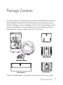
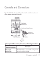
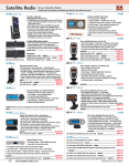
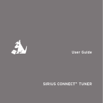
User Guide Sirius Connect ™ Home Kit Congratulations on the Purchase of your new SCHDOC1 SiriusConnect Home Docking Kit The SCHDOC1 SiriusConnect™ Home Docking Kit will turn your SIRIUS Dock & Play or portable radio into a dedicated tuner, allowing you to control your SIRIUS radio from your Sirius Ready home audio system. The SCHDOC1 is designed to work with any Sirius Ready or SAT Radio Ready A/V receiver or audio system. Some systems that only have RS232 control (and no 8-pin DIN connector) require the SCHDOC1P kit instead. Please consult the manufacturer for more details concerning compatibility. The SCHDOC1 is compatible with the SIRIUS® Stiletto™, Sportster™, Starmate™, Stratus™ radios that have the Sirius Universal Docking Connector. For the latest information about this and other SIRIUS products and accessories, visit http://www. sirius.com. Compatible with Sirius-Ready or SATRadio Ready audio systems: Table of Contents Table of Contents. . . . . . . . . . . . . . . . . . . . . . . . . . . 3 Copyrights & Trademarks . . . . . . . . . . . . . . . . . . . . . . 4 Warning and Safety Information. . . . . . . . . . . . . . . . . . . FCC Information . . . . . . . . . . . . . . . . . . . . . . . . . . . . . Canadian Compliance . . . . . . . . . . . . . . . . . . . . . . . . . . . Safety Precautions. . . . . . . . . . . . . . . . . . . . . . . . . . . . . 5 5 6 6 Package Contents. . . . . . . . . . . . . . . . . . . . . . . . . . . 7 Controls and Connectors . . . . . . . . . . . . . . . . . . . . . . 9 Installation. . . . . . . . . . . . . . . . . . . . . . . . . . . . . Attaching the Radio Adapter. . . . . . . . . . . . . . . . . . . . . . . . Connecting the Dock to the SIRIUS-Ready Receiver . . . . . . . . . . . . . . Installing the Indoor/Outdoor Antenna. . . . . . . . . . . . . . . . . . . . Connecting the AC Power Adapter . . . . . . . . . . . . . . . . . . . . . 11 11 13 14 21 Operation . . . . . . . . . . . . . . . . . . . . . . . . . . . . . . 22 Specifications. . . . . . . . . . . . . . . . . . . . . . . . . . . . 24 [ Table of Contents ] Copyrights & Trademarks © 2007 Sirius Satellite Radio Inc. All Rights Reserved. ® “SIRIUS”, the SIRIUS dog logo, channel names and logos are trademarks of Sirius Satellite Radio Inc. All Rights Reserved. ™ “SiriusConnect”, “Stiletto”, “Sportster”, “Starmate”, and “Stratus” are trademarks of Sirius Satellite Radio Inc. Hardware, subscription, and activation fee required. For full Terms & Conditions, visit http://sirius.com. Prices and programming are subject to change. Not available in HI and AK. Equipment and subscription sold separately. Installation required with some equipment. [ Copyrights & Trademarks ] Warning and Safety Information FCC Information This device complies with part 15 of the FCC Rules. Operation is subject to the following two conditions: 1. This device may not cause harmful interference, and 2. This device must accept any interference received, including interference that may cause undesired operation. Note: This equipment has been tested and found to comply with the limits for a CLASS B digital device, pursuant to Part 15 of the FCC Rules. These limits are designed to provide reasonable protection against harmful interference when the equipment is operated in a commercial environment. This equipment generates, uses, and can radiate radio frequency energy and, if not installed and used in accordance with the instructions, may cause harmful interference to radio communications. However, there is no guarantee that interference will not occur in a particular installation. If this equipment does cause harmful interference to radio or television reception, which can be determined by turning the equipment off and on, the user is encouraged to try to correct the interference by one or more of the following measures: 1. Reorient or relocate the receiving antenna. 2. Increase the separation between the equipment and the receiver. 3. Connect the equipment into an outlet on a circuit different from that to which the receiver is connected. 4. Consult the dealer or an experienced radio/TV technician for help. WARNING Changes or modifications not expressly approved by the manufacturer could void the user’s authority to operate the equipment. [ Warning and Safety Information ] Canadian Compliance This Class B digital apparatus complies with Canadian ICES-003. Cet appareil numérique de la classe B est conforme à la norme NMB-003 du Canada. Safety Precautions Be sure to observe the following warnings. Failure to follow these safety instructions and warnings may result in a serious accident and/or personal injury. • Install the cables and wiring so that it is not crimped or pinched by screws or sharp metal edges. Route the cables away from moving parts or sharp pointed edges. This will prevent crimping and damage to the wiring. If the wiring must pass through a metal hole, be sure to use a rubber grommet to prevent the wire’s insulation from being cut by the metal edge of the hole. • Do not open, disassemble or alter the unit in any way. Doing so may result in fire, electric shock or product damage. • Do not insert any objects into the unit. Doing so may result in fire, electric shock or product damage. • Do not install the unit to high levels of humidity, moisture or dust. Doing so can result in electric shock or product failure. [ Warning and Safety Information ] Package Contents The following items are included with your purchase of the SCHDOC1 SiriusConnect Home Docking Kit. Unpack the kit carefully and make sure that everything shown is present. If anything is missing or damaged, or if the kit fails to operate properly, notify your dealer immediately. It is recommended that you retain the original carton and packing materials in case you need to ship your kit in the future. Radio Adapter 1* Radio Adapter 3 SiriusConnect Dock Radio Adapter 2 Radio Adapter 4 * Note that the Radio Adapter 1 shown above is pre-installed on the SiriusConnect Dock. [ Package Contents ] SiriusConnect Interface Cable AC Adapter Indoor/Outdoor Antenna The following compatibility chart shows which SIRIUS radios are compatible with each radio adapter: Radio Adapter Adapter 1 (preinstalled) Compatible with these SIRIUS radios Sportster 5, Starmate 3 & 4, Stratus & Stratus 4 Adapter 2 Sportster 3 & 4 Adapter 3 Stiletto 10 & 100 (The Stiletto 10 & 100 require v1.1 software (or higher) to support SiriusConnect mode.) Adapter 4 Stilletto 2 [ Package Contents ] Controls and Connectors Figure 1 and the table following identify and describe the controls, connectors, and various mounting connections of the dock. Radio Adapter Mounting Hole Radio Adapter Alignment Holes Sirius Universal Docking Connector SiriusConnect Interface Connector Antenna Connector Radio Release Button Power Connector Figure 1 Description of Dock Controls, Connectors, and Mounting Connections Control/Connector/ Mounting Connection Radio Adapter Mounting Hole Description The Radio Adapter is secured to the dock by attaching it with a screw to this hole. [ Connectors & Controls ] Description of Dock Controls, Connectors, and Mounting Connections Control/Connector/ Mounting Connection Description Radio Release Button Pressing this button releases the SIRIUS radio from the dock. Radio Adapter Alignment Holes Tabs on the radio adapter align with these holes for correct placement in the dock. Sirius Universal Docking Connector This connector plugs into the bottom of the SIRIUS radio. Antenna Connector The SIRIUS indoor/outdoor antenna is connected to this connector. SiriusConnect Interface Connector The SiriusConnect interface cable connects to this connector. The other end of the DIN cable connects to the audio system. Power Connector The AC power adapter is connected to this connector. 10 [ Connectors & Controls ] Installation It is recommended that prior to starting the installation, you read this installation section completely and then follow the instructions. In addition, consult the manual of the receiver to which you will be connecting the dock to determine any required installation configuration. When installing the dock in your home, choose a location in close proximity to your SIRIUS-Ready receiver, and also where the cable from the indoor/outdoor antenna can reach the dock. The location should be easily accessible and should not be located where it will be in direct sunlight which will affect the visibility of the display screen. Attaching the Radio Adapter You should attach the correct radio adapter for your SIRIUS radio to the dock. There are four different radio adapters provided for the SIRIUS radios. One of the radio adapters is pre-installed on the dock but may need to be removed and replaced with a different adapter for your particular SIRIUS radio. The different radio adapters are identified on page 7 and you should consult the compatibility chart on page 8 to identify the adapter for your SIRIUS radio. If you need to change the radio adapter, refer to Figure 2 and remove mounting screw A. Then remove the pre-installed radio adapter. Align the correct radio adapter for your radio with the dock, verifying that the tabs on the rear of the adapter align with the corresponding alignment holes on the dock. (Refer to Figure 1 on page 9 for the location of the alignment holes). When the radio adapter is correctly aligned on the dock, re-install screw A. [ Installation ] 11 Radio Adapter Mounting Screw (A) Radio Adapter Figure 2 When the radio adapter has been attached to the dock, you can place your SIRIUS radio into the dock. 12 [ Installation ] Connecting the Dock to the SIRIUS-Ready Receiver The SCHDOC1 SiriusConnect Home Docking Kit is designed to work with any SiriusReady or SAT Radio Ready receiver. Please consult the user manual or manufacturer for your receiver for more details concerning compatibility. Some systems that only have RS232 control (and no 8-pin DIN connector) require the SCHDOC1P kit instead. Figure 3 shows a Sirius-Ready or SAT Radio Ready receiver using the provided 8-PIN DIN cable. Note that the receiver must be capable of directly communicating with the SCHDOC1 SiriusConnect Dock protocol. Indoor/Outdoor Antenna Dock SiriusConnect 8-pin DIN Cable SIRIUS-Ready Receiver AC Adapter Figure 3 [ Installation ] 13 Installing the Indoor/Outdoor Antenna Before installing the indoor/outdoor antenna, read this entire section. To ensure consistent reception of the SIRIUS signal in your home, it is important that the antenna be oriented correctly. Note the following Best, Better, and Good considerations for antenna placement. BEST reception can be achieved by mounting the antenna on the outside of the building on a soffit at the roof, with a clear 360 degree view of the sky. (Figure 4, A) This position will afford the best view of the sky for best reception. When placed in this location, an antenna extension cable may be required. BETTER reception can be achieved by placing the antenna outside on a window, on a porch, or on a patio (Figure 4, B), or by mounting it to the side of the building. In all cases, try to achieve the best possible clear view of the sky. 14 [ Installation ] A. B. Figure 4 GOOD reception can be achieved by placing the antenna indoors on a windowsill. The window will need to be facing in the direction of the SIRIUS satellites, as described later, and have a clear view of the sky. The antenna may need to be placed on a book to raise it above the level of the window frame. (Figure 5) Note: If your location is in major metropolitan area, the antenna can possibly be located inside the home because terrestrial transmitters are used to boost signal strength. If you are able to achieve a good terrestrial signal with the antenna indoors, you can disregard the remainder of these antenna installation instructions. Refer to the section, Testing and Optimizing the Antenna Signal Strength on page 19 for details about displaying the terrestrial signal strength. [ Installation ] 15 Figure 5 If you cannot obtain a clear 360 degree view of the sky (Best), then for the Better and Good installations you must at least have a clear view of the sky in the direction of the SIRIUS satellites, as shown in the following map diagram. (Figure 6) 16 [ Installation ] SKY NORTH WEST 1 4 5 EAST 3 2 HORIZON SOUTH Figure 6 Use the map to find the area you are located in (1 to 5). Then find the direction in which you need to have a clear view of the sky: Area 1: You will need a location with a clear view of the sky facing EAST or NORTHEAST or SOUTHEAST Area 2: You will need a location with a clear view of the sky facing NORTH or NORTHEAST Area 3: You will need a location with a clear view of the sky facing NORTH or NORTHWEST Area 4: You will need a location with a clear view of the sky facing WEST or NORTHWEST or SOUTHWEST Area 5: You will need a clear view of the sky facing STRAIGHT UP (Outdoors only, refer to Figure 4) [ Installation ] 17 The location for the antenna must have an unobstructed view of the sky in the direction indicated for your area. (Figure 7) For example, suppose you live in Area 2. You determined that your antenna will need to have a clear view of the sky facing North or Northeast. The exact direction is determined by your specific location in Area 2 relative to the X on the map: If you live in Texas, you will need a more North facing clear view of the sky whereas if you live in southern California, you will need a more Northeast facing clear view of the sky. NORTH EAST WEST SOUTH Figure 7 Once you have found a suitable location for the antenna, route the antenna cable to the home dock. Be sure you avoid any obstructions that could crimp, kink, or twist the cable. Use protective grommets wherever rough openings are encountered. If the antenna is installed outdoors, route the cable from the antenna location to the interior of the home, working the cable through the basement, under a window sill, etc., and make adjustments to take up cable slack as necessary. Connect the antenna cable to the antenna connector of the dock. (Refer to Figure 1 on page 9.) Optional antenna extension cables are available if needed. 18 [ Installation ] Testing and Optimizing the Antenna Signal Strength The stronger the SIRIUS signal strength, the less likely it is that you will experience an interruption of the audio when listening to a broadcast. To assist you in adjusting the antenna aiming for optimal reception, your SIRIUS radio or SIRIUS-Ready receiver can display a screen showing the strength of the SIRIUS signal being received, similar to Figure 8. To access the antenna aiming or signal indicator screen, consult the user guide which accompanied your SIRIUS radio or SIRIUS-Ready receiver. The SATELLITE portion of the display screen (Figure 8) shows the strength of the signal being received from the satellite, while the TERRESTRIAL portion of the display screen shows the strength of the signal being received from terrestrial based transmitters, if available. Antenna Aiming Adjust your antenna position to maximize signal strength. SATELLITE TERRESTRIAL Press BACK when done Figure 8 Aiming the antenna consists of two adjustments. The first adjustment is to tilt the clamshell at a 45 degree angle. While observing the signal strength, make small adjustments to the angle of tilt of the clamshell until the highest possible signal strength is achieved. (Figure 9) [ Installation ] 19 THIS SURFACE OF THE ANTENNA SHOULD BE POINTED AT THE SKY TOWARDS THE DIRECTION OF THE SATELLITES Figure 9 The second adjustment is to turn the antenna slightly to the left or right until the highest possible signal strength is achieved. (Figure 10) Figure 10 20 [ Installation ] If you find that it is not possible to receive a good SIRIUS signal in your location, SIRIUS offers a outdoor home antenna which can be mounted to the exterior of the home. The outdoor home antenna offers more mounting options, such as mounting on an existing mast or satellite dish mast, and provides 30 ft. of antenna cable. For more tips on installing the antenna, please visit the SIRIUS website at http://www. sirius.com and click on the Install/Activate link. Connecting the AC Power Adapter Connect the AC Power Adapter cable to the power connector of the dock. (Refer to Figure 1 on page 9.) Plug the AC Power Adapter into a wall outlet. [ Installation ] 21 Operation Before you can listen to the SIRIUS service, you need to subscribe to the Sirius Satellite Radio service if you have not done so already. Please be sure to follow the activation instructions for your specific SIRIUS radio as well as your receiver. Place your SIRIUS radio into the dock (Figure 11), aligning the tabs at the edges of the radio adapter with the groves in your SIRIUS radio. Gently push the radio down until it is fully seated in the dock. (Your radio may differ from the radio shown). To remove the radio from the dock, press the release button (Figure 11) while pulling the radio out of the dock. + back home display options Figure 11 22 [ Operation ] For operating instructions consult the owners manual of your audio system. When your SIRIUS radio is connected via the SCHDOC1 SiriusConnect Home Docking Kit to your receiver, the buttons and controls of the SIRIUS radio will be disabled, and a SiriusConnect message or logo will be displayed. [ Operation ] 23 Specifications Power Requirements . . . . . . . . . . . . . . . . . . . . . . . . . . . . . . . . . . . . . . . . . . . . 5.2V DC, 2A Operation Temperature . . . . . . . . . . . . . . . . . . . . . . . . . . . -5° to +40° C (23° to 104° F) Signal-to-noise (S/N) (with radio connected) . . . . . . . . . . . . . . . . . . . . . . . . . . . . . >73dB Output Level (with radio connected) . . . . . . . . . . . . . . . . . . . . . . . . . . . . . . . . 2.0v RMS Antenna Type . . . . . . . . . . . . . . . . . . . . . . . . . . . . . Indoor/Outdoor Windowsill Antenna Antenna Cable Length . . . . . . . . . . . . . . . . . . . . . . . . . . . . . . . 21’ (single micro-cable) Antenna Connector Type . . . . . . . . . . . . . . . . . . . . . . . . . . . . . . . . . . . . . . . . . . . . . SMB Data Interface . . . . . . . . . . . . . . . . 8-PIN DIN Control Port (audio, power, serial control) Dock Dimensions (Height x Width x Depth) . . . . . . . . . . . . . . . . 48mm x 55mm x 49mm Radio Adapter 1 Dimensions . . . . . . . . . . . . . . . . . . . . . . . . 32.5mm x 55mm x 13.5mm Radio Adapter 2 Dimensions . . . . . . . . . . . . . . . . . . . . . . . . . 33mm x 118mm x 12.5mm Radio Adapter 3 Dimensions . . . . . . . . . . . . . . . . . . . . . . . . 33.5mm x 55mm x 18.5mm Radio Adapter 4 Dimensions . . . . . . . . . . . . . . . . . . . . . . . . 33.5mm x 55mm x 18.5mm 24 [ Specifications ] sirius.com SIRIUS Satellite Radio Inc. 1221 Avenue of the Americas New York, NY 10020 800.869.5590 SCHDOC1 (SCHDOC1122007a) OO.ABCD1.001