1
SX-550 WLAN Module
Developer’s Reference Guide
Part Number 40183-101
Revision D
© 2006 silex technology america, Inc.. All rights reserved.
January, 2006
silex technology america SPECIFICALLY DISCLAIMS THE IMPLIED WARRANTIES OF MERCHANTABILITY AND FITNESS
OF THIS PRODUCT FOR A PARTICULAR PURPOSE. silex shall not be liable for any errors contained in this manual or for
any damages resulting from loss of use, data, profits, or any incidental or consequential damages arising from the use of
SILEX products or services. The information contained in this documentation is subject to change without notice.
Information and descriptions contained herein are the property of silex. Such information and descriptions may
not be copied, disseminated, or distributed without the express written consent of silex. This publication is subject
to change without notice.
The software embedded in this SX-550 module includes eCos, the Embedded Configurable Operating System.
eCos is licensed under a GNU GPL compatible Free Software License. In compliance with the eCos license, the
silex is offering the eCos source code for this product on our web site at http://www.silexamerica.com. A copy of
the eCos and GNU General Public License are available in the license folder on the CDROM that ships with this
product.
Trademarks
ExtendView is a trademark of silex technology america, Inc. All other company or product names referenced in
this document may be trademarks or registered trademarks of their respective owners.
silex technology america, Inc.
www.silexamerica.com
Part Number 40183-101
Contents
About This Reference Guide ..................................................................................................................................... 1
Safety Precautions................................................................................................................................................. 1
Emissions Disclaimer............................................................................................................................................. 1
Chapter 1: Introduction .............................................................................................................................................. 3
Chapter 2: Getting Started......................................................................................................................................... 5
Verify Development Kit Contents ........................................................................................................................... 6
Installing the SX-550 WLAN Module...................................................................................................................... 7
Chapter 3: SX-550 Evaluation Daughtercard Hardware Configuration.................................................................... 9
Monitoring Module Status ...................................................................................................................................... 9
OEM Interface ...................................................................................................................................................... 10
Electrical Characteristics...................................................................................................................................... 12
Power Input ...................................................................................................................................................... 12
Power Management ......................................................................................................................................... 12
Serial Peripheral Interface................................................................................................................................ 12
Serial Ports ....................................................................................................................................................... 13
General Purpose IO ......................................................................................................................................... 15
LEDs and General Purpose IO Signals............................................................................................................ 16
RS-232 Cable ................................................................................................................................................... 17
Additional OEM Interface Signals .................................................................................................................... 17
OEM Interface Electrical Characteristics.......................................................................................................... 18
Chapter 4: Using the SX-550 WLAN Module .......................................................................................................... 19
Evaluation Module Connections .......................................................................................................................... 19
Using the Wireless Method .............................................................................................................................. 19
Using the Wired Ethernet Method .................................................................................................................... 20
Access silex Console Interface ............................................................................................................................ 20
Generating Configuration Data......................................................................................................................... 21
Chapter 5: Accessing Configuration Parameters .................................................................................................... 23
Access ExtendView Utility.................................................................................................................................... 23
Installing ExtendView Utility ............................................................................................................................. 24
Using ExtendView Utility .................................................................................................................................. 25
Access HTTP Pages............................................................................................................................................ 27
Access Internal Command Console..................................................................................................................... 28
Using Telnet Session ....................................................................................................................................... 29
Using Terminal Emulator through the Serial Port............................................................................................. 29
Using AT Modem Commands.............................................................................................................................. 30
Standard AT Commands Supported ................................................................................................................ 30
Response Codes ................................................................................................................................................. 32
silex
Part Number 40183-101
Page i
Chapter 6: Setting Configuration Parameters ........................................................................................................ 33
Factory Default Settings....................................................................................................................................... 33
Restoring Factory Default Settings .................................................................................................................. 34
Modify Basic Settings........................................................................................................................................... 34
Changing Serial Settings.................................................................................................................................. 34
Modifying TCP/IP Settings ............................................................................................................................... 36
Configure Simple Network Management Protocol............................................................................................... 39
Configuring GPIO Alerts and Traps ..................................................................................................................... 40
Configuring Serial Port Monitor Alert and Trap Configuration ............................................................................. 44
Chapter 7: Designing with the SX-550 .................................................................................................................... 46
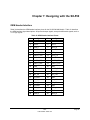
OEM Header Interface ......................................................................................................................................... 46
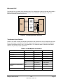
Antenna Connectors ............................................................................................................................................ 48
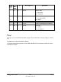
Ethernet PHY ....................................................................................................................................................... 49
Transformer Specification ................................................................................................................................ 49
General Purpose I/O Interface ............................................................................................................................. 50
Power ................................................................................................................................................................... 51
Chapter 8: Product Specifications .......................................................................................................................... 52
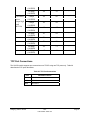
TCP Port Connections ......................................................................................................................................... 55
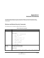
Appendix A: Console Commands........................................................................................................................... 56
Wireless and Network Security Commands ........................................................................................................ 56
Port Commands ................................................................................................................................................... 62
Server Information Commands ............................................................................................................................ 63
Service Commands.............................................................................................................................................. 65
String Commands ................................................................................................................................................ 67
TCP/IP Commands .............................................................................................................................................. 68
Power Configuration Commands ......................................................................................................................... 71
Firmware Update.................................................................................................................................................. 71
Miscellaneous Commands................................................................................................................................... 73
Help Commands .................................................................................................................................................. 73
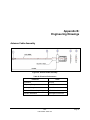
Appendix B: Engineering Drawings ........................................................................................................................ 74
Antenna Cable Assembly..................................................................................................................................... 74
Page ii
silex
Part Number 40183-101
Contents
Figures
Figure 1 Processor and Wireless LAN Radio PCB .................................................................................................. 3
Figure 2 Installing WLAN Module in Daughtercard .................................................................................................. 5
Figure 3 WLAN Module Inserted in Daughtercard ................................................................................................... 7
Figure 4 Antenna Connectors................................................................................................................................... 7
Figure 5 SX-550 Evaluation Daughtercard............................................................................................................... 8
Figure 6 JP1 Header............................................................................................................................................... 12
Figure 7 Optional Serial Signals .............................................................................................................................. 13
Figure 8 Serial Port DB-9 Connector...................................................................................................................... 14
Figure 9 RS-232 Cable Pinouts.............................................................................................................................. 17
Figure 10 ExtendView Main Page .......................................................................................................................... 25
Figure 11 ExtendView New View Window ............................................................................................................. 25
Figure 12 Create View with Default Settings.......................................................................................................... 26
Figure 13 ExtendView Window............................................................................................................................... 26
Figure 14 ExtendView Configuration Window ........................................................................................................ 27
Figure 15 SX-550 Home Page .............................................................................................................................. 28
Figure 16 Output Port Tab...................................................................................................................................... 34
Figure 17 Serial Settings Window .......................................................................................................................... 35
Figure 18 TCP/IP Window ...................................................................................................................................... 36
Figure 19 Change Password Window .................................................................................................................... 37
Figure 20 Advanced TCP/IP Configuration Window .............................................................................................. 38
Figure 21 SNMP Traps........................................................................................................................................... 40
Figure 22 Main and Auxiliary Antenna Connectors ................................................................................................ 48
Figure 23 Circuit Diagram with Transformer .......................................................................................................... 49
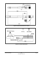
Figure 24 Antenna Cable Assembly ....................................................................................................................... 74
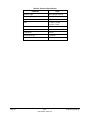
Figure 25 Electrical Specifications for Antenna...................................................................................................... 75
Figure 26 Connector Specifications........................................................................................................................ 75
Tables
Table 1 Development Kit Contents........................................................................................................................... 6
Table 2 Status Monitors............................................................................................................................................. 9
Table 3 OEM Interface Pinout ................................................................................................................................ 10
Table 4 OEM Interface Signal Description .............................................................................................................. 11
Table 5 Logical Serial Port Signal Descriptions ..................................................................................................... 13
Table 6 DB-9 Pinouts for RS-232 Mode ................................................................................................................. 14
Table 7 General Purpose IO Signal Descriptions................................................................................................... 15
Table 8 General Purpose I/O Signal Description ................................................................................................... 15
Table 9 LED and GPIO Descriptions...................................................................................................................... 16
Table 10 RS-232 Cable Pinout Description............................................................................................................ 17
Table 11 OEM Signal Parameter Descriptions....................................................................................................... 18
Table 12 Port Settings ............................................................................................................................................ 20
Table 13 Pushbutton Functions.............................................................................................................................. 21
Table 14 ExtendView System Requirements ......................................................................................................... 24
Table 15 Port Settings ............................................................................................................................................ 30
Table 16 AT Commands......................................................................................................................................... 31
Table 17 Extended AT Commands ........................................................................................................................ 32
Table 18 Response Codes ..................................................................................................................................... 32
Table 19 Factory Default Settings .......................................................................................................................... 33
Table 20 Serial Setting Parameters........................................................................................................................ 35
Table 21 TCP/IP Settings ....................................................................................................................................... 37
Table 22 TCP/IP Configuration Settings................................................................................................................. 38
Table 23 SNMP Commands................................................................................................................................... 39
Table 24 SNMP Trap Settings................................................................................................................................ 40
Contents
silex
Part Number 40183-101
Page iii
Table 25 GPIO Commands .................................................................................................................................... 41
Table 26 GPIO Trigger Commands........................................................................................................................ 42
Table 27 GPIO Transmit Commands ..................................................................................................................... 43
Table 28 Port Monitor Alert Commands ................................................................................................................ 44
Table 29 TRIGMON Commands ............................................................................................................................ 45
Table 30 OEM Header Interface Pinout ................................................................................................................. 46
Table 31 OEM Interface Signal Description ............................................................................................................ 47
Table 32 Antenna Connector Types....................................................................................................................... 48
Table 33 10/100M Magnetic Specifications............................................................................................................. 49
Table 34 10/100M Magnetics Manufacturers ......................................................................................................... 50
Table 35 GPIO Interface......................................................................................................................................... 50
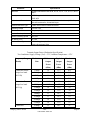
Table 36 Product Specifications ............................................................................................................................. 52
Table 37 Radio Performance Specifications .......................................................................................................... 52
Table 38 TCP Port Connections............................................................................................................................. 55
Table 39 Network Commands ................................................................................................................................ 56
Table 40 Port Commands....................................................................................................................................... 62
Table 41 Server Information Commands ............................................................................................................... 63
Table 42 Service Commands ................................................................................................................................. 65
Table 43 String Commands.................................................................................................................................... 67
Table 44 TCP/IP Commands.................................................................................................................................. 68
Table 45 Power Configuration ................................................................................................................................ 71
Table 46 Firmware Update ..................................................................................................................................... 71
Table 47 Miscellaneous Commands ...................................................................................................................... 73
Table 48 Electrical Performance ............................................................................................................................ 74
Table 49 Electrical Specifications........................................................................................................................... 76
Page iv
silex
Part Number 40183-101
Contents
About This Reference Guide
This reference guide provides detailed specifications, diagrams and additional information required to integrate
the Ethernet and Wireless Serial Server Module in a product. The intended audiences are the developers and
engineers responsible for the integration of the module in another product.
Safety Precautions
To prevent damage to the SX-550 module’s electronic circuit components, follow established ESD practices
and procedures for handling static-sensitive devices. All ESD-sensitive components must be stored and
shipped in ESD-conductive bags or bubble-wrap and labeled as such using the standardized ESD adhesive
warning label.
Ethernet electrical wiring must be at least 6 feet from bare power wiring or lightning rods and associated
wires, and at least 6 inches from other types of wire (antenna wires, doorbell wires, wires from transformers
to neon signs), steam or hot water pipes, and heating devices.
Protectors and grounding wire placed by the service provider must not be connected to, removed, or
modified by the customer.
Emissions Disclaimer
Final emission certification per FCC, CE and other agency requirements are the responsibility of the OEM using
any printed circuit assemblies or other items used in this developer’s kit in their saleable packaged product.
silex
Part Number 40183-101
Page 1
Page 2
silex
Part Number 40183-101
About This Reference Guide
Chapter 1: Introduction
The SX-550 WLAN Module provides a complete solution for integrating networking technology into a
product. It includes an embedded processor, auto-sensing 10baseT/100baseTX Ethernet MAC/PHY,
wireless chipset and embedded operating system with a full networking stack and drivers. The wireless
high speed network interface conforms to the IEEE 802.11a, b, g, and h protocols. The radio is based on
Conexant’s PRISM WorldRadio chipset.
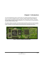
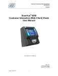
The module consists of two printed circuit boards measuring 44.60 mm by 59.70 mm. One card contains
the processor and memory and the second card contains the 802.11abg wireless LAN radio, as shown in
Figure 1. In addition, the module supports dual diversity antennas and intelligent power control.
Figure 1 Processor and Wireless LAN Radio PCB
silex
Part Number 40183-101
Page 3
Page 4
silex
Part Number 40183-101
Introduction
Chapter 2:
Getting Started
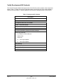
You can install the SX-550 WLAN Module in the SX-550 Evaluation Daughtercard and connect the
cabling, as shown in Figure 2.
Figure 2 Installing WLAN Module in Daughtercard
silex
Part Number 40183-101
Page 5
Verify Development Kit Contents
The SX-550 Evaluation Module Development Kit CAS-1000-I2C product consists of the components
listed in Table 1. Please ensure that all materials listed are present and free from visible damage or
defects before proceeding. If anything appears to be missing or damaged, please contact SILEX.
Table 1 Development Kit Contents
Description
SX-550 Evaluation Daughtercard
2x Antennas with 4-inch Cables
2 x Magnetic Stand with 3-foot Cables
5 VDC 1 Amp Power Supply
AC Power Cord for US
AC Power Cord for Europe
2 x Serial Null Modem Cables with Gender Changer
Plastic bag containing:
4 x Rubber Feet with Adhesive
3 M2 screws
3 M2 nuts
3 3mm nylon spacers
3 8mm nylon spacers
CD containing:
ExtendView Software
Serial Port Emulator
This User’s Guide
Page 6
silex
Part Number 40183-101
Getting Started
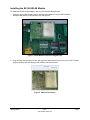
Installing the SX-550 WLAN Module
To install the SX-550 WLAN module in the SX-550 Evaluation Daughtercard:
1. Using the 40-pin OEM header, plug the SX-550 WLAN Module in the SX-550 Evaluation
Daughtercard and secure with screws, nuts and spacers.
Figure 3 WLAN Module Inserted in Daughtercard
2. Plug the main antenna cable into the right top corner Main Antenna Connector on the card. If needed,
plug the auxiliary antenna cable into the Auxiliary Antenna Connector.
Figure 4 Antenna Connectors
Getting Started
silex
Part Number 40183-101
Page 7
3. Connect the magnetic antenna base cable to the antenna cable.
4. Connect the antenna to the base.
5. Connect one serial null-modem cable from the Serial Port 2 DB-9 connector on the evaluation
daughtercard to a serial port on a personal computer or laptop. The PC or laptop acts as a console
port for command line configuration and monitoring.
6. If an Ethernet LAN connection is required, plug a category 5 Ethernet cable into the RJ-45 jack.
The Ethernet interface has Auto-MDIX that automatically detects and configures itself for either a
straight-thru or crossover Ethernet cable.
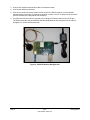
Figure 5 SX-550 Evaluation Daughtercard
Page 8
silex
Part Number 40183-101
Getting Started
Chapter 3:
SX-550 Evaluation Daughtercard
Hardware Configuration
Monitoring Module Status
You can monitor the module status using the yellow, green and orange LED status indicators on the
monitor. Table 2 defines the default functions of the LED status indicators.
Table 2 Status Monitors
Function
Power
Orange
State
Status
On
The module is receiving power
Off
The module is not receiving power
Blinking
The module power supply is malfunctioning
Network Status
Yellow Off
Yellow or Green
Green Off
Yellow On
Green Off
Yellow Blinking
Green Off
Yellow Off
Green On
Yellow Off
Green Blinking
Yellow On
Green On
No network activity
10baseT network active
10baseT network data received
100baseTX network active
100baseTX network data received
Wireless network active, if wireless model
silex
Part Number 40183-101
Page 9
Function
State
Status
Yellow Blinking
Wireless network data received, if wireless model
Green Blinking
OEM Interface
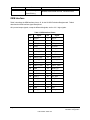
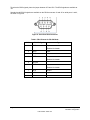
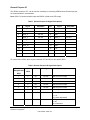
Table 3 describes the OEM interface pinout, J5, for the SX-550 Evaluation Daughtercard. Table 4
describes the OEM interface signal descriptions.
All input and output signals, except the differential signals, are 0 to 3.3 V logic signals.
Table 3 OEM Interface Pinout
Pin
Page 10
Signal
Pin
Signal
1
TPRX+
2
TPTX+
3
TPRX-
4
TPTX-
5
GPIO_7
6
GPIO_8
7
AVDD
8
+3.3VDD
9
UART0_RXD
10
GPIO_9
11
UART0_TXD
12
GPIO_10
13
GND
14
+3.3VDC
15
UART0_RTS
16
UART0_CTS
17
UART1_RTS
18
UART1_CTS
19
GND
20
GND
21
UART1_TXD
22
UART1_RXD
23
GND
24
RESET_N
25
SPI_CS
26
SPI_CLK
27
+3.3VDC
28
GND
29
GPIO_1
30
SPI_SDO
31
GPIO_2
32
SPI_SDI
33
+3.3VDC
34
GND
35
GPIO_3
36
GPIO_4
37
GND
38
GND
39
GPIO_5
40
GPIO_6
silex
Part Number 40183-101
SX-550 Evaluation Daughtercard
Hardware Configuration
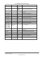
Table 4 OEM Interface Signal Description
Signal
Pin
Type
Description
TPRX+, TPRX-
1,3
Differential
output
Ethernet Transmit Data primary
TPTX+, TPTX-
2,4
Differential
input
Ethernet Receive Data primary
AVDD
7
Power
Ethernet Power Output to transformer
center tap
UART0_RXD
9
Input
Serial Port 1 Receive Data
UART0_TXD
10
Output
Serial Port 1 Transmit Data
UART0_RTS
15
Output
Serial Port 1 Request To Send
UART0_CTS
16
Input
Serial Port 1 Clear to Send
UART1_RXD
22
Input
Serial Port 2 Receive Data
UART1_TXD
21
Output
Serial Port 2 Transmit Data
UART1_RTS
17
Output
Serial Port 2 Request To Send
UART1_CTS
18
Input
Serial Port 2 Clear to Send
GPIO1, GPIO2,
GPIO3, GPIO4,
GPIO5, GPIO6,
GPIO7, GPIO8,
GPIO9, GPIO10
29, 31, 35, 36,
39, 40, 5, 6,
10, 12
Input/Output
General Purpose Input/Output Signals 110, User defined
SPI_CS
25
Output
Serial Peripheral Interface Chip Select
(high-true)
SPI_SDO
30
Output
Serial Peripheral Interface Data Out
SPI_SDI
32
Input
Serial Peripheral Interface Data In
SPI_CLK
26
Output
Serial Peripheral Interface Clock
RESET_N
24
Output
Power-on Reset (low true)
+3.3VDC
8, 14, 27, 33
Power
Power VCC Input
GND
13, 19, 20, 23,
28, 34, 37, 38
Power
Power Ground
SX-550 Evaluation Daughtercard
Hardware Configuration
silex
Part Number 40183-101
Page 11
Electrical Characteristics
The power requirements, port pinouts, GPIO characteristics, cable connections and wireless operational
modes are described below.
Power Input
Power to the SX-550 WLAN Module and Evaluation Daughtercard is supplied through the power jack,
located at J4, at +5VDC ±10%. Use a +5VDC power supply with a minimum of 1 amp capacity.
Power of +3.3VDC ±5% is input to the SX-550 WLAN Module via the OEM header, J5.
Power Management
Power for the SX-550 WLAN Module is less than 3 watts in normal power mode and peak consumption is
less that 3.3 watts. In low power mode average power is 1.2 watts.
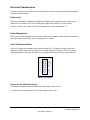
Serial Peripheral Interface
The four SPI signals are accessible using the 20-pin header JP7. The Data Out, Data In and Clock
signals are routed to both the JP7 header and an on-board temperature sensor. The SPI Chip Select
signal is selectable to either the JP7 header or to the temperature sensor using the 3-pin header JP1.
3
JP7
J5
1
U1
Figure 6 JP1 Header
Routing the SPI Chip Select Signal
To select the on-board temperature sensor, place the jumper on pins 1 and 2.
To route the Chip Select signal to JP7, place the jumper on pins 2 and 3.
Page 12
silex
Part Number 40183-101
SX-550 Evaluation Daughtercard
Hardware Configuration
Serial Ports
The two serial ports can be accessed with RS-232 signals, via the DB-9 connectors, or logic signals, via
the 10-pin headers.
The two logical serial port headers are located at JP2 and JP6. The serial ports provide four dedicated
signals and three optional signals. The optional signals are configured using jumpers. Table 5 details the
serial port signal descriptions.
Table 5 Logical Serial Port Signal Descriptions
Pin
1
Signal
DCD
Input/Output
Pin
Input
2
Signal
DSR
Enabled via header
Input/Output
Input
Enabled via header
3
RXD
Input
4
RTS
Output
5
TXD
Output
6
CTS
Input
7
DTR
Output
8
No
Connect
10
3.3V
Enabled via header
9
GND
All signals are 0 to 3.3 V logic signals.
To use header JP2, disable the RS-232 transceiver, U3, by placing a jumper on both JP8 pins.
To use header JP6, disable the RS-232 transceiver, U6, by placing a jumper on both JP9 pins.
Using the Optional Serial Signals
Signals GPIO 1 to 6 can be used as GPIO or Serial Port control signals DTR, DSR and DCD.
GPIO6
GPIO5
GPIO4
GPIO3
GPIO2
GPIO1
To configure signals DTR, DSR and DCD, place a jumper between JP4 and JP5 for that signal, as shown
in Figure 7.
JP3
JP4
DCD2
DSR2
DTR2
DCD1
DSR1
DTR1
JP5
Figure 7 Optional Serial Signals
SX-550 Evaluation Daughtercard
Hardware Configuration
silex
Part Number 40183-101
Page 13
To select the GPIO signals, place the jumper between JP3 and JP4. The GPIO signals are available at
JP7
Standard serial RS-232 signals are available on the DB-9 connectors J2 and J3 for serial ports 1 and 2,
as shown in Figure 8.
Figure 8 Serial Port DB-9 Connector
Table 6 DB-9 Pinouts for RS-232 Mode
DB-9
1
RS-232 Signal
DCD
Type
Input
Enabled via header
2
RXD
Input
3
TXD
Output
4
DTR
Output
Enabled via header
5
Ground
6
DSR
Input
Enabled via header
Page 14
7
RTS
Output
8
CTS
Input
9
NC
silex
Part Number 40183-101
SX-550 Evaluation Daughtercard
Hardware Configuration
General Purpose IO
The GPIOs, located on JP7, can be used for controlling or monitoring OEM functions. External pull-ups
are recommended for customization.
NOTE: GPIO 7 is fixed as a switch input and GPIO 8 is fixed as an LED output.
Table 7 General Purpose IO Signal Descriptions
Pin
Signal
Selectable
Pin
Signal
Via JP3
2
GPIO_2
Via JP3
4
GPIO_3
Via JP3
1
GPIO_1
3
3.3V
5
GPIO_4
Via JP3
6
GND
7
GPIO_5
Via JP3
8
GPIO_6
9
GPIO_7
10
3.3V
11
GPIO_8
12
GPIO_9
13
GPIO_10
14
GND
15
16
3.3V
17
18
19
20
Selectable
Via JP3
To use the first 6 GPIOs, place a jumper between JP3 and JP4 for the specific GPIO.
Table 8 General Purpose I/O Signal Description
Evaluation
Daughtercard
CN210
I/O
Drive High/Low
Description
GPIO
GPIO
1
2
I/O
6/6 mA
Set as input or output
2
3
I/O
6/6 mA
Set as input or output
3
4
I/O
6/6 mA
Set as input or output
4
5
I/O
6/6 mA
Set as input or output
5
6
I/O
6/6 mA
Set as input or output
6
7
I/O
6/6 mA
Set as input or output
7
48
I or I/O
6/6 mA
Switch input
6/6 mA
1 = off
0 = switch depressed
LED_1
1= off
0 = illuminated
8
49
SX-550 Evaluation Daughtercard
Hardware Configuration
O or I/O
silex
Part Number 40183-101
Page 15
Evaluation
Daughtercard
CN210
I/O
Drive High/Low
Description
GPIO
GPIO
9
50
O or I/O
6/6 mA
LED_2 or used as a GPIO
1= off
0 = illuminated
10
51
O or I/O
6/6 mA
LED_3 or used as a GPIO
1= off
0 = illuminated
43
O
6/6 mA
SPI chip select
44
O
6/6 mA
Ethernet PHY
1 = power down
0 = off (default)
47
O
6/6 mA
Ethernet PHY
1 = not reset (default)
0 = reset#
52
I
6/6 mA
PCI_LED2YP input
53
I
6/6 mA
PCI Power Management Event#
input
54
O
6/6 mA
PCI Clock
1 = clock off
0 = run# (default)
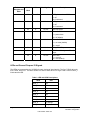
LEDs and General Purpose IO Signals
The LEDs are connected to the 10 GPIOs for easy viewing of signal activity. The first 7 GPIOs drive the
first 7 LEDs, D4 to D10. The last 3 GPIOs 8 to 10 drive LEDs D1 to D3. Logic 0 and 0 volts on GPIO_x
illuminates the LED.
Table 9 LED and GPIO Descriptions
GPIO
Page 16
LED
GPIO_1
D4
GPIO_2
D5
GPIO_3
D6
GPIO_4
D7
GPIO_5
D8
GPIO_6
D9
GPIO_7
D10
GPIO_8
D1 orange
GPIO_9
D2 yellow
silex
Part Number 40183-101
SX-550 Evaluation Daughtercard
Hardware Configuration
GPIO
GPIO_10
LED
D3 green
RS-232 Cable
The supplied DB-9 female-to-female null modem cable is wired as shown below.
Figure 9 RS-232 Cable Pinouts
Table 10 RS-232 Cable Pinout Description
Pin
Description
1
DCD (Data Carrier Detect) Input
6
DSR (Data Set Ready) Input
2
RxD (Receive Data) Input
3
TxD (Transmit Data) Output
4
DTR (Data Terminal Ready) Output
7
RTS (Request To Send) Output
8
CTS (Clear To Send) Input
5
Ground
Additional OEM Interface Signals
The output LED signals ORLED-, GRLED- and YELED- represent the state of the LEDs on the module.
Logic 0 indicates the LED is on, and Logic 1 indicates the LED is off. Buffers are recommended if LEDs
are to be driven on the end-user side.
The SWITCH signal is connected to a momentary pushbutton switch on the evaluation daughtercard and
is in the normally open position. Depressing the switch causes a short to ground. A 4.7 K-ohm pull-up
resistor to +3.3 VDC is connected. The module’s processor monitors this signal. The end-user can drive
or use open-collector to this signal to either logic level or can monitor this signal as an input.
SX-550 Evaluation Daughtercard
Hardware Configuration
silex
Part Number 40183-101
Page 17
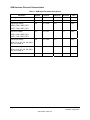
OEM Interface Electrical Characteristics
Table 11 OEM Signal Parameter Descriptions
Parameter
Symbol
Condition
Input high voltage
Vih
Input low voltage
Vil
Output high voltage
Voh
Ioh = 4mA
Vol
Iol = 4mA
Voh
Ioh = 6mA
Vol
Iol = 6mA
Ii
0 < Vin < 3.3v
Minimum
Maximum
2.0▼
Unit
Volts
0.7
2.4
Volts
Volts
UART0_TXD, UART0_RTS,
UART1_TXD, UART1_RTS
Output low voltage
0.4
Volts
UART0_TXD, UART0_RTS,
UART1_TXD, UART1_RTS
Output high voltage
2.4
Volts
GPIO 1 to 10, SPI, CS, SPI_SDO,
SPI_CLK, Reset_N
Output low voltage
0.4
Volts
+10
µA
GPIO 1 to 10, SPI, CS, SPI_SDO,
SPI_CLK, Reset_N
Input Leakage Current
Page 18
silex
Part Number 40183-101
-10
SX-550 Evaluation Daughtercard
Hardware Configuration
Chapter 4:
Using the SX-550 WLAN Module
The SX-550 WLAN module provides a dedicated host processor and an industry-leading network protocol
stack for connectivity to a traditional wired Ethernet or an 802.11a, b or g wireless local area network.
The module is easy to configure with several management options, including an internal web browser
interface and the Windows-based ExtendView configuration utility. In addition, the module’s internal
console can be accessed using TELNET or the serial port via a command line interface for sophisticated
diagnostics and configuration. It is also compatible with the SNMP MIBs I, II and has a proprietary MIB to
allow complete customization and monitoring.
The two circuit boards are 1.8 x 2.4-inch six-layer integrated design using surface-mounted components.
The module contains two I/O ports and three status LEDs that can be configured and programmed to
meet your functional requirements.
The compact form factor offers three through-holes allowing for flexible mounting options for
configurations, such as Ethernet and wireless versions. The Serial Port Emulator software allows for an
easy integration with existing PC applications.
A variety of power management options ensure very low power consumption during inactive periods.
Evaluation Module Connections
You can connect the SX-550 Evaluation Daughtercard to your LAN using wireless or wired Ethernet.
Using the Wireless Method
To use wireless method:
1. Verify the Ethernet cable is disconnected from the RJ-45 jack.
2. Connect the power supply plug to the SX-550 Evaluation Daughtercard.
3. Power on the power supply.
When the wireless connection connects with the access point, the yellow and green LEDs on the
module light up simultaneously. The lights blink during activity.
4. Continue to the Access silex Console Interface section.
silex
Part Number 40183-101
Page 19
Using the Wired Ethernet Method
To use wired Ethernet method:
1. Connect the Ethernet cable to the RJ-45 jack. This disables the wireless card.
2. Connect the power supply plug to the SX-550 Evaluation Daughtercard.
3. Power on the power supply.
When a link is established, the yellow and green LEDs on the module should begin blinking.
4. Continue to the Access silex Console Interface section.
Access silex Console Interface
You can access the silex Console Interface using a terminal program, such as Windows HyperTerminal.
To access HyperTerminal:
1. On a Windows computer, click START and select
Programs>Accessories>Communications>HyperTerminal. The Connection Description window
displays.
2. Type any name for the connection, then click OK. The Connect To window displays.
3. In the Connect Using list box, select a connection, then click OK. The default is COM1.
The COM Properties window displays.
4. On the Port Settings tab, select the settings shown in Table 12, then click OK.
Table 12 Port Settings
Parameter
Setting
Bits per Second
115200
Data Bits
8
Parity
None
Stop Bits
1
Flow Control
None
5. Press Return until the Local> prompt displays. No user name is necessary.
Now you are ready to enter console commands. For a list of the console commands, refer to
Appendix A:
Console Commands
Page 20
silex
Part Number 40183-101
Using the SX-550 WLAN Module
Generating Configuration Data
You can generate and view the configuration data using the pushbuttons on the module as described in
Table 13.
Table 13 Pushbutton Functions
Action
Depress for less than 5
seconds
Result
Generates configuration data output on Serial Port 1 of the module. It can
be viewed with a:
Terminal emulator, such as Windows HyperTerminal.
Serial device that displays ASCII characters
Test page if the module is connected to a serial printer
Depress for more than 5
seconds
Resets the module’s configuration to factory defaults (cold reset).
Depress for 3 seconds
during power up
Places the device into console configuration mode, which can be used to
configure the device using the module’s serial port on Serial Port 2.
Using the SX-550 WLAN Module
The unit automatically re-initializes after updating the configuration
memory.
silex
Part Number 40183-101
Page 21
Page 22
silex
Part Number 40183-101
Using the SX-550 WLAN Module
Chapter 5:
Accessing Configuration Parameters
The SX-550 is equipped with a default configuration that works with most serial-to-Ethernet and wireless
connections. You can modify the settings to suit your installation requirements by accessing:
•
ExtendView Utility
•
HTTP Pages Using Web Browser
•
Internal Command Console
If using Microsoft Windows operating systems, the ExtendView Utility is the recommended method of
configuring SX-550 modules on your network. If using UNIX operating systems, accessing the HTTP
pages using a web browser is the recommended method. If using a wireless SX-550 module, you can
use an Ethernet or wireless connection.
In addition, the SX-550 module is compatible with network management systems using SNMP MIBs I and
II protocol. The SX-550 module also supports a proprietary MIB that allows customization and monitoring.
Once you have installed and accessed the configuration software, continue to Chapter 4: Setting
Configuring Parameters for information on the configuration parameters.
Access ExtendView Utility
The 32-bit Windows-based TCP/IP utility, ExtendView Utility, is used to configure and manage the serial
port, network and wireless settings. You can view and configure all servers on the network simultaneously
or individually.
Table 14 describes the system requirements for installing the ExtendView Utility.
silex
Part Number 40183-101
Page 23
Table 14 ExtendView System Requirements
Component
Requirement -- VERIFY
Personal Computer
133 MHz or higher
Microsoft Windows Operating System
98SE, ME, 2000, XP or 2003
RAM Memory
64 MB or greater
Hard Disk Space
10 MB or greater
CD-ROM Drive
The developer’s kit CD contains the ExtendView Utility software. In addition, you can download the
software from the silex websites.
Installing ExtendView Utility
You can install the ExtendView Utility using the CD contained in your evaluation kit or accessing the
website.
To install ExtendView from CD:
1. Power on the personal computer, then access the network.
2. Connect the SX-550 module to the network using an Ethernet cable.
3. Power on the SX-550 module.
4. Insert the silex CD in the CD-ROM drive of the computer. The CD should display automatically.
If not, click the Windows Start menu, and select Run>Browse, then select the CD. The Browse
window displays.
5. Select Utilities, then ExtendView and select Setup. The Run window displays.
6. Click OK. The InstallShield Wizard displays. The InstallShield Wizard walks through the installation
process.
7. Once install is complete, remove CD from CD-ROM drive.
8. Continue to the Using ExtendView Utility.
NOTE: You can also install ExtendView from the silex web site at www.silexamerica.com.
Page 24
silex
Part Number 40183-101
Accessing Configuration Parameters
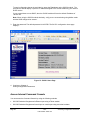
Using ExtendView Utility
To start ExtendView:
1. On the Windows main page, select Start/Programs.
2. Select silex technology, then ExtendView. The ExtendView Utility displays.
Figure 10 ExtendView Main Page
You must create a view to determine which servers on your network will be discovered and how that
information is displayed.
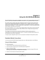
During the initial start up of the utility, the New View wizard begins.
3. To continue, click Next. To ext, click Cancel. The New View window displays.
Figure 11 ExtendView New View Window
4. In the View Name field, type any view name.
Select the protocol for locating and communicating with the servers.
To automatically create a new view with default settings, select the checkbox. View settings can be
modified at a later time.
Accessing Configuration Parameters
silex
Part Number 40183-101
Page 25
Figure 12 Create View with Default Settings
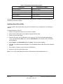
5. Click Finish. The ExtendView window displays a list of servers on the network.
6. Select the SX-550 module, then right click to display the menu.
The default SX-550 module name is SDSxxxxxx where xxxxxx is the last six digits of the MAC
address from the label located on the back of the SX-550 module.
Figure 13 ExtendView Window
Page 26
silex
Part Number 40183-101
Accessing Configuration Parameters
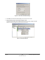
7. Select Configuration. The Server Configuration window displays as shown in Figure 14.
Figure 14 ExtendView Configuration Window
8. If no DHCP server exists, Extendview will prompt for a password before the configuration page
displays. If you are unsure of the IP address, check with your network administrator.
9. If using a wireless SX-550 module, configure the wireless settings by selecting country or region for
the region of operation.
NOTE: It may not be legal to operate the SX-550 module in a country or region other than the country
or region shown in the drop-down list. If your country or region is not listed, please check with your
local government agency.
Set the wireless mode as ad-hoc or infrastructure, SSID channel, and WEP encryption of the wireless
SX-550 module to the same configuration as the wireless network where you are communication. All
nodes must have the identical same settings to communicate with each other.
10. Continue to Chapter 6:
Setting Configuration Parameters.
Access HTTP Pages
You can manage and configure the SX-550 module using a standard web browser, such as Internet
Explorer or Mozilla Firefox.
NOTE: Prior to accessing the SX-550 module, you must configure the IP on both the computer and SX550 module.
To access the HTTP Pages:
1. Connect an Ethernet cable from your network hub to the SX-550 module.
2. Power on the computer and SX-550 module.
If the SX-550 module is connected to a serial device that cannot display or print ASCII characters,
then it is recommended that another serial device capable of displaying or printing ASCII characters
be temporarily connected to the SX-550 module. This ensures you can view the IP address assigned
by the DHCP server to the SX-550 module. The IP address must be different than the IP address
used by the computer.
Accessing Configuration Parameters
silex
Part Number 40183-101
Page 27
To send configuration data to the serial device, press the Test button on the SX-550 module. The
serial device should display or print the IP address assigned to the SX-550 module by your network
DHCP service.
If your network does not use DHCP, then the SX-550 module will have the default IP address of
192.0.0.192.
Note: When using the SX-550 module wirelessly, verify you are communicating using AdHoc mode
with the SSID configured as ‘serserv.’
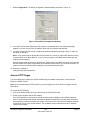
3. Enter the password. The default password is ACCESS. The SX-550 configuration home page
displays.
Figure 15 SX-550 Home Page
4. Continue to Chapter 6:
Setting Configuration Parameters.
Access Internal Command Console
You can access the Command Console by using the following methods:
•
SX-550 Evaluation Daughtercard’s Ethernet port using a Telnet session
•
SX-550 Evaluation Daughtercard’s serial port or console port using a terminal emulator
Page 28
silex
Part Number 40183-101
Accessing Configuration Parameters
•
SX-550 Web Page Configuration
Using Telnet Session
To access using telnet:
1. Connect the SX-550 module’s Ethernet cable to the host computer.
2. On the Windows main page, select Start>Run. The Run window displays.
3. Type the following command, then click OK.
telnet x.x.x.x
where x.x.x.x is the IP address of the SX-550 module
The default port is 23.
4. When the connection is established, press Enter. The # prompt displays.
5. Type the password (default is ACCESS), then press Enter. The password will not echo on your
screen.
6. Press Enter until the Local> prompt displays. No user name is necessary. You can begin configuring
the SX-550 module.
Continue to Chapter 6:
Setting Configuration Parameters.
NOTE: For the list of console commands, refer to Appendix A:
Console Commands.
Using Terminal Emulator through the Serial Port
To access using the serial port:
1. Attach the null modem serial cable from the DB9 serial port on the SX-550 module to the COM port
on the computer.
2. If you do not wish to cycle the SX-550 module’s power to enter the console mode, continue to
step 3.
To enter the console mode by cycling the SX-550 module’s power, press and hold the SX-550
module’s test button for at least three seconds while powering the device.
The SX-550 module will begin initializing.
3. Start a terminal emulation program, such as Windows HyperTerminal, by selecting
Start/Programs/Communications/HyperTerminal. The Connection Description window displays.
4. Type a name for the connection, then click OK. The Connect To window displays.
5. In the Connect Using list box, select a connection, then click OK. The default is COM1.
The COM Properties window displays.
6. On the Port Settings tab, select the settings shown in Table 15, then click OK.
Accessing Configuration Parameters
silex
Part Number 40183-101
Page 29
Table 15 Port Settings
Parameter
Setting
Bits per Second
115200
Data Bits
8
Parity
None
Stop Bits
1
Flow Control
None
7. Press Return to display the Local prompt.
To display the IP address, type Local> sh ip.
The console displays the boot information, such as IP Address, Subnet Mask, IP Gateway, LPD
Banner, LPD Retries, Boot Tries, Boot Method, Maximum Window, Timeout, Keepalive, Service, Port
and TCP Port.
NOTE: If you manage and configure the SX-550 module using the embedded HTTP pages, you will
need to configure the IP address in both the computer and SX-550 module.
8. Continue to Chapter 6:
Setting Configuration Parameters.
Using AT Modem Commands
The Evaluation Daughtercard contains a wireless serial device firmware with optional data filter for
configuring using AT style modem commands. This feature allows devices with an existing AT command
interface to configure the unit, if the AT commands can be properly modified. You must be familiar with
the general operation of AT commands. Note that AT command processing is not enabled by default. Use
the command SET PORT S1 FILTER AT to enable this feature.
All commands begin with AT and are terminated by a new line unless noted below. While standard AT
commands are defined to be 40 characters or less (not including the AT), the server accepts commands
of up to 80 characters.
Standard AT Commands Supported
The following standard AT commands are interpreted by the device server. The data channel must be in
the command mode for commands to be recognized. The data channel will be in command mode upon
power up or reset.
There are two operating modes for the unit when the AT command option is enabled. In command mode,
data received from the serial port is passed to the AT command processor, and responses are returned to
the serial port. No data is sent to any network application, and any data received from the network is
ignored. In data mode, data from the serial port passes to the network application, and vice versa. This
is equivalent to the normal serial port operating mode without the AT command option.
Table 16 describes the AT Commands. Table 17 details the Extended AT Commands that allow the
configuration of the network server operating parameters.
Page 30
silex
Part Number 40183-101
Accessing Configuration Parameters
Any AT command received, except the listed commands, are acknowledged with OK status. This allows
existing modem applications to transmit commands without causing an error. These include AT<X>n,
but not currently AT&<X>n, AT%<X>n, AT\<X>n, where <X> is a letter.
Table 16 AT Commands
Parameter
Command
Description
Enter Command mode
<delay>+++<delay>
If the string +++ is seen in data mode, with no
characters sent for 1 second before or after, then
command mode is entered.
Initiate Connection
Command
ATD <destination>
Standard modem dialing command, redefined to
initiate an internet connection to a remote computer.
Indicates the IP address of the target, and optionally
the TCP port number to use for connection. The T or
P option (ATDT or ATDP) can be present and has
no effect.
If present, the IP address must be exactly 12 decimal
digits with 3 for each byte of the address.
If no IP address is given, then the ecable destination
address defined for the port is used.
If the destination TCP port is defined, it is separated
from the IP address by a '#' character, and is 1 to 5
decimal digits.
If TCP port is defined, the ecable destination port
defined for the serial port is used. If the destination
port is 0, the standard Telnet port (23) is used.
If the destination string ends with a semicolon, the
server remains in the command mode, not the data
mode, once a connection is made.
In command mode data is not passed from the
remote computer, so data could be lost if the unit
stays in command mode.
If the connection cannot be attempted, NO CARRIER
status is returned. If the connection attempt fails, NO
ANSWER status is returned.
If the connection succeeds, CONNECT status is
returned.
Echo control
ATEn
If n=0, commands are not echoed.
If n=1, subsequent commands will be echoed.
The default, upon unit reset, is for no echo (ATE0).
Disconnect
ATHn
If n=0, any connection to a remote host is dropped.
Other value of n is ignored.
Return to data mode
ATOn
Exits command mode and places the serial port in
the data mode.
All subsequent data is sent to the network
application, if connected, until an enter command
mode sequence is received. Any value of n is
ignored, if present.
Accessing Configuration Parameters
silex
Part Number 40183-101
Page 31
Parameter
Quiet mode
Command
ATQn
Description
If n = 1, no result codes are returned.
If n = 0, result codes are returned to the local device.
0 is the reset default value.
Verbose mode
ATVn
If n = 0 and not in quiet mode, result codes are
returned in numerical form.
If n = 1, results are returned as text. 1 is the reset
default value.
Table 17 Extended AT Commands
Parameter
Console pass through
Command
AT#C<string>
Description
Passes the string to the server configuration console.
The string can be any valid console command. Refer
to your server documentation for console commands
available on your unit.
Since this command does not follow the normal AT
command format of <command><number>, it must
be the last command on the line unless the next
command is a '#' command. All characters up to the
end of line or a '# will be considered part of the
console command.
If console quiet mode is not is enabled, then the
response will be the standard console task response.
Example:
AT#Cset nw ssid silex#Csave
Console Quiet mode
AT#Qn
If n = 0, a response to a #C command is given.
If n = 1, the response is not provided. The default
after reset is 1.
Response Codes
Table 18 details the response codes for codes other than #C commands.
Table 18 Response Codes
Numeric Code
Page 32
Description
0
OK
2
No Carrier
4
Error
5
Connect
8
No Answer
silex
Part Number 40183-101
Accessing Configuration Parameters
Chapter 6:
Setting Configuration Parameters
The SX-550 module is equipped with a default configuration that works with most serial-to-Ethernet and
wireless connections. You can modify the settings to suit your installation requirements.
ExtendView is the recommended method for setting configuration parameters. However, regardless of the
method to access the configuration parameters, the method for modifying the parameters is virtually
identical.
Factory Default Settings
Table 19 displays the configuration parameter descriptions and settings with the default settings indicated
in a separate column.
Table 19 Factory Default Settings
Parameter
Description
Settings
Default Setting
Character
Bits per character
7, 8
8
Flow
Flow control
None, Xon, Xoff,
CTS/RTS
None
Parity
Parity
None, Even, Odd, Mark,
Space
None
Speed
Baud rate of bits per second
300, 600,1200, 2400,
3600, 4800, 7200,
9600, 14400,19200,
38400, 57600, 76800,
115200, 230400,
460800, 921600
9600
115200 – console
port default
Stop
Stop bits per character
1, 2
1
Mode
Line mode or serial port protocol
232, 422, 485, 485HD,
Disabled
232
Ecable
E-cable mode for TCP connections
Enable, Disable
Disable
Ecaddr
E-cable destination IP address
Set by user
N/A
Econn
E-cable connection attempt time
1-255 seconds
30 seconds
silex
Part Number 40183-101
Page 33
Parameter
Ecport
Description
E-cable destination IP port number
Settings
Default Setting
9100 or set by user
9100
Restoring Factory Default Settings
The factory default settings can restored at any time. Simply perform a cold reset by pressing and holding
the module push button for more than five seconds.
Modify Basic Settings
To establish communication between the SX-550 module and a serial device, the settings must be
identical for both devices.
Changing Serial Settings
The serial settings, such as mode and baud rate or speed for both the SX-550 module and serial device
must be identical in order to communicate. You can change the serial settings using ExtendView
(recommended), the web browser interface, or the SX-550 module’s internal configuration console.
To change serial settings:
1. Using ExtendView, web browser interface or internal command console, click the Output Port tab.
The Output Port window displays.
Figure 16 Output Port Tab
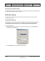
2. Click Serial Settings. The Serial Settings window displays.
Page 34
silex
Part Number 40183-101
Setting Configuration Parameters
Figure 17 Serial Settings Window
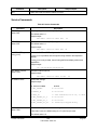
3. Configure the serial settings, as defined in Table 20.
Table 20 Serial Setting Parameters
Parameter
Setting
Mode
Sets the line mode or serial port protocol.
Character Bits
RS-232 provides an interface between data terminal equipment and
data communications equipment employing serial binary data
interchange over a wired connection with a maximum range of 50
feet (16.5 meters).
RS-422 provides a data transmission system using balanced
differential signals or voltages to send serial binary data over a
wired connection with a maximum range of 4,000 feet (1.2 km).
Sets the line mode or serial port protocol.
Values are:
232 (default), 422, Disabled
Sets the bits per character
Values are:
8 (default), 7
Sets parity checking to detect any errors in transmission.
Values are:
None (default), Even, Odd, Mark, Space
Sets the baud rate for measuring for data transmission speed
Values are:
9600 (default), 115200 (console port default) 300, 600,1200, 2400,
3600, 4800, 7200, 14400,19200, 38400, 57600, 76800, 230400,
460800, 921600
Parity
Speed
Setting Configuration Parameters
silex
Part Number 40183-101
Page 35
Parameter
Stop Bits
Setting
Sets the number of extra bits that mark the end of a unit of
transmission.
Values are:
1 (default), 2
Flow Control
Manages data flow between computers or devices so data can be
handled at an efficient pace.
Values:
None (default), Xon, Xoff, CTS/RTS
4. To accept changes, click OK.
To cancel, click Cancel.
For additional help, click Help.
NOTE: You can configure the same settings using the Web Page configuration. Simply log in using the
SX-550 IP address and select the I/O ports. For the changes to become effective, submit the changes,
then reset the device.
Modifying TCP/IP Settings
You can modify the TCP/IP settings using ExtendView (recommended), the web browser interface or the
SX-550 module’s internal configuration console.
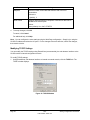
To modify TCP/IP settings:
1. Using ExtendView, web browser interface or internal command console, click the TCP/IP tab. The
TCP/IP window displays.
Figure 18 TCP/IP Window
Page 36
silex
Part Number 40183-101
Setting Configuration Parameters
2. Verify the settings, as defined in Table 21.
Table 21 TCP/IP Settings
Parameter
IP Address
Resolution
Setting
Sets the exchanges among network interfaces connected to an
Ethernet media segment and maps IP address to Ethernet
addresses, Media Access Control (MAC) addresses and hardware
addresses.
The Set Permanent radio button sets the IP address permanent.
The IP address must follow the format XXX.XXX.XXX.XXX, where
each XXX is a number between 0 and 255.
The Use Network Protocol Select radio button determines which IP
address at power up.
Subnet Mask
Default Gateway
WINS Server
Use DHCP to
Locate WINS
Server
Sets the address of the subnet mask
The subnet mask must follow the format XXX.XXX.XXX.XXX,
where each XXX is a number between 0 and 255. The default
subnet mask is 0.0.0.0. The server interprets a subnet mask of
0.0.0.0 or 255.255.255.255 as no subnet mask specified.
Sets the default gateway, if your network is attached to other
networks
Sets the Windows Internet Naming Service (WINS) address
Values are set by user.
Uses the automatic location feature in ExtendView to locate the
WINS servers.
3. To change the Telnet/HTTP password, click Telnet/HTTP Password. The Change Password window
displays.
Figure 19 Change Password Window
Type the new password in the New Password field, then in the Verify Password field.
Click OK to change the password or click Cancel to exit.
4. Click Advanced TCP/IP. The Advanced TCP/IP Configuration window displays.
Setting Configuration Parameters
silex
Part Number 40183-101
Page 37
Figure 20 Advanced TCP/IP Configuration Window
5. Configure the settings, as defined in Table 22.
Table 22 TCP/IP Configuration Settings
Parameter
Setting
TCP Connection
Timeout
Sets the timeout and reset values for the TCP connections
Unsolicited ARP
Blocks or broadcasts unsolicited ARP
DNS
Sets the DNS addresses
6. To accept changes, click OK.
To cancel, click Cancel.
For additional help, click Help.
NOTE: You can configure the same settings using the Web Page configuration. Simply log in using the
SX-550 IP address and select the I/O ports. For the changes to become effective, submit the changes,
then reset the device.
Page 38
silex
Part Number 40183-101
Setting Configuration Parameters
Configure Simple Network Management Protocol
The SX-550 module contains a Simple Network Management Protocol (SNMP) agent that collects and
stores management information for network managers using standard SNMP commands. The
management information is referenced as a hierarchically organized database called a Management
Information Base (MIB).
To prevent naming conflicts, all of the manageable features of all products from all vendors are arranged
in a single tree structure. Each vendor of SNMP equipment has an exclusive section of the MIB Tree .
Each branch of the MIB Tree has a number and name. The path from the top of the tree down to the point
of interest forms the name of that point. A name created in this way is known as an Object ID or OID.
Table 23 describes the messages used to communicate between the network manager and the SNMP
agent, as defined in RFC 1157. Each SNMP message must contain a Community Name, which is used
like a password. The default Community name for the SX-550 module is PUBLIC.
Table 23 SNMP Commands
Command
GET
Description
Retrieves management information for a specific managed object contained in the
agent.
The GET message must contain the OID for the specified object. The response is a
GET-RESPONSE message containing either the current value of the requested
object, or an indication as to why the request failed.
GET NEXT
Retrieves management information from a non-specific managed object.
The GET NEXT contains either a complete OID or a fragment of an OID. The
response is a GET-RESPONSE message containing either the OID and data of the
item immediately right of the specified OID in the tree or an indication as to why the
request failed.
GET
RESPONSE
This is the information sent back from the unit in response to the GET, GET NEXT
command.
SET
Requests a change to the value of a specified object.
The response is a GET-RESPONSE message with either an indication that the
requested change had been made or with an indication as to why the request failed.
TRAP
Sends a one-way notification from the agent to the manager that a significant event
has occurred. This is the only message initiated by the SNMP agent.
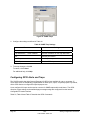
To set the SNMP Traps:
1. Using ExtendView, web browser interface or internal command console, click SNMP Traps tab. The
SNMP Traps window displays.
Setting Configuration Parameters
silex
Part Number 40183-101
Page 39
Figure 21 SNMP Traps
2. Configure the settings as defined in Table 24.
Table 24 SNMP Trap Settings
Parameter
Setting
Protocol
Sets the protocol
Trap Destination – TCP/IP Address
Sets the IP address for the trap destination
Port
Sets the port location
Port Traps
Sets the port traps
GPIO Traps
Sets the GPIO traps
3. To accept changes, click OK.
To cancel, click Cancel.
For additional help, click Help.
Configuring GPIO Alerts and Traps
The SX-550 module has eight General Purpose I/O (GPIO) lines available for use on connector J7.
These GPIO lines are individually programmable for either input, output, or special purpose. By default,
all the GPIO lines are configured for special purpose use.
Lines configured for input can be used as a source for SNMP traps and/or email alerts. The GPIO
direction, trigger settings, and email/web page message strings are configured from the Internal
Configuration Console interface.
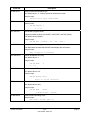
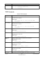
Table 25, Table 26 and Table 27 describe the GPIO Commands.
Page 40
silex
Part Number 40183-101
Setting Configuration Parameters
Table 25 GPIO Commands
Command
Description
SHOW GPIO DIR
Shows current direction setting of GPIO lines
SET GPIO DIR IN|OUT <GPIO #>
Sets GPIO Direction In/Out
GPIO # = {1|2|3|4|5|6|7|8}
Example:
Local> show gpio dir
GPIO Direction
-------------1 [OUT]
2 [IN]
3 [IN]
4 [IN]
5 [SPCL]
6 [SPCL]
7 [SPCL]
8 [SPCL]
Local> set gpio dir in 1
Local> set gpio dir out 2
Local> show gpio dir
GPIO Direction
-------------1 [IN]
2 [OUT]
3 [IN]
4 [IN]
5 [SPCL]
6 [SPCL]
7 [SPCL]
8 [SPCL]
Setting Configuration Parameters
silex
Part Number 40183-101
Page 41
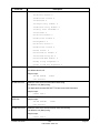
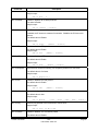
Command
Description
SHOW GPIO SPECIAL
Shows functional mode of GPIO lines
SET GPIO SPECIAL ENA/DIS
<GPIO #>
Sets GPIO special function mode
GPIO # = {1|2|3|4|5|6|7|8}
Example:
Local> show gpio special
GPIO Special Functions
----------------------GPIO #1 is special
GPIO #2 is normal
GPIO #3 is special
GPIO #4 is special
GPIO #5 is special
GPIO #6 is special
GPIO #7 is special
GPIO #8 is special
Local> set gpio special disable 1
Local> set gpio special enable 2
Local> show gpio special
GPIO Special Functions
----------------------GPIO #1 is normal
GPIO #2 is special
GPIO #3 is special
GPIO #4 is special
GPIO #5 is special
GPIO #6 is special
GPIO #7 is special
GPIO #8 is special
Table 26 GPIO Trigger Commands
Command
Description
SHOW GPIO TRIGger
Shows current GPIO trigger conditions and
corresponding TRAP number
SET GPIO TRIGger <trigger state> <GPIO #>
Sets GPIO Trigger Condition
Trigger state = {1| 0 | dis}
1: 0 to 1 transition
GPIO # = {1|2|3|4|5|6|7|8}
0:1 to 0 transition
Dis: Disable
Example:
Local> set gpio trig 1 1
Page 42
silex
Part Number 40183-101
Setting Configuration Parameters
Command
Description
Local> set gpio trig 0 2
Local> show gpio trig
GPIO Trigger Conditions
----------------------trig if GPIO #1 is 1 <Trig #1>
trig if GPIO #2 is 0 <Trig #2>
GPIO #2 is set for OUTPUT
GPIO #3 is set for OUTPUT
Table 27 GPIO Transmit Commands
Command
SHOW GPIO TRANsmit
SHOW GPIO TRANsmit <trig #>
Description
Displays email or web page strings assigned to GPIO
triggers
trig # = 0 to 7
SET GPIO TRANsmit <trig #> <string>
Sets transmit string corresponding to trigger condition
trig # = 0 to 7
DEL GPIO TRANsmit <trig #>
Deletes transmit string corresponding to trigger condition
trig # = 0 to 7
Example:
Local> show gpio tran
Trig #
-----0:
1:
Email String
-----------GPIO #1 is 1
GPIO #2 is 1
Local> set gpio tran 0 your email text msg here
Local> show gpio tran
Trig #
-----0:
1:
Email String
-----------your email text msg here
GPIO #2 is 1
Local> show gpio tran 1
1: GPIO #1 is 1
Setting Configuration Parameters
silex
Part Number 40183-101
Page 43
Configuring Serial Port Monitor Alert and Trap Configuration
The SX-550 module can be configured to scan and compare the data received on the serial port to userdefined strings. A match with a string can be a source for SNMP traps and/or email alerts.
The match strings and corresponding email or web page message strings are configured from the Internal
Configuration Console interface.
Table 28 describes the Monitor Alert and Trap Configuration Commands.
Table 28 Port Monitor Alert Commands
Command
Description
SHOW PORT S1 TRIGMON
Shows strings and index numbers being monitored
SET PORT S1 TRIGMON <trig #> <string>
Assigns a string to be monitored on the serial port
Example:
Local> show port s1 trigmon
Index #
------
Monitor String
--------------
Local> set port s1 trigmon 0 trigger on seeing this string
Local> show port s1 trigmon
Index #
-----0:
Page 44
Monitor String
-------------trigger on seeing this string
silex
Part Number 40183-101
Setting Configuration Parameters
Table 29 TRIGMON Commands
Command
Description
SHOW PORT S1 TRIGXMT
Shows email or web page strings associated with
TRIGMON index numbers
SET PORT S1 TRIGXMT <index #> <string>
Assigns email or web page string to specified
TRIGMON index number
Index # = 0 to 7
Example:
Local> show port s1 trigxmt
Index #
-----0:
Xmit String
--------------xmit string 0
<<< default msg string
Local> set port s1 trigxmt 0 The trigger string was seen!
Local> show port s1 trigxmt
Index #
-----0:
Xmit String
--------------The trigger string was seen!
Setting Configuration Parameters
silex
Part Number 40183-101
Page 45
Chapter 7: Designing with the SX-550
OEM Header Interface
Table 30 describes the OEM header interface pinout for the SX-550 WLAN Module. Table 31 describes
the OEM interface signal descriptions. All input and output signals, except the differential signals, are 0 to
3.3 V logic signals.
Table 30 OEM Header Interface Pinout
Pin
Signal
Pin
Signal
1
TPRX+
2
TPTX+
3
TPRX-
4
TPTX-
5
GPIO_7
6
GPIO_8
7
AVDD
8
+3.3VDD
9
UART0_RXD
10
GPIO_9
11
UART0_TXD
12
GPIO_10
13
GND
14
+3.3VDC
15
UART0_RTS
16
UART0_CTS
17
UART1_RTS
18
UART1_CTS
19
GND
20
GND
21
UART1_TXD
22
UART1_RXD
23
GND
24
RESET_N
25
SPI_CS
26
SPI_CLK
27
+3.3VDC
28
GND
29
GPIO_1
30
SPI_SDO
31
GPIO_2
32
SPI_SDI
33
+3.3VDC
34
GND
35
GPIO_3
36
GPIO_4
37
GND
38
GND
39
GPIO_5
40
GPIO_6
silex
Part Number 40183-101
Page 46
Table 31 OEM Interface Signal Description
Signal
Pin
Type
Description
TPRX+, TPRX-
1,3
Differential Output
Ethernet Transmit Data primary
TPTX+, TPTX-
2,4
Differential Input
Ethernet Receive Data primary
AVDD
7
Power
Ethernet Power Output to
transformer center tap
UART0_RXD
9
Input
Serial Port 1 Receive Data
UART0_TXD
10
Output
Serial Port 1 Transmit Data
UART0_RTS
15
Output
Serial Port 1 Request To Send
UART0_CTS
16
Input
Serial Port 1 Clear to Send
UART1_RXD
22
Input
Serial Port 2 Receive Data
UART1_TXD
21
Output
Serial Port 2 Transmit Data
UART1_RTS
17
Output
Serial Port 2 Request To Send
UART1_CTS
18
Input
Serial Port 2 Clear to Send
GPIO1, GPIO2,
GPIO3, GPIO4,
GPIO5, GPIO6,
GPIO7, GPIO8,
GPIO9, GPIO10
29, 31, 35, 36,
39, 40, 5, 6,
10, 12
Input/Output
General Purpose Input/Output
Signals 1-10, User defined
SPI_CS
25
Output
Serial Peripheral Interface Chip
Select (high-true)
SPI_SDO
30
Output
Serial Peripheral Interface Data
Out
SPI_SDI
32
Input
Serial Peripheral Interface Data In
SPI_CLK
26
Output
Serial Peripheral Interface Clock
RESET_N
24
Output
Power-on Reset (low true)
+3.3VDC
8, 14, 27, 33
Power
Power VCC Input
GND
13, 19, 20, 23,
28, 34, 37, 38
Power
Power Ground
The SX-550 module uses the 40-pin 1.27 mm pitch male header by Gradconn part number BB02-BK401K03-3040B0.
Mating 4.6 mm tall female headers are:
Gradconn Interconnect part number: BB02-CL402-K03-000000
www.gradconn.com
Samtec part number: SFMC-120-02-S-D
www.samtec.com
Imperial Connector Systems part number: B2B-401-B-C
www.imperial-connect.com
E-tec Interconnect part number: BS2-040-H450-11/11AT
www.e-tec.ch
Designing with the SX-550
silex
Part Number 40183-101
Page 47
Antenna Connectors
The SX-550 WLAN Module has two SMT Ultra-miniature coaxial connectors (U.FL). Table 32 describes
the connector types.
For single antenna use, connect to the main antenna connector, as shown in Figure 22 .
For diversity antenna use, connect to both the main and auxiliary connectors.
Figure 22 Main and Auxiliary Antenna Connectors
Table 32 Antenna Connector Types
Parameter
Description
Connector Type
SMT Ultra-miniature Coaxial Connector
(U.FL)
Connector Size
Maximum height of 2.4 to 2.5 mm
Nominal Characteristic Impedance
50 Ohm
Rated Voltage
60 V AC (rms)
Rated Frequency
DC to 6 GHz
Contact Resistance
Center: 20 mOhm maximum
Outside: 10 mOhm maximum
500 MOhm @ 100 VDC minimum
Insulation Resistance
Antenna Cable Plug
iPEX 90 degrees plug with right angle
receptacle and cable diameter at 1.32
mm
For the antenna connector, the SX-550 module uses a Hirose U.FL-R-SMT (CL331-0471-0-01) ultra
miniature coaxial receptacle.
Mating plugs are:
Hirose part number: U.FL-LP-066
www.hirose.co.jp
Page 48
silex
Part Number 40183-101
Designing with the SX-550
Ethernet PHY
The Ethernet PHY is located on the processor card. The manufacturer is Davicom and the part number is
DM9161AE. For additional information on the layout of the transformer and RJ-45 jack, refer to the
Davicom website at www.davicom.com.tw.
2
1:1
1
7
2
3
4
4
40-pin
OEM
Header
Transformer
5
1:1
6
7
1
7
3
RJ46
8
Figure 23 Circuit Diagram with Transformer
Transformer Specification
Table 33 and Table 34 detail the magnetic specifications and manufacturer sources. Magnetics that meet
these requirements are available from various magnetic manufacturers. You should test and qualify the
magnetic specifications prior to use in your application. The magnetics listed are electrical equivalents;
however, may not be pin-to-pin equivalents.
Table 33 10/100M Magnetic Specifications
Parameter
Values
Units
Test Conditions
TX/RX Turns Ratio
1:1 CT/1:1
Inductance
350
µH minimum
Insertion Loss
1.1
dB maximum
1 to 100 MHz
Return Loss
-18
dB minimum
1 to 30 MHz
-14
dB maximum
30 to 60 MHz
-12
dB minimum
60 to 80 MHz
Differential to Common Mode
Injection
-40
dB maximum
1 to 60 MHz
-30
dB minimum
60 to 1000 MHz
Transformer Isolation
1500
V
Designing with the SX-550
silex
Part Number 40183-101
Page 49
Table 34 10/100M Magnetics Manufacturers
Manufacturer
Part Number
Pulse Engineering
PE-68515, H1102
YCL
PH163112, PH163539
Halo
TG110-050N2, TG110-LC50N2
Bel Fuse
S358-5999-W2
Bothhand
TS6121CX, LU1S041CX, TS61210,
I6ST8515, 16ST1066
GTS
FC-618SM
General Purpose I/O Interface
Table 35 details the GPIO interface. The first 10 GPIOs are user-configurable as either input or output.
GPIOs 48 to 51 have default uses, but can be user configured.
Table 35 GPIO Interface
40-Pin
Header
GPIO
I/O
Drive High/Low
Description
CN210
GPIO
1
2
I/O
6/6 mA
Can be set as input or output
2
3
I/O
6/6 mA
Can be set as input or output
3
4
I/O
6/6 mA
Can be set as input or output
4
5
I/O
6/6 mA
Can be set as input or output
5
6
I/O
6/6 mA
Can be set as input or output
6
7
I/O
6/6 mA
Can be set as input or output
7
48
I or I/O
6/6 mA
Switch input
1 = off
0 = switch depressed
8
49
O or I/O
6/6 mA
LED_1
1= off
0 = illuminated
9
50
O or I/O
6/6 mA
LED_2 or used as a GPIO
1= off
0 = illuminated
10
51
O or I/O
6/6 mA
LED_3 or used as a GPIO
1= off
0 = illuminated
Page 50
43
O
6/6 mA
silex
Part Number 40183-101
SPI chip select
Designing with the SX-550
40-Pin
Header
GPIO
I/O
Drive High/Low
Description
CN210
GPIO
44
O
6/6 mA
Ethernet PHY
1 = power down
0 = off (default)
47
O
6/6 mA
Ethernet PHY
1 = not reset (default)
0 = reset#
52
I
6/6 mA
PCI_LED2YP input
53
I
6/6 mA
PCI Power Management Event# input
54
O
6/6 mA
PCI Clock
1 = clock off
0 = run# (default)
Power
Power is input to the SX-550 WLAN Module using the 40-pin OEM Header. Required voltage is 3.3VDC ±
5%.
At full power, the current consumption is 950mA.
In low power mode with the processor clock at 60MHz and the SX-550 in power save mode, the current
consumption is 370mA.
Designing with the SX-550
silex
Part Number 40183-101
Page 51
Chapter 8:
Product Specifications
Table 36 Product Specifications
Component
Specifications
Model
SX-550 WLAN Module
Processor
Cavium NITROX Soho CN210
RAM Memory
16 Mbytes SDRAM.
Processor Speed
167 MHz at full power
Interfaces Supported
Serial: RS-232 w/ external transceivers
Ethernet: 10/100BaseT using RJ-45 8-wire jack
Serial Peripheral Interface
Table 37 Radio Performance Specifications
Parameter
Specifications
Radio Emission Type
Complies with IEEE 802.11a, b, g, h and j Direct Sequence Spread
Spectrum (DSSS) physical layer.
Operating Frequency
2.412 GHz ∼ 2.484 GHz ISM band
5.15 GHz ∼ 5.35 GHz ISM band
5.725 GHz ∼ 5.825 GHz ISM band
Data Modulation Type
Orthogonal Frequency Division Multiplexing (OFDM)
Complementary Code Keying (CCK)
Differential Quadrature Phase Shift Keying (DQPSK)
Differential Binary Phase Shift Keying (DBPSK)
Channel Number
IEEE 802.11b and g: Channels 1 to 11 and 12 to 14
IEEE 802.11a: Channels 36, 40, 44, 48, 52, 56, 60, 64, 149, 153, 157
and 161
silex
Part Number 40183-101
Page 52
Parameter
Specifications
Data Rate
54 Mbps with fallback rates of 48, 36, 24, 18, 12, 11, 9, 6, 5.5, 2, and 1
Mbps
Security
WEP Encryption: 64/128 bits
TKIP, AES
Media Access Protocol
Carrier Sense Multiple Access with Collision Avoidance (CSMA/CA)
with ACK architecture, 32 bits MAC-layer.
Antenna Connector Type
2 SMT ultra-miniature coaxial connectors
Operating Voltage
3.3 VDC ± 5%
Bus Interface
Proprietary 70-Pin
Antenna Port Impedance
50 ohm
Channel Switching Speed
260 µsec
LO Settling Time
61 µsec
Receiver Noise Figure
6.0/6.7 dB (typ/max) 2.4Ghz
9.2/9.6 dB (typ/max) 5Ghz
Transmit Output Power (Production Specification)
Test Conditions: Supply Voltage (Vcc) = 3.3V, Ambient Temperature = 25ºC
Frequency Range
(Bands)
Modulation
Rate
Minimum
Output
Typical
Output
Maximum
Output
Power
(dBm)
Power
(dBm)
Power
(dBm)
Transmitter Power
1 Mbps
14
15.5
20.5
Output low band
(802.11b)
2 Mbps
14
15.5
20.5
5.5 Mbps
14
15.5
20.5
11 Mbps
14
15.5
20.5
Transmitter Power
6 Mbps
15.5
17
21.5
Output low band
(802.11g)
9 Mbps
15.5
17
21.5
12 Mbps
14
15.6
20
18 Mbps
14
15.6
20
24Mbps
13
14.3
19
36 Mbps
13
14.3
19
48 Mbps
10
11.6
16
54 Mbps
10
11.6
16
6 Mbps
15
16.1
21
Transmitter
Designing with the SX-550
silex
Part Number 40183-101
Page 53
Power Output high
band (802.11a)
9 Mbps
15
16.1
21
12 Mbps
14
15.6
20
18 Mbps
14
15.6
20
24Mbps
13
14.8
19
36 Mbps
13
14.8
19
48 Mbps
8.5
10.9
15
54 Mbps
8.5
10.9
15
Receiver Sensitivity (Production Specification)
Test Conditions: Supply Voltage (Vcc) = 3.3V, Ambient Temperature = 25ºC
Frequency
Range
(Bands)
Modulation
Rate
Transmitter
Power
Output low
1Mbps
(8%PER)
band
(802.11b)
(8%PER)
2 Mbps
5.5 Mbps
Minimum
Receiver
Sensitivity
Typical
Receiver
Sensitivity
Maximum
Receiver
Sensitivity
(dBm)
(dBm)
(dBm)
-92
-94
/
-90
-92
/
-89
-91
/
-85
-87
/
-89
-91
/
-87
-89
/
-86
-88
/
-83
-85
/
-79
-81
/
-75
-77
/
-70
-72
/
(8%PER)
11 Mbps
(8%PER)
Transmitter
Power
Output low
6 Mbps
(10%PER)
band
(802.11g)
(10%PER)
9 Mbps
12 Mbps
(10%PER)
18 Mbps
(10%PER)
24 Mbps
(10%PER)
36 Mbps
(10%PER)
48 Mbps
Page 54
silex
Product Specifications
(10%PER)
54 Mbps
-68
-70
/
-88
-90
/
-86
-88
/
-85
-87
/
-82
-84
/
-78
-80
/
-74
-76
/
-69
-71
/
-67
-69
/
(10%PER)
Transmitter
Power
Output high
6 Mbps
(10%PER)
band
(802.11a)
(10%PER)
9 Mbps
12 Mbps
(10%PER)
18 Mbps
(10%PER)
24 Mbps
(10%PER)
36 Mbps
(10%PER)
48 Mbps
(10%PER)
54 Mbps
(10%PER)
TCP Port Connections
The SX-550 module supports port connections over TCP/IP using raw TCP ports only. Table 38
describes the TCP ports allocations.
Table 38 TCP Port Connections
Port
Destination Device
3001
RS-232
9100
RS-232
9200
RFC 2217
Designing with the SX-550
silex
Part Number 40183-101
Page 55
Appendix A:
Console Commands
The following tables describe the console commands available from the internal command console.
Access the command console through the serial port (J1), console port (JP1) or Ethernet port using a
Telnet session.
Wireless and Network Security Commands
The following group of commands configures network parameters.
Table 39 Network Commands
Command
SH NW
Description
Displays summary network information
Sample output:
WiFi Mode = INFRASTRUCTURE
WiFi SSID: silex
Speed = 11
Regulatory Domain = 704
WiFi FW Ver = 1F 1.7.1
AP density = LOW
TTLS is Disabled
WEP is Disabled
Link DOWN
SET NW
AUTHtype
Sets wireless authentication type
The default value is Open System
Sample output:
SET NW AUTHtype [OPEN |SHARED | TTLS | LEAP | WPA-PSK]
silex
Part Number 40183-101
Page 56
Command
SH NW AUTH
Description
Shows wireless authentication type
The default value is 11. Value is ignored in Infrastructure mode.
Sample output:
Authentication type= OPEN SYSTEM
SET NW CHannel
Sets WLAN ad-hoc channel number
Sample output:
SET NW CHannel n
n = 1-11
SET NW ENC
Sets WLAN Encryption Mode.
Supported modes are None, 64 bit WEP, 128 bit WEP, and TKIP (WPA).
The default value is Disable.
Sample output:
SET NW ENC
SH NW ENC
[DIsable | 64 | 128 | TKIP ]
Shows the wireless encryption mode
The deprecated command SH NW WEP also displays this information.
Sample output:
WiFi encryption is Disabled
SET NW KEY#
Selects WLAN WEP key entry
The default value is 1.
Sample output:
SET NW KEY#
n
n = 1-4
SET NW KEYVAL
Sets the WLAN WEP key entry to the hex value
The default value is null.
Sample output:
SET NW KEYVAL <key>
key=10 or 26 hex characters
SET NW MOde
Sets WLAN mode
The default value is Infra
Sample output:
SET NW MOde
<mode>
[Infrastructure | Ad-Hoc]
SH NW MODE
Console Commands
Shows wireless operating mode
Sample output:
Wifi mode = AD-HOC (802.11)
silex
Part Number 40183-101
Page 57
Command
Description
SH NW RADio
Shows the selected radio mode of operation
Sample output:
Radio mode is 802.11b
SET NW SPeed
Sets maximum WLAN speed
The default value is 11.
Sample output:
SET NW SPeed
n
n = 1,2,5.5 or 11
SH NW SPEED
Show the maximum wireless data speed in megabits per second
Sample output:
Speed = 11
SET NW SSid
Sets WLAN SSID
The default value is printer.
Sample output:
SET NW SSid
<name>
User defined
CL NW SSid
Clears SSID value and allows the server to connect to any AP.
Sample output:
CL NW SSid
SET NW BSsid
Sets WLAN BSSID to connect to a specific access point’s mac address
Sample output:
SET NW BSsid <value>
User defined (MAC Address)
CL NW BSsid
Clears BSSID value and allows the server to use SSID, not a specific AP
Sample output:
CL NW BSsid
SET NW RTS
Sets WLAN RTS threshold
The default value is 2432.
Sample output:
SET NW RTS
n
n = 1-3000
SH NW RTS
Shows wireless RTS threshold
Sample output:
Wifi RTS Threshold = 2432
SH NW STATS
Shows network I/O statistics
Sample output:
WiFi statistics:
TX Unicast frames: 0
TX Multicast frames: 0
Page 58
silex
Part Number 40183-101
Console Commands
Command
Description
TX Fragments: 0
TX Unicast octets: 0
TX Multicast octets: 0
TX Deferred: 0
TX Single retry frames: 0
TX Multiple retry frames: 0
TX Retry limit exceeded: 0
TX Discards: 0
RX Unicast frames: 0
RX Multicast frames: 0
RX Fragments: 0
RX Unicast octets: 0
RX Multicast octets: 0
RX FCS errors: 0
RX Discards no buffer: 0
TX Discards wrong SA: 0
RX Discards WEP undecr: 0
RX Msg in msg fragments: 0
RX Msg in Bad msg fragments: 0
SET NW CERTCN
Sets EAP Common Name
The default value is null.
Sample output:
SET NW CERTCN
<name>
User defined
SH NW CERTCN
Shows the value of first common name check string
The default is null (blank) string.
The deprecated command SH NW TTCN also returns this information.
Sample output:
Common name 1
SET NW
CERTCN2
Sets second EAP Common Name
Sample output:
SET NW CERTCN2
<name>
User defined
SH NW CERTCN2
Shows the value of the second common name check string
The default is null (blank) string.
Sample output:
Common name 2
Console Commands
silex
Part Number 40183-101
Page 59
Command
SET NW
CERTEXP
Description
Sets EAP Certificate Exponent value
The default value is 10001 Hex.
Sample output:
SET NW CERTEXP
<exponent>
User defined
SH NW CERTEXP
Shows the value of the certificate exponent
The deprecated command SH NW TTEXP also returns this value
Sample output:
65537 (10001h)
SET NW
CERTKEY
Sets EAP root key
Sample output:
SET NW CERTKEY
SET NW ID
<key value>
Sets authentication User ID
This can include the realm separated by @.
The default value is anonymous.
Sample output:
SET NW ID
SH NW ID
<user id>
Shows the value of the authentication ID, including realm, if applicable
The default realm is a null (blank) string.
The deprecated command SH NW TTID also returns this data.
Sample output:
anonymous@somewhere
SET NW PW
Sets the password for the 802.1x EAP authentication, if enabled
The default value is anonymous.
Sample output:
SET NW PW
SET NW INAP
<password>
Sets EAP inner-authentication protocol
The default value is PAP.
Sample output:
SET NW INAP
SH NW INAP
[PAP|MSCHAP_V2]
Shows the inner authentication mode
The deprecated command SH NW TTAP also returns this data.
Sample output:
Authentication protocol = PAP
SET NW REALM
Sets the realm portion of the 802.1x EAP authentication ID
This value can also be set with the ID command.
The default value is null.
Page 60
silex
Part Number 40183-101
Console Commands
Command
Description
Sample output:
SET NW REALM
SH NW REALM
<realm>
Shows the realm associated with the authentication ID, if applicable.
The default value is null (blank) string.
The deprecated command SH NW TTRE also returns this data.
Sample output:
somewhere
SET NW
WPAGROUPSH
NW WPAAUTO
Enable or disable WPA group key mode.
If enabled, group keys can be used for data link encryption.
The default value is disabled.
Sample output:
SET NW WPAGROUP [ENABLE | DISABLE]Shows state of WPA auto connect flag
Sample output:
WPA-AUTO Enabled
SH NW
WPAGROUPSET
NW WPAGROUP
Shows state of the allow WPA group keys flag
Sample output:
WPA-GROUP DisabledEnable or disable WPA group key mode.
If enabled, group keys can be used for data link encryption.
The default value is disabled.
Sample output:
SET NW WPAGROUP [ENABLE | DISABLE]
SET NW
WPAPSKSH NW
WPAGROUP
Sets WPA PSK pass phrase or hex key.
This value is only used if the authentication mode is WPA-PSK. The argument to
this command is either a pass phrase of 8 to 63 characters or exactly 64 hex
characters representing the 256 bit PSK value.
Sample output:
SET NW WPAPSK <key>Shows state of the allow WPA group keys flag
Sample output:
WPA-GROUP Disabled
SET NW
WPATRACESET
NW WPAPSK
Sets WPA trace level.
This command is for diagnostic purposes only.
The default value is 0 or disabled.
Sample output:
SET NW WPATRACE nnSets WPA PSK pass phrase or hex key.
This value is only used if the authentication mode is WPA-PSK. The argument to
this command is either a pass phrase of 8 to 63 characters or exactly 64 hex
characters representing the 256 bit PSK value.
Sample output:
SET NW WPAPSK <key>
Console Commands
silex
Part Number 40183-101
Page 61
Command
SET NW
WPATRACE
Description
Sets WPA trace level.
This command is for diagnostic purposes only.
The default value is 0 or disabled.
Sample output:
SET NW WPATRACE nn
Port Commands
Table 40 Port Commands
Command
SH PORT
Description
Shows port parameters
Sample output:
Port
Q-Size
*S1
XON/XOFF RS232
SET PORT
Type
0
Attributes
serial
115200 N 8 1
Sets port parameters.
The commands are dependent on the port type.
CLEAR PORT S1
JOB
Aborts the active job on the port.
If the remote host is connected, additional data received will be discarded.
Sample output:
CL PORT S1 JOB
SET PORT S1
FLOW
Sets serial port flow control to NONE, XON/XOFF, CTS, or DSR
The default value is none.
Sample output:
SET PORT S1 FLOW <flow>
SET PORT S1
PARITY
Sets serial port parity to NONE, EVEN, ODD, MARK, or SPACE
The default value is none.
Sample output:
SET PORT S1 Parity <parity>
SET PORT S1
SIZE
Sets data bits on the serial port
The default value is 8.
Sample output:
SET PORT S1 Signal [7 | 8]
SET PORT S1
SPeed
Sets serial port baud rate. Options for BAUD are 300, 600, 1200, 2400, 7200, 9600,
19200, 38400, 57600, 115200, 230400, and 460800
The default value is 115200.
Page 62
silex
Part Number 40183-101
Console Commands
Command
Description
Sample output:
SET PORT S1 SPEED <baudrate>
SET PORT S1
STOP
Sets serial port stop bits per character
The default value is 1.
Sample output:
SET PORT S1 STOP [1 | 2]
Server Information Commands
Table 41 Server Information Commands
Command
SET SERVEr
DEscription
SET SERVEr NAme
Description
Sample Output
Sets server description string
Sample output:
SET SERVEr DEscription
<description-string>
Sets server node name
The default value is TWC_xxxxxx, where xxxxxx are the last 6 hex digits of the
MAC address.
Sample output:
SET SERVEr
SET SNMP GETCOMM
NAme
Gets community name
The default value is public.
Sample output:
SET SNMP GETCOMM
SET SNMP JETADmin
<name>
<string>
Enables or disables JetAdmin compatibility
The default value is enabled.
Sample output:
SET SNMP JETADmin [ ENable |
SET SNMP
SETCOMM1
DIsable]
Sets community 1 name
The default value is internal?
Sample output:
SET SNMP SETCOMM1 <string>
SET SNMP
SETCOMM2
Sets community 2 name
The default value is Pass.
Sample output:
SET SNMP SETCOMM2 <string>
SET SNMP CONtact
Sets system contact string
The default value is null.
Sample output:
SET SNMP CONtact
Console Commands
<string>
silex
Part Number 40183-101
Page 63
Command
SET SNMP LOCation
Description
Sample Output
Sets system location string
The default value is null.
Sample output:
SET SNMP LOCation <string>
SH SERIAL
Displays serial number of the unit
Sample output:
Serial number is 9047595
SH SERVEr
Shows server parameters
Sample output:
Serial Server Serial # 9047595
Address: 00-40-17-8A-0E-2B
Number: 0
Identification:
Name: TWC_8A0E2B
Network Server
Enabled Characteristics:
Link DOWN
SH SERVEr CO
SH SNMP
Shows server network statistics
Sample output:
Seconds Since Zeroed: 163
Frames Sent,1 Collision: 26
Bytes Received:72950
Frames Sent, 2+Collision: 5
Bytes Sent:18726
Send Failures: 0
Frames Received:752
Send Failure Reasons: 0
Frames Sent: 181
Receive Failures:
Multicast Bytes Rcv'd:64474
Receive Failure Reasons: 1
Multicast Bytes Sent: 2406
Unrecognized Destination: 0
Multicast Frames Rcv'd:626
Data Overrun: 0
Multicast Frames Sent:11
User Buffer Unavailable:0
Frames Sent, Deferred:2014
System Buffer Unavailable:1
503
Shows state of SNMP protocol enable
Sample output:
SNMP is Enabled
SH VErsion
Shows firmware version of print server
Protocols supported: NetBIOS SNMP TCP/IP EMail DHCP
Sample output:
serial server
Firmware Ver. 4.19 (2004.10.31)
Boot Ver. 1.4
16Mbit Flash
Page 64
silex
Part Number 40183-101
Console Commands
Command
Zero
Description
Sample Output
Clears and resets the network statistic counters
Service Commands
Table 42 Service Commands
Command
SET SERVI <service
name> BOT
Description
Sets beginning of transmission (BOT) string index for service
The default value is 1.
Sample output:
SET SERVI <service name> BOT
SET SERVI <service
name> EOT
Sets end of transmission (EOT) string index for service
The default value is 1.
Sample output:
SET SERVI <service name> EOT
SH SERVI STRings
[string_num]
nn
nn
Defines the BOT and EOT strings used in services
If string_num is provided, then the specific string definition and expansion
display.
If string_num is not provided, then all string definitions display without their
expansions.
Sample output:
10: \FF\04\FF\05\FF\06\FF\08
SET SERVI <service
name> FIlter
Sets filter index for service
Sample output:
SET SERVI <service name> FIlter
SH SERVI FILters
Shows filter settings
Sample output:
#
SET SERVI <service
name> FMS
nn
Service Name
Filter
1 TWC_FFFFFF
0: No Filter
2 BINARY_P1
0: No Filter
3 TEXT_P1
1: Text Substitution m= LF, r= CRLF
4 TWC_FFFFFF_P1_4
0: No Filter
5 TWC_FFFFFF_P1_5
0: No Filter
6 TWC_FFFFFF_P1_AT
4: PostScript Tagged Binary
Sets filter 1 text replacement match string index.
If the index is zero, the default string of <LF> (line feed) is used.
The default value is 0.
Console Commands
silex
Part Number 40183-101
Page 65
Command
Description
Sample output:
SET SERVI <service name> FRM
SET SERVI <service
name> FRS
nn
Sets filter 1 text replacement replace string index.
If the index is zero, the default string of <CRLF> (carriage return-line feed) is
used.
The default value is 0.
Sample output:
SET SERVI <service name> FRS
SET SERVI <service
name> IP
nn
Enables or disables IP based jobs such as lpd, raw tcp and ftp, on the service
The default value is enabled for service 1 and 2, disabled for all others.
Sample output:
SET SERVI <service name> IP
SET SERVI <service
name> NAme
[ENable | DIsable]
Changes service name
The default value varies by service
Sample output:
SET SERVI <service name> NAme
SET SERVI <service
name> POrt
Sets output port associated with a service
The default value is S1.
Sample output:
SET SERVI <service name> POrt
SET SERVI <service
name> PRIority
<newname>
<portname>
Sets priority for service for multiple service transmissions simultaneously
The default value is 10.
Sample output:
SET SERVI <service name> PRIority nn
SH SERVI PRI
[service_num]
Shows priority of service.
SET SERVI <service
name> RECeive
Sets receive only mode for a service
If service_num is not provided, the priority of all services is listed.
This option is required only for host applications that do not operate properly
if data is received from the serial device.
The default value is disabled.
Sample output:
SET SERVI <service name> RECeive
DIsable]
SET SERVI <service
name> TCP
Sets raw TCP port for service
If port number is 0, raw TCP is disabled on service.
The default value is 9100 for service 1, 3001 for service 2.
Sample output:
SET SERVI <service name> TCP
SH SERVI SUMmary
Page 66
[ENable |
nn
Shows the basic parameters for a specific service. If service_num is not
silex
Part Number 40183-101
Console Commands
Command
Description
[service_num]
provided, parameters for all services are displayed.
The command SH SERVI displays the same data as SHOW SERVI SUM.
String Commands
Table 43 String Commands
Command
SET STRing
Description
Set service string table entry
String 1 to11 cannot be set or changed.
Sample output:
SET STRing <string #> ”value”
CL STRing
Clears the service string table entry
Sample output:
CL STRing <string #>
SH STRing
[string_num]
Defines the BOT and EOT strings used in services
If string_num is provided, then the specific string definition and expansion are
displayed. If string_num is not provided, then all string definitions are displayed
without their expansions.
Sample output:
1:
2: \1BE
3: \04
4: \1B%-12345X
5: @PJL
6: ENTER LANGUAGE=
7: PCL\0A
8: POSTSCRIPT\0A
9: \FF\04\FF\05\FF\06\FF\07
10: \FF\04\FF\05\FF\06\FF\08
11: \0C
SH FILters
Shows the filters that can modify a job stream
Sample output:
Console Commands
#
Filter
0
No Filter
1
Text Substitution
2
AppleTalk
silex
Part Number 40183-101
Page 67
Command
Description
3
Text to PostScript
4
PostScript Tagged Binary
5
DC1 Special
TCP/IP Commands
Table 44 TCP/IP Commands
Command
SET IP ACcess
Description
Allows or prevents access to a block of remote addresses
The default value is empty list.
Sample output:
SET IP ACcess [EN | DI | ALL] aa.bb.cc.dd {MAsk
ee.ff.gg.hh]
SET IP RANge
Allows or prevents access to a range of remote addresses
The default value is empty list.
Sample output:
SET IP RANge [EN | DI | ALL] aa.bb.cc.dd {MAx
ee.ff.gg.hh]
SH IP ACcess
Displays current access list settings
Sample output:
All hosts permitted access
SET IP ADdress
Sets server IP address
The default value is 192.0.0.192
Sample output:
SET IP ADdress aa.bb.cc.dd
SET IP ARP
ENable
Enables or disables setting of IP address with an ARP packet
The default value is Enable.
Sample output:
SET ARP [ENable | DIsable]
SET IP BAnner
Enables or disables printing of job banner on LPD jobs
The default value is Disable.
Sample output:
SET IP BAnner [ENable | DIsable]
SET IP CHKSUM
Enables or disables verification of IP checksum on received packets
The default value is Enable.
Sample output:
SET IP CHKSUM [ENable | DIsable]
SET IP BOot
Page 68
Sets number of tries for each enabled IP boot method, if not set to static
silex
Part Number 40183-101
Console Commands
Command
Description
The default value is 3.
Sample output:
SET IP BOot
SET IP ENable
n
Enables or disables all IP based protocols
The value is Enable.
Sample output:
SET IP [ENable | DIsable]
SET IP FTIme
Sets IP timeout
If enabled, the IP timeout is measured in seconds. If disable, the IP timeout is in
minutes.
The default value is Disable.
Sample output:
SET IP FTIme
[ENable | DIsable]
SET IP FTP
Enables or disables FTP protocol
The default value is Enable.
Sample output:
SET IP FTP
[ENable | DIsable]
SET IP HTTP
Enables or disables HTTP protocol
The default value is Enable.
Sample output:
SET IP HTTP
SET IP KEepalive
[ENable | DIsable]
Sets interval in minutes for sending TCP keepalive packets on a connection
The default value is 5 minutes.
Sample output:
SET IP KEepalive n
SET IP LPD
Enables or disables the LPD protocol
The default value is Enable.
Sample output:
SET IP LPD
SET IP MEthod
[ENable | DIsable]
Sets method of getting IP address
The default value is Auto.
Sample output:
SET IP MEthod
SET IP PIng
[ AUTO | BOOTP | RARP | DHCP | STATIC ]
Sends IP ping packets to test connection to remote host
Sample output:
SET IP PIng
SET IP PRObe
aa.bb.cc.dd
Enables or disables TCP connection probes
The default value is Disable.
Console Commands
silex
Part Number 40183-101
Page 69
Command
Description
Sample output:
SET IP PRObe
SET IP RARp
[ENable | DIsable]
Enables setting of default router and/or subnet mask based on RARP IP address
set
The default value is 0.
Sample output:
SET IP RARp
nn
nn: 0=both 1=no subnet,
SET IP REtry
2=no router, 3=neither
Enables or disables LPD retry on incomplete job
The default value is Disable.
Sample output:
SET IP REtry
SET IP ROuter
[ENable | DIsable]
Sets default router address
The default value is 0.0.0.0.
Sample output:
SET IP ROuter
SET IP SUbnet
aa.bb.cc.dd
Sets IP subnet mask
The default value is 0.0.0.0.
Sample output:
SET IP SUbnet
SET IP TCP
aa.bb.cc.dd
Enables or disables the raw TCP 9100 protocol
The default value is Enable.
Sample output:
SET IP TCP
SET IP TELnet
[ENable | DIsable]
Enables or disables Telnet protocol
The default value is Enable.
Sample output:
SET IP TELnet [ENable | DIsable]
SET IP TFTP
Enables or disables TFTP protocol
The default value is Enable.
Sample output:
SET IP TFTP
SET IP TImeout
[ENable | DIsable ]
Sets TCP inactivity timeout.
If fast timeout is enabled, the timeout is calculated as seconds.
If fast timeout is disabled, the timeout is calculated as minutes.
The default value is 1 minute.
Sample output:
Page 70
silex
Part Number 40183-101
Console Commands
Command
Description
SET IP TImeout
SET IP WIndow
n
Sets TCP maximum window size in bytes
The default value is 10240.
Sample output:
SET IP WIndow
SH IP
nn
Shows TCP/IP related parameters
The default value is
Sample output:
IP is enabled
IP address
192.0.0.192
Boot tries
3
Subnet mask
0.0.0.0
Boot method
AUTO
IP Gateway
0.0.0.0
Max window
10240
(set manually)
LPD banner
disabled
LPD retries are disabled
Service
Timeout
1 min
Keepalive
5 min
Port
TCP port
xxxxxx_S1_A
S1
9100
xxxxxx_S1_B
S1
3001
Power Configuration Commands
Table 45 Power Configuration
Command
SET POWER LEVEL n
Description
Sets the power save mode. High power is for fastest throughput,
low power is for lowest power consumption.
Set POWER LEVEL 0, 1 or 2
0 = High Power
1 = Medium Power
2 = Low Power
Firmware Update
Table 46 Firmware Update
Command
SET LOAd
ENable
Console Commands
Description
Sets the firmware to perform a soft reset and enter the server boot program after the
next Exit command.
silex
Part Number 40183-101
Page 71
Command
Description
This command is used for diagnostic purposes only.
The default value is Disable.
Sample output:
SET LOAd (ENable | DIsable ]
SET LOAd HOst
Sets the node name of the Netware boot host.
This command is used for diagnostic purposes only.
The default value is null>\
Sample output:
SET LOAd HOst
SET LOAd IP
<name>
Sets source computer IP address for TFTP get operation.
The default value is 0.0.0.0.
Sample output:
SET LOAd IP
SET LOAd
SOftware
aa.bb.cc.dd
Sets filename on host for TFTP get update
Sample output:
SET LOAd SOftware
SET LOAd TFTP
<filename>
Initiates firmware update using TFTP get operation.
The TFTP server address must be set using SET LOAd IP and the filename using
SET LOAd SOftware. The server will reset after the firmware update is completed.
Sample output:
SET LOAd TFTP
SET LOAd
XModem
Initiates firmware update using the XModem protocol on the serial console
SH LOAd
Shows the firmware update parameters
The server will reset after the firmware update is completed.
Sample output:
SET LOAd XModem
Sample output:
Firmware load is disabled
Load Host IP
= 0.0.0.0
Software file
= xxxx.bin
Load Host Name =
Page 72
silex
Part Number 40183-101
Console Commands
Miscellaneous Commands
Table 47 Miscellaneous Commands
Command
Description
SET DEFAULT
Set parameters to factory defaults
EXIT
This command exits the current configuration console session.
SH FATal
Shows fatal error log, if fatal errors exist.
CL FATal
Clears the fatal error log
INIT
Instructs the server to execute a soft reset when the next exit command is
executed.
SET PAssword
Sets the server access (read) password
SET POWERON
Sets Power on delay
SH POWERON
Displays Power on delay in seconds
SET PROTect
Sets update password to the string given.
CL PROTect
Sets update password to <null>.
SAVE
Saves the current configuration to non-volatile memory.
Without this command, the configuration is not saved unless an EXIT
command is performed.
SH TEst
Sends the configuration data via ASCII to the serial port
UNPROTECT
If an update password has been defined (SET PROTECT), this command
enters the password to allow configuration items to be modified.
After entering this command, the server will prompt for the update
password. If entered properly, the user will then be able to execute SET
commands to modify the server configuration. This lasts only until the
console session is terminated with an EXIT command.
Help Commands
For help, simply enter HELP preceding the command. The correct syntax and a brief description of the
commands will display.
For example, when inquiring for various commands to display specific IP parameters, type HELP SHOW
IP.or for commands to change specific wireless/network security parameters, type HELP SET NWRK.
Console Commands
silex
Part Number 40183-101
Page 73
Appendix B:
Engineering Drawings
Antenna Cable Assembly
Figure 24 Antenna Cable Assembly
Table 48 Electrical Performance
Parameter
Value
Impedance
50 ohms
Frequency Range
0 to 5 GHz
Working Voltage
6O VAC maximum
Dielectric Withstanding Voltage
20 DVAC maximum
Insulator Resistance
500 megohms minimum
silex
Part Number 40183-101
Page 74
Figure 25 Electrical Specifications for Antenna
Figure 26 Connector Specifications
Engineering Drawings
silex
Part Number 40183-101
Page 75
Table 49 Electrical Specifications
Parameter
Page 76
Value
Antenna Type
Dipole Swivel Antenna
Frequency Range
2.4 to 5.8 GHz
Impedance
50 Ohms
Gain
2.4 GHz < 2.0 dBi
5.8 GHz < 0 dBi
VSWR
≤ 2.0
Admitted Power Radiation
Omni
Polarization
Vertical
Electrical Length
¼ n Dipole
Standard Connector
SMA male reverse
silex
Part Number 40183-101
Engineering Drawings
silex technology america, Inc.
www.silexamerica.com
Part Number 40183-101