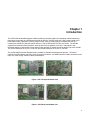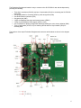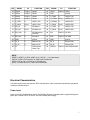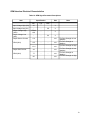
1
SX-570/SX-580 Embedded Intelligent Module with Evaluation Board Developer’s Reference WA100540XA Copyright © 2013 Silex Technology, Inc. All rights reserved. July, 2013 Silex Technology, Inc. SPECIFICALLY DISCLAIMS THE IMPLIED WARRANTIES OF MERCHANTABILITY AND FITNESS OF THIS PRODUCT FOR A PARTICULAR PURPOSE. Silex shall not be liable for any errors contained in this manual or for any damages resulting from loss of use, data, profits, or any incidental or consequential damages arising from the use of SILEX products or services. The information contained in this documentation is subject to change without notice. Information and descriptions contained herein are the property of Silex. Such information and descriptions may not be copied, disseminated, or distributed without the express written consent of Silex. This publication is subject to change without notice. The software embedded in this SX-570/580 module includes the Linux operating system. Linux and certain other software programs used in the SX-570/580 are licensed under GNU GPL compatible Free Software Licenses. In compliance with these licenses, you can obtain the relevant source code at no charge by contacting Silex at [email protected]. Trademarks All company or product names referenced in this document may be trademarks or registered trademarks of their respective owners. Silex Technology, Inc. www.silex.jp Contents About This Reference Guide........................................................................................................................................................ 1 Safety Precautions................................................................................................................................................................... 1 Emissions Disclaimer............................................................................................................................................................... 1 Chapter 1 Introduction.................................................................................................................................................................................. 2 Chapter 2 Installing the Evaluation Daughtercard........................................................................................................................................ 3 Verify Development Kit Contents ............................................................................................................................................ 5 Connecting the Evaluation Daughtercard to PC....................................................................................................................... 5 Monitoring Module Status........................................................................................................................................................ 6 OEM Interface.......................................................................................................................................................................... 6 Electrical Characteristics.......................................................................................................................................................... 7 Power Input.......................................................................................................................................................................... 7 Serial Ports........................................................................................................................................................................... 8 RS-232 Cable....................................................................................................................................................................... 9 Using the GPIO Special Functions..................................................................................................................................... 10 I/O Header.......................................................................................................................................................................... 10 USB Host Port .................................................................................................................................................................. 12 Ethernet Port...................................................................................................................................................................... 12 Additional OEM Interface Signals....................................................................................................................................... 12 Serial Peripheral Interface.................................................................................................................................................. 12 OEM Interface Electrical Characteristics............................................................................................................................ 13 Chapter 3 Configuring the SX-570/580....................................................................................................................................................... 14 Basic Configuration Requirements......................................................................................................................................... 14 Initial Wireless Setup.............................................................................................................................................................. 15 Configuration Methods........................................................................................................................................................... 15 Using a Web Browser to Configure the SX-570/580.............................................................................................................. 16 Using the Internal Command Console to Configure the SX-570/580.....................................................................................19 Chapter 4 Using the SX-570/580 with Your Application............................................................................................................................. 22 Linux Programmability............................................................................................................................................................ 22 Customizing the SX-570/580 User Interface.......................................................................................................................... 22 Raw TCP connection............................................................................................................................................................. 23 RFC 2217 Remote Modem Control Support.......................................................................................................................... 23 ECable Mode......................................................................................................................................................................... 24 Print Server Mode.................................................................................................................................................................. 25 Console Mode Switching........................................................................................................................................................ 25 Access Point Mode................................................................................................................................................................ 26 Bridge Mode........................................................................................................................................................................... 29 Smart Wireless Setup............................................................................................................................................................ 32 Chapter 5 Interfacing the SX-570/580 to the OEM Device......................................................................................................................... 37 OEM Interface........................................................................................................................................................................ 44 Installing the SX-570/580....................................................................................................................................................... 45 Antenna Connectors.............................................................................................................................................................. 45 General Purpose I/O Interface............................................................................................................................................... 46 Chapter 6 Advanced Configuration............................................................................................................................................................ 47 Factory Default Settings......................................................................................................................................................... 47 Restoring Factory Default Settings..................................................................................................................................... 48 Modifying TCP/IP Settings ................................................................................................................................................... 48 Configuring the General Purpose I/O (GPIO) Lines............................................................................................................... 50 Chapter 7 Product Specifications............................................................................................................................................................... 54 TCP Port Connections........................................................................................................................................................... 56 Appendix A Wireless Security Configuration................................................................................................................................................. 57 Appendix B Console Commands.................................................................................................................................................................. 61 1. Introduction and command console access information..................................................................................................... 61 2. Network Commands........................................................................................................................................................... 62 2.1 SH NW ...................................................................................................................................................................... 62 2.2 SET NW CHannel........................................................................................................................................................ 62 2.3 SET NW DISCONN..................................................................................................................................................... 63 2.4 SET NW DIVErsity....................................................................................................................................................... 63 2.5 SET NW MOde............................................................................................................................................................ 63 2.6 SET NW RADio........................................................................................................................................................... 64 2.7 SH NW RATE.............................................................................................................................................................. 64 2.8 SET NW RTS.............................................................................................................................................................. 64 2.9 SH NW SQ.................................................................................................................................................................. 65 2.10 SET NW SSid............................................................................................................................................................ 65 2.11 DEL NW SSid............................................................................................................................................................ 65 3. Wireless Network Security Commands.............................................................................................................................. 66 3.1 SET NW AUTHtype..................................................................................................................................................... 66 3.2 DEL NW CERT............................................................................................................................................................ 66 3.3 SET NW ENC.............................................................................................................................................................. 67 3.4 SET NW ID ................................................................................................................................................................ 67 3.5 SH NW WLLIST........................................................................................................................................................... 67 3.6 SET NW KEY#............................................................................................................................................................ 68 3.7 SET NW KEYNUM...................................................................................................................................................... 68 3.8 SET NW KEYVAL........................................................................................................................................................ 68 3.9 SET NW PW ............................................................................................................................................................. 68 3.10 SET NW PEAPGTC.................................................................................................................................................. 68 3.11 SET NW PEAPMSchap............................................................................................................................................ 69 3.12 SET NW PEAPV0..................................................................................................................................................... 69 3.13 SH NW PKCERT....................................................................................................................................................... 69 3.14 SET NW PKPASS..................................................................................................................................................... 69 3.15 SET NW REALM .................................................................................................................................................... 70 3.16 SET NW SSCCITY.................................................................................................................................................... 70 3.17 SET NW SSCCOMNAME.......................................................................................................................................... 70 3.18 SET NW SSCCOUNTRY........................................................................................................................................... 70 3.19 SET NW SSCGEN.................................................................................................................................................... 71 3.20 SET NW SSCKEYSIZE............................................................................................................................................. 71 3.21 SET NW SSCORGNAME.......................................................................................................................................... 71 3.22 SET NW SSCORGUNIT............................................................................................................................................ 71 3.23 SET NW SSCSTATE................................................................................................................................................. 72 3.24 SET NW WPAPSK.................................................................................................................................................... 72 4. Wireless Network Roaming Control................................................................................................................................... 73 4.1 SET NW BGSCAN...................................................................................................................................................... 73 4.2 SET RM....................................................................................................................................................................... 73 4.3 SET RM SCAN NORM................................................................................................................................................ 73 4.4 SET RM SCAN LOW................................................................................................................................................... 73 4.5 SET RM THRESH LOW.............................................................................................................................................. 74 4.6 SET RM THRESH CRITical......................................................................................................................................... 74 5. Wireless to Ethernet Client Bridging Configuration............................................................................................................ 75 5.1 SET NW BRACCess.................................................................................................................................................... 75 5.2 SET NW BRCLADDR.................................................................................................................................................. 75 5.3 SET NW BRIDGE........................................................................................................................................................ 75 5.4 SH NW BRIDGE.......................................................................................................................................................... 75 5.5 SET NW BRSTATIC.................................................................................................................................................... 76 6. Smart Wireless Setup........................................................................................................................................................ 77 6.1 Smart Wireless Setup for station................................................................................................................................. 77 6.1.1 SET NW SWSPINCODE....................................................................................................................................... 77 6.1.2 SET NW SWSPBC................................................................................................................................................ 77 6.1.3 SET NW SWSPBC NOWAIT................................................................................................................................ 77 6.1.4 SET NW SWSPIN ................................................................................................................................................ 77 6.2 Smart Wireless Setup for AP....................................................................................................................................... 78 6.2.1 SET NW SWSPINCODE....................................................................................................................................... 78 6.2.2 SET NW APSWSPBC........................................................................................................................................... 78 6.2.3 SET NW APSWSPBC NOWAIT............................................................................................................................ 78 6.2.4 SET NW APSWSPIN............................................................................................................................................ 78 6.2.5 SET NW APSWSCCAncel.................................................................................................................................... 78 6.2.6 SH NW APSWSCSTatus...................................................................................................................................... 78 7. Port Commands................................................................................................................................................................. 79 7.1 Serial Port Commands................................................................................................................................................. 79 7.1.1 SH PORT.............................................................................................................................................................. 79 7.1.2 SET PORT S1 CH................................................................................................................................................. 79 7.1.3 SET PORT S2 COnsole........................................................................................................................................ 79 7.1.4 SET PORT S1 CONSTR...................................................................................................................................... 80 7.1.5 SH PORT S1 CONSTR........................................................................................................................................ 80 7.1.6 SET PORT S1 DTR.............................................................................................................................................. 81 7.1.7 SET PORT S1 FLOW .......................................................................................................................................... 81 7.1.8 CLEAR PORT S1 JOB.......................................................................................................................................... 81 7.1.9 SET PORT S1 LATENCY.................................................................................................................................... 81 7.1.10 SET PORT S1 PARITY....................................................................................................................................... 82 7.1.11 SET PORT S1 SPeed......................................................................................................................................... 82 7.1.12 SH PORT S1 STAtus.......................................................................................................................................... 82 7.1.13 SET PORT S1 STOP.......................................................................................................................................... 82 7.2 ECable Port Commands.............................................................................................................................................. 83 7.2.1 SET PORT S1 ECABLE....................................................................................................................................... 83 7.2.2 SH PORT S1 ECABLE......................................................................................................................................... 83 7.2.3 SET PORT S1 ECADDR...................................................................................................................................... 83 7.2.4 SET PORT S1 ECCONN..................................................................................................................................... 83 7.2.5 SET PORT S1 ECLPORT.................................................................................................................................... 84 7.2.6 SET PORT S1 ECNHOST................................................................................................................................... 84 7.2.7 SET PORT S1 ECPORT...................................................................................................................................... 84 7.2.8 SET PORT S1 ECRADDR................................................................................................................................... 84 7.2.9 SET PORT S1 ECRPORT................................................................................................................................... 85 7.2.10 SET PORT S1 ECTMMSEC.............................................................................................................................. 85 7.2.11 SET PORT S1 ECUDP...................................................................................................................................... 85 7.3 SH SERVEr QUEue................................................................................................................................................. 85 8. Server Information Commands.......................................................................................................................................... 86 8.1 SH SERIAL.................................................................................................................................................................. 86 8.2 SH SERVEr................................................................................................................................................................. 86 8.3 SH SERVEr CO........................................................................................................................................................... 86 8.4 SET SERVEr DEscription........................................................................................................................................... 87 8.5 SH SERVEr FWVER................................................................................................................................................... 87 8.6 SH SERVEr MODEL.................................................................................................................................................... 87 8.7 SET SERVEr NAme................................................................................................................................................... 87 8.8 SH SERVEr STAtistics................................................................................................................................................ 88 8.9 SH SNMP................................................................................................................................................................... 88 8.10 SET SNMP CONtact ................................................................................................................................................ 88 8.11 SET SNMP GETCOMM ........................................................................................................................................... 88 8.12 SET SNMP LOCation................................................................................................................................................ 89 8.13 SET SNMP SETCOMM1........................................................................................................................................... 89 8.14 SH VErsion................................................................................................................................................................ 89 8.15 Zero........................................................................................................................................................................... 89 9. Service Commands............................................................................................................................................................ 90 9.1 SH SERVI ................................................................................................................................................................. 90 9.2 SET SERVI <service name> BOT ............................................................................................................................ 90 9.3 SET SERVI <service name> EOT ............................................................................................................................. 90 9.4 SH SERVI STRings [string_num]................................................................................................................................ 91 9.5 SET SERVI <service name> FIlter ............................................................................................................................ 91 9.6 SH SERVI FILters........................................................................................................................................................ 91 9.7 SET SERVI <service name> FMS ............................................................................................................................. 91 9.8 SET SERVI <service name> FRS ............................................................................................................................ 92 9.9 SET SERVI <service name> IP................................................................................................................................... 92 9.10 SET SERVI <service name> NAme ......................................................................................................................... 92 9.11 SET SERVI <service name> POrt .......................................................................................................................... 92 9.12 SET SERVI <service name> PRIority........................................................................................................................ 92 9.13 SH SERVI PRI [service_num]................................................................................................................................... 93 9.14 SET SERVI <service name> QUEue......................................................................................................................... 93 9.15 SET SERVI <service name> RECeive .................................................................................................................... 93 9.16 SET SERVI <service name> TCP ........................................................................................................................... 93 9.17 SH SERVI SUMmary [service_num].......................................................................................................................... 93 10. String Commands............................................................................................................................................................ 94 10.1 SET STRing............................................................................................................................................................... 94 10.2 CL STRing................................................................................................................................................................. 94 10.3 SH STRing [string_num]........................................................................................................................................... 94 10.4 SH FILters................................................................................................................................................................ 95 11. TCP/IP Commands.......................................................................................................................................................... 96 11.1 SH IP ....................................................................................................................................................................... 96 11.2 SET IP ACcess.......................................................................................................................................................... 96 11.3 SET IP ADdress ...................................................................................................................................................... 97 11.4 SET IP BAnner.......................................................................................................................................................... 97 11.5 SET IP BOot.............................................................................................................................................................. 97 11.6 SET IP DISable......................................................................................................................................................... 97 11.7 SET IP ENable.......................................................................................................................................................... 98 11.8 SET IP FTIme............................................................................................................................................................ 98 11.9 SET IP HTTP ........................................................................................................................................................... 98 11.10 SET IP KEepalive.................................................................................................................................................... 98 11.11 SET IP LPD .......................................................................................................................................................... 98 11.12 SET IP MEthod ..................................................................................................................................................... 99 11.13 SET IP NTP .......................................................................................................................................................... 99 11.14 SET IP PRObe ...................................................................................................................................................... 99 11.15 SET IP REtry ......................................................................................................................................................... 99 11.16 SET IP ROuter ....................................................................................................................................................... 99 11.17 SET IP STATus .................................................................................................................................................. 100 11.18 SET IP SUbnet ................................................................................................................................................... 100 11.19 SET IP TCP ........................................................................................................................................................ 100 11.20 SET IP TELnet....................................................................................................................................................... 100 11.21 SET IP TFTP......................................................................................................................................................... 100 11.22 SET IP TImeout ................................................................................................................................................... 101 11.23 SET IP WIndow ................................................................................................................................................ 101 12. DNS Commands............................................................................................................................................................ 102 12.1 SH DNS................................................................................................................................................................... 102 12.2 SET DNS DISable................................................................................................................................................... 102 12.3 SET DNS DOMain................................................................................................................................................... 102 12.4 SET DNS ENable.................................................................................................................................................... 102 12.5 SET DNS PRImary.................................................................................................................................................. 102 12.6 SET DNS SECondary.............................................................................................................................................. 103 13. DHCP Server Commands.............................................................................................................................................. 104 13.1 SET DHCPS............................................................................................................................................................ 104 13.2 SH DHCPS.............................................................................................................................................................. 104 13.3 SET DHCPS Address.............................................................................................................................................. 104 13.4 SET DHCPS SUbnet............................................................................................................................................... 104 13.5 SET DHCPS ROuter................................................................................................................................................ 104 13.6 SET DHCPS LEase................................................................................................................................................. 105 14. GPIO Control.................................................................................................................................................................. 106 14.1 SET GPIO DIR ................................................................................................................................................... 106 14.2 SH GPIO DIR ..................................................................................................................................................... 106 14.3 SET GPIO DIRM..................................................................................................................................................... 107 14.4 SH GPIO DIRM....................................................................................................................................................... 107 14.5 SET GPIO SPECial................................................................................................................................................. 107 14.6 SH GPIO SPECial................................................................................................................................................... 108 14.7 SET GPIO SPECM.................................................................................................................................................. 108 14.8 SHow GPIO SPECM............................................................................................................................................... 108 14.9 SET GPIO DATA ................................................................................................................................... 109 14.10 SHow GPIO DATA................................................................................................................................................. 109 15. Firmware Update............................................................................................................................................................ 110 15.1 SET LOAd XModem................................................................................................................................................ 110 16. Power Management....................................................................................................................................................... 111 16.1 SET NW WLIF......................................................................................................................................................... 111 16.2 SET POWER LEVEL............................................................................................................................................... 111 17. Other Commands........................................................................................................................................................... 112 17.1 SET DEFAULT........................................................................................................................................................ 112 17.2 EXIT......................................................................................................................................................................... 112 17.3 SH FATal................................................................................................................................................................ 112 17.4 CL FATal................................................................................................................................................................ 112 17.5 SH FREE................................................................................................................................................................. 112 17.6 HElp <command>.................................................................................................................................................... 113 17.7 INIT.......................................................................................................................................................................... 113 17.8 SET PAssword........................................................................................................................................................ 113 17.9 SAVE....................................................................................................................................................................... 113 17.10 SH TEst................................................................................................................................................................. 114 Appendix C SX-570/580 Antenna Information............................................................................................................................................. 115 Antenna Specifications......................................................................................................................................................... 115 Appendix D Firmware Update Procedures.................................................................................................................................................. 116 Appendix E GNU/Linux Open Source and Programming............................................................................................................................ 117 Appendix F Silex Contact Information......................................................................................................................................................... 118 Figures Figure 1 SX-570 top and bottom view......................................................................................................................................... 2 Figure 2 SX-580 top and bottom view ........................................................................................................................................ 2 Figure 3 Installing SX-570/580 Module in Evaluation Daughtercard...........................................................................................3 Figure 4 Major connectors in Evaluation Daughtercard.............................................................................................................. 4 Figure 5 SX-570/580 Module Inserted in Daughtercard ............................................................................................................. 6 Figure 6 GPIO Special Functions Jumpers (Example Configuration).......................................................................................11 Figure 7 I/O Port Configuration Window................................................................................................................................... 25 Figure 8 Using spacers with SX-570/580 WLAN model............................................................................................................ 35 Figure 9 Primary and Auxiliary Antenna Connectors................................................................................................................ 36 Figure 10 TCP/IP Configuration Window.................................................................................................................................. 39 Figure 11 Password Configuration Window.............................................................................................................................. 40 Tables Table 1 Development Kit Contents............................................................................................................................................. 5 Table 2 Status Monitors ............................................................................................................................................................. 7 Table 3 OEM Interface Pinout..................................................................................................................................................... 7 Table 4 DB-9 Pinouts for RS-232 Mode..................................................................................................................................... 9 Table 5 Logical Serial Port 1 (CN10) Signal Descriptions........................................................................................................... 9 Table 6 RS-232 Cable Pinout Description................................................................................................................................ 10 Table 7 GPIO Special Functions ............................................................................................................................................ 11 Table 8 I/O Header ................................................................................................................................................................ 12 Table 9 General Purpose I/O Signal Descriptions.................................................................................................................... 13 Table 10 OEM Signal Parameter Descriptions......................................................................................................................... 14 Table 11 OEM Interface Pinout................................................................................................................................................. 34 Table 12 GPIO Interface........................................................................................................................................................... 37 Table 13 Factory Default Settings............................................................................................................................................. 38 Table 14 TCP/IP Settings......................................................................................................................................................... 40 Table 15 GPIO General Commands......................................................................................................................................... 41 Table 16 GPIO Data Commands.............................................................................................................................................. 44 Table 17 Product Specifications............................................................................................................................................... 45 Table 18 Radio Specifications (SX-570)................................................................................................................................... 45 Table 19 Radio Specifications (SX-580)................................................................................................................................... 46 Table 20 TCP Port Connections............................................................................................................................................... 47 Table 21 List of security settings can be configured from the web............................................................................................ 48 Table 22 Console AUTH parameter and corresponding web configuration..............................................................................49 Table 23 Console ENC parameter and corresponding web configuration................................................................................49 Table 24 Network Commands.................................................................................................................................................. 52 Table 25 Port Commands......................................................................................................................................................... 56 Table 26 Server Information Commands.................................................................................................................................. 57 Table 27 Service Commands.................................................................................................................................................... 58 Table 28 SNMP Commands..................................................................................................................................................... 60 Table 29 String Commands...................................................................................................................................................... 61 Table 30 TCP/IP Commands.................................................................................................................................................... 62 Table 31 Miscellaneous Commands......................................................................................................................................... 65 Table 32 SX-570/580 Antenna Electrical Specifications........................................................................................................... 66 About This Reference Guide This reference guide provides detailed specifications, diagrams and additional information required to integrate the SX-570/580 embedded intelligent module in a product. The intended audiences are the developers and engineers responsible for the integration of the module in another product. Safety Precautions To prevent damage to the SX-570/580 module’s electronic circuit components, follow established ESD practices and procedures for handling static-sensitive devices. All ESD-sensitive components must be stored and shipped in ESD-conductive bags or bubble-wrap and labeled as such using the standardized ESD adhesive warning label. Ethernet electrical wiring must be at least 6 feet from bare power wiring or lightning rods and associated wires, and at least 6 inches from other types of wire (antenna wires, doorbell wires, wires from transformers to neon signs), steam or hot water pipes, and heating devices. Protectors and grounding wire placed by the service provider must not be connected to, removed, or modified by the customer. Emissions Disclaimer Final emission certification per FCC, CE and other agency requirements are the responsibility of the OEM using any printed circuit assemblies or other items described in this developer’s kit in their packaged product. 1 Chapter 1 Introduction The SX-570/580 embedded intelligent module provides a complete solution for integrating wireless networking technology into virtually any OEM product that has an RS-232 or UART serial port. It has a main printed circuit board that contains a processor, memory, flash memory, three (3) serial ports (one dedicated for use as a console) plus a USB V2.0 host port and an SPI port. The SX-580 and SX-570 are very similar. The SX-580 supports dual 2.4GHz/5.0GHz operation, while the SX-570 only operates at 2.4 GHz. Information in this document applies to both models, except where 5GHz operation is referenced, which applies only to the SX-580. The SX-570 measures 55.0 x 30.0 x 8.25 mm and SX-580 measures 55.0 x 30.0 x 9.25 mm. The SX-580-6900 Evaluation Daughtercard is available to expedite the development process. This board includes an RJ45 Ethernet connector, three 9-pin serial connectors, one USB connector, header connectors for all major I/O, power supply, antenna, cables, and software. Figure 1 SX-570 top and bottom view Figure 2 SX-580 top and bottom view 2 Chapter 2 Installing the Evaluation Daughtercard The SX-580-6900 Evaluation Daughtercard is designed to help you in the development of the necessary hardware and software required to use the SX-570/580 module. It includes I/O connectors, cables, and power supply in an easy-to-use package. The SX-570/580 Module is installed in the Evaluation Daughtercard as shown in Figure 3. Figure 3 SX-570/580 Module in Evaluation Daughtercard 3 The Evaluation Daughtercard makes it easy to connect to the SX-570/580 for test and development by providing the following: • • • • • • • • Three 9-pin connectors (CN4,5,6) and one 10-pin header (CN12) for connecting the SX-570/580 serial ports One 20-pin header for connecting GPIO's, power and ground (CN8) One RJ45 Ethernet connector (CN1) One power jack (CN7) 2 LEDs for displaying the power and network status (LED6,7) 5 LEDs for monitoring the GPIO signals (LED1,2,3,4,5) One Test Button for printing configuration data and resetting the unit to factory defaults (SW2) Three 12-pin header (JP20,21,23) for selecting GPIOs and one 12-pin header (JP22) for selecting SPIs. The locations of the major Evaluation Daughtercard connectors and headers are shown in the diagram below. Figure 4 Major connectors in Evaluation Daughtercard 4 Verify Development Kit Contents The SX-570/580 Evaluation Module Development Kit consists of the components listed in Table 1. Please ensure that all materials listed are present and free from visible damage or defects before proceeding. If anything appears to be missing or damaged, please contact Silex. Table 1 Development Kit Contents Description EVK Board SX-570 or SX-580 Dual band Antenna Power supply RS232 cross cable (1.5m) LAN cable (2.0m) USB Cable with Ferrite Core (1.0m) Connecting the Evaluation Daughtercard to PC To connect the SX-580-6900 Evaluation Daughtercard to your PC: 1. Connect one serial null-modem cable from the Serial Port (CN6) DB-9 connector on the Evaluation Daughtercard to a serial port on a personal computer or laptop (the computer’s serial port must be set to 115.2Kbps, no parity, no flow control, and 8-bit character size). The PC or laptop acts as a console port for command line configuration and monitoring. (CN6 is the Linux console which provides access to the on board Linux system, while CN5 is connected to the configuration application, and is connected to the console configuration task. Linux functions are not available from CN5.) 2. If you want to use an Ethernet LAN connection for the initial configuration of the SX-570/580, plug a category 5 Ethernet cable into the RJ-45 jack. The Ethernet interface has Auto-MDI/MDIX that automatically detects and configures itself for either a straight-thru or crossover Ethernet cable. 5 Monitoring Module Status You can monitor the module status using the Status LED (Orange) on the Evaluation Daughtercard. Table 2 defines the default functions of the LED status indicators. Table 2 Status Monitors Function State SLED Status On The network connection is active (wired/wireless). Off The network connection is not active. Blinking Firmware update is in progress (Important: Do not power off the module during the update process) OEM Interface The OEM interface is a 50-pin header (CN9) that is used to connect the SX-570/580 module to the SX-5806900 Evaluation Daughtercard. It will also serve as the primary means of communications between the SX570/580 and your OEM device (refer to Chapter 5 for information on using this header to connect with your device). Table 3 shows the OEM interface pinout for the Evaluation Daughtercard. Please note that the OEM interface signals are not directly accessible from the OEM header when the Evaluation Daughtercard is used. Rather, these signals are available through convenient connectors on the Evaluation Daughtercard, such as the CN8, CN12, CN13, CN14, CN15 and the 9-pin serial connectors. These connectors are described later in this chapter. All input and output signals, except the differential signals, are 0 to 3.3 V logic signals. Table 3 OEM Interface Pinout PIN SIGNAL I/O FUNCTION PIN SIGNAL I/O FUNCTION 1 5.0V power 2 5.0V 3 5.0V power 4 GPIO0 5 RESET_I Reset Input to SX570/580 6 RESET_O O(PD1) Reset Output to SX570/580 7 GND ground 8 GND ground 9 DP0 I/O USB0 D+ 10 DN1 I/O USB1 D- 11 DN0 I/O USB0 D- 12 DP1 I/O USB1 D+ 13 GND ground 14 GND ground 15 PCM_IN I PCM interface Input Data 16 PCM_OUT O PCM interface Output Data 17 PCM_BCK I/O PCM interface Bit Clock 18 GPIO1 I/O(PU1) GPIO1 19 PCM_SYNC I/O PCM interface Sync Control 20 GPIO3 I/O(PU1) GPIO3 21 GPIO2 GPIO2 22 GPIO5 I/O(PU1) GPIO5 I(PU2) I/O(PU1) power I/O(PU1) GPIO0 6 PIN SIGNAL I/O FUNCTION PIN SIGNAL I/O FUNCTION 23 GPIO4 I/O(PU1) GPIO4 24 GPIO7 I/O(PU1) GPIO7 25 GPIO6 I/O(PU1) GPIO6 26 GND 27 GPIO8 I/O(PU1) GPIO8 28 U_TXD0 O UART0 TXD 29 GPIO9 I/O(PU1) GPIO9 30 U_CTS#0 I(PU1) UART0 CTS 31 U_TXD1 O UART1 TXD 32 U_RTS#0 O UART0 RTS 33 U_RXD1 I(PU1) UART1 RXD 34 U_RXD0 I(PU1) UART0 RXD 35 SPI_DI O SPI Data In 36 U_TXD2 O UART2 TXD 37 SPI_DO I(PU1) SPI Data Out 38 U_RXD2 I(PU1) UART2 RXD 39 SPI_CS# O SPI Chip Select (0:Active) 40 SCL I/O(PU1) I2C SCL 41 SPI_CLK O SPI Clock 42 SDA I/O(PU1) I2C SDA 43 GND ground 44 GND 45 TX_P O Ethernet TX+ 46 RX_P I Ethernet RX+ 47 TX_M O Ethernet TX- 48 RX_M I Ethernet RX- 49 CT Connected to Center Tap 50 GPIO10 I/O(PU1) User Defined GPIO ground ground NOTE: RESET_I, RESET_O, GPIO, UART (0,1,2), SPI,I2C : 3.3V Input/Output I/O(PU1), O(PU1): Pull up with 3.3V 10kΩ to SX-570/580 side O(PU2): Pull up with 3.3V 470Ω to SX-570/580 side I(PD1): Pull down with 3.3V 10kΩ to SX-570/580 side Electrical Characteristics The power requirements, port pinouts, GPIO characteristics, cable connections and wireless operational modes are described below. Power Input Power to the SX-570/580 Module and the SX-580-6900 Evaluation Daughtercard is supplied through the power jack, located at CN7, at 5V±5%. Use the included power supply. 7 Serial Ports Standard serial RS-232 signals are available on the DB-9 male connectors CN4, CN5 and CN6 for Serial Ports 1, 2 and 3 (Serial Port 3 is the Linux console which provides access to the on board Linux system, while Serial Port 2 is connected to the configuration application, and is connected to the console configuration task. Linux functions are not available from Serial Port 2.) Serial Port 1 includes the RTS and CTS modem signals for hardware flow control, and can also support DCD, DTR, and DSR by setting the appropriate jumpers on the JP20 and JP23 header (see the Using the GPIO Special Functions section later in this chapter). Serial Port 3 does not support any modem signals, and is fixed for operation at 115.2Kbps, no parity, no flow control, and 8-bit character size. Table 4 DB-9 Pinouts for RS-232 Mode DB-9 1 RS-232 Signal DCD Type Input Enabled via JP23 header (Serial Port 1 only) 2 RXD Input 3 TXD Output 4 DTR Output Enabled via JP20 header (Serial Port 1 only) 5 Ground 6 DSR Input Enabled via JP20 header (Serial Port 1 only) 7 RTS Output (Supported on Serial Port 1 only) 8 CTS Input (Supported on Serial Port 1 only) 9 NC Serial Port 1 can also be accessed using logic signals via a 10-pin header located at CN12. If you want to use this header, you must place a jumper on 3.3V header (CN12) at JP24 to disable the RS-232 transceiver. The pinouts are as follows: Table 5 Logical Serial Port 1 (CN10) Signal Descriptions Pin 1 Signal DCD Input/Output Input Pin 2 Signal DSR Enabled via JP24 header Input/Output Input Enabled via JP24 header 3 RXD Input 4 RTS Output 5 TXD Output 6 CTS Input 7 DTR Output 8 3.3V 10 No Connect Enabled via JP24 header 9 GND 8 All signals are 0 to 3.3 V logic signals. Note that Serial Port 3 is dedicated for use as Linux console commands. Serial port 3 is always set for operation at 115.2Kbps, 8 bit character size, no parity, and no flow control. Serial Port 2 is set by default for console operation at 115.2Kbps, 8-bit characters, no parity, and no flow control. This port can be set as a second I/O port using the SET PORT S2 CONSOLE DISABLE console command. RS-232 Cable The supplied DB-9 female-to-female null modem cable is wired as shown below. The pinouts are compatible with a standard PC 9-pin serial connector, so this cable can be used to directly connect a PC to Serial Port 3 for use as a console terminal to configure the SX-570/580. It can also be used to connect many types of OEM serial devices to Serial Port 1 or Serial Port 2, provided that these devices use PCcompatible 9-pin connectors. Table 6 RS-232 Cable Pinout Description Pin Description 1 DCD (Data Carrier Detect) Input* 2 RxD (Receive Data) Input 3 TxD (Transmit Data) Output 4 DTR (Data Terminal Ready) Output* 5 Ground 6 DSR (Data Set Ready) Input* 7 RTS (Request To Send) Output* 8 CTS (Clear To Send) Input* NOTE: Serial Port 1 (CN4) supports all signals. Serial Port 2 (CN5) and Port 3 (CN6) do not support flow control signals. 9 Using the GPIO Special Functions Five of the General Purpose I/Os (GPIOs) can be configured for either user-defined operations or for GPIO for special functions. These special functions are summarized in the following table: Table 7 GPIO Special Functions Silex GPIO0/TEST_N GPIO1/SLED GPIO2/UART0_DTR GPIO3/UART0_DSR GPIO4/UART0_DCD I.MX28 GPIO0_0 GPIO0_1 GPIO0_2 GPIO0_3 GPIO0_4 I/O I O O I I Description Silex Function: configuration switch Silex Function: Status LED Silex Function: UART0 DTR signal Silex Function: UART0 DSR signal Silex Function: UART0 DCD signal The special functions of GPIO are enabled by JP20, JP23 and JP21 headers. See the table below for details on each function of JP20, JP23 and JP21. These special functions are assigned to JP20' 1-4 bits and JP23' 1 bit. By shorting the left two headers on each bit, the special functions are enabled. If the right two headers are shorted, they can be used as normal GPIOs. NOTE: For JP23 2-4 bits and JP21 1-3 bits, always short the right two headers. Figure 5 GPIO Special Functions Jumpers (Example Configuration) The GPIOs are accessed via header CN8. You can set and read the GPIO state as described in Chapter 6 of this manual. I/O Header CN8 is an interface for connecting to GPIO signal while CN14 is for connecting SPI signal. CN12 is a port for connecting Serial Port 3. CN12 provides a direct way of connecting to the SX-570/580 console interface using 3.3V logic levels rather than the DB-9 RS-232 connector. The GPIOs, located on CN8, can be used for controlling or monitoring OEM functions. External pull-ups are recommended for customization. 10 Table 8 I/O Header CN8: Pin No. Signal 1 3.3V 3 H_GPIO0 I/O I/O Function Pin No. Signal Power 2 3.3V User defined I/O pin 4 H_GPIO1 I/O I/O Bitset JP20 to C side 5 H_GPIO2 I/O User defined I/O pin GND 9 H_GPIO4 I/O Ground User defined I/O pin 6 H_GPIO3 I/O H_GPIO6 I/O User defined I/O pin 8 10 GND H_GPIO5 I/O H_GPIO8 I/O User defined I/O pin User defined I/O pin Ground User defined I/O pin Bitset JP20 to C side 12 H_GPIO7 I/O Bitset JP20 to C side 13 User defined I/O pin Bitset JP20 to C side Bitset JP20 to C side 11 Power Bitset JP20 to C side Bitset JP20 to C side 7 Function User defined I/O pin Bitset JP20 to C side 14 GND - 16 H_GPIO1 0 I/O RESET_I I Ground Bitset JP20 to C side 15 H_GPIO9 I/O User defined I/O pin Bitset JP20 to C side 17 RESET_O O Reset Output 18 User defined I/O pin Bitset JP20 to C side 0: Reset Active Open Drain (3.3V pullup to SX570) 0: Reset Active 19 GND All signals: 3.3V level CN12: Pin No. Signal Ground I/O Function 20 Pin No. GND Signal - Ground I/O Function 1 3 DCD RXD I I DCD (flow control) RXD 2 4 DSR RTS I O DSR (flow control) RTS (flow control) 5 TXD O TXD 6 CTS I CTS (flow control) 7 DTR O DTR (flow control) 8 3.3V - Power 9 GND - Ground NC - - CN14: Pin No. Signal I/O Function 10 Pin No. Signal I/O Function 1 3 3.3V SPI_CLK O Power SPI Clock 2 4 SPI_DI SPI_DO O I SPI DI SPI DO 5 SPI_CSn O SPI Chip Select(0: Active) 6 GND - Ground All signals: 3.3V level 11 As discussed in the previous section, GPIOs 0 through 4 are set by default for special functions such as modem controls. To use GPIOs 0 through 4 as normal GPIOs, you must place a jumper between JP20 and JP23 for the specific GPIO as described in the previous section. Table 9 General Purpose I/O Signal Descriptions Silex GPIO0/TEST_N GPIO1/SLED GPIO2/UART0_DTR GPIO3/UART0_DSR GPIO4/UART0_DCD GPIO5 GPIO6 GPIO7 GPIO8 GPIO9 i.MX28 GPIO0_0 GPIO0_1 GPIO0_2 GPIO0_3 GPIO0_4 GPIO0_5 GPIO0_6 GPIO0_7 GPIO0_20 GPIO0_21 I/O I O O I I I I I I I Special Function Silex Function: configuration switch Silex Function: Status LED Silex Function: UART0 DTR signal Silex Function: UART0 DSR signal Silex Function: UART0 DCD signal GPIO GPIO GPIO GPIO GPIO USB Host Port The USB V2.0 host port, located on CN3 and CN2, can be used to connect standard Full Speed (12Mbps) or Low Speed (1.5Mbps) USB devices. High Speed (480Mbps) devices are supported. NOTE: To support specific USB devices, the firmware of SX-570/580 needs to be customized. In such a case, please contact Silex. Ethernet Port The Ethernet port, located on CN1, can be used for configuring and testing the SX-570/580. Ethernet provides an easier way to do the initial setup and configuration of the SX-570/580, because you do not have to worry about wireless security configuration parameters. Operation of the SX-570/580 through this port is identical to wireless operation, except that wireless security is not supported. Additional OEM Interface Signals The SWITCH signal (GPIO0_0) is connected to a momentary push button switch (Test Button:SW2) on the Evaluation Daughtercard and is in the normally open position. Depressing the switch causes a short to ground. A 4.7 K-ohm pull-up resistor to +3.3 VDC is connected. The module’s processor monitors this signal. The Test Button is normally used to reset the SX-570/580 to its default configuration (button held down for more than 5 seconds). Serial Peripheral Interface The four SPI signals are accessible using the I/O header CN14. The SPI MOSI, SPI MISO, and SPI Clock signals are routed to the CN14 header. 12 OEM Interface Electrical Characteristics Table 10 OEM Signal Parameter Descriptions Item Specification Unit Min. Typ. Max. Input Voltage High (VIH) 2.0 - - V Input Voltage Low (VIL) Output Voltage High (VOH) Output Voltage Low (VOL) VDDIO ×0.8 - 0.8 V - - V - - 0.4 V Output Source Current -5.0 - - mA GPIO (IOH) -9.5 - - mA -11.4 mA Output Sink Current 3.8 - - mA GPIO (IOH) 7.7 - - mA 9.0 mA Note Pin Drive Strength is Low (default) * Pin Drive Strength is Medium * Pin Drive Strength is High * Pin Drive Strength is Low (default) * Pin Drive Strength is Medium * Pin Drive Strength is High * 13 Chapter 3 Configuring the SX-570/580 IMPORTANT: This chapter assumes that you are either using the SX-580-6900 Evaluation Daughtercard or that you have made the appropriate connections to the SX-570/580 module OEM Header. Refer to Chapter 2 and Chapter 5 for information on connecting to the SX-570/580 hardware. This chapter describes the methods for configuring the basic settings of the SX-570/580, including the IP address, serial port settings, and wireless security. The SX-570/580 also has an extensive range of advanced configuration capabilities that are described in Chapter 6, Appendix A, and Appendix B. The SX-570/580 configuration should be done by a network administrator or another person with technical knowledge of TCP/IP networking and serial communications. Basic Configuration Requirements In order to use the SX-570/580, the following basic parameters must be configured: TCP/IP Settings: • IP Address • Subnet Mask • Router Address Note: The TCP/IP settings can be automatically configured using DHCP. Wireless Configuration Settings: • SSID • Mode (Infrastructure or Adhoc) • Channel (required only if using Adhoc mode) Security Settings: • Wireless Encryption Mode (WPA2, WPA, WPA2-WPA, WEP) • Wireless Encryption Settings • Wireless Authentication Mode (WPA-PSK, Open System, Shared Key, TTLS, TLS, LEAP, PEAP, EAP-FAST) • Authentication Settings Note: There are numerous possible encryption and authentication settings, and every network can have different settings. Please refer to Appendix A for a detailed summary of these settings. Serial Port Settings (must match the settings of the attached serial device): • Baud Rate (Speed) 14 • • • Parity Character Size Flow Control In addition to the above parameters, the SX-570/580 allows you to configure numerous other capabilities. These other capabilities provide you with the unparalleled flexibility to use the SX-570/580 on virtually any 802.11a/b/g/n network with virtually any RS-232 serial device. Initial Wireless Setup NOTE: Skip this section if you are using the Ethernet port for the configuration process, or if you are using a terminal connected to one of the serial ports on the SX-570/580. If you are using a wireless network connection for the first-time configuration of the SX-570/580, you must set up a temporary Adhoc wireless connection as described in the following steps. 1. Disconnect your PC and the SX-570/580 from your network, and temporarily change the PC settings as follows: • IP address: 169.254.111.100 • Wireless Mode: Adhoc (sometimes referred to as Peer-to-Peer) • Channel: 11 • SSID (or wireless network name): serserv • Make sure that all network security is disabled. 2. Power on the PC and the SX-570/580. You can connect to the SX-570/580 by specifying its default IP address of 169.254.111.111 or using the SX-Finder utility (SX-570/580 module discovery utility) and a web browser as described in the next sections. After you have connected, you can use the internal web pages, or the internal console to change the SX-570/580 configuration as follows: a. Enable AUTO as the boot method or IP address resolution method on the SX-570/580, or manually change the IP address to the one you will actually be using on your network. b. Enter the required wireless networking parameters on the SX-570/580 for operation on your wireless network (for example, SSID, mode, and wireless security). c. Change the serial port settings to match those of your device. 3. After you complete the entire SX-570/580 configuration process: a. Restart the SX-570/580. The new settings will take effect after the SX-570/580 has restarted. b. Set your PC back to its original network settings, and restart it. Configuration Methods There are two ways to configure the SX-570/580: • Internal Web Pages (HTTP). You can use any standard web browser to access the SX-570/580 internal web pages. These web pages provide an easy-to-use graphical interface for configuring the SX-570/580. If you do not know the IP address of the target unit, use the SX-Finder utility (SX-570/580 discovery utility) to gain access the internal Web page. 15 • Internal Command Console. The internal command console provides a sophisticated command line interface for advanced users to configure the SX-570/580. It can be accessed by connecting a serial cable to serial port 2 or serial port 3 (serial port 1 can also be used to access the internal command console by defining a console mode string as described in Chapters 4 and 6). Once the IP address and wireless network settings have been configured, the internal command console can also be accessed via TELNET, or the internal web pages. Configuring the SX-570/580 using each of the above methods is described in the following sections of this chapter. Using a Web Browser to Configure the SX-570/580 If you do not know the IP address of the target SX-570/580, use the "SX-Finder" utility (SX-570/580 module discovery utility). The SX-Finder utility can be downloaded from our website (www.silexamerica.com). If you power on the SX-570/580 and then start SX-Finder, the available SX-570/580 units will be displayed in the main window of SX-Finder. Select the SX-570/580 that you wish to configure and click the Configure button. The web browser will run and the internal web page for the unit will be displayed. Follow the steps below for details: IMPORTANT: You must click the Submit button when you have finished configuring an internal web page. If you do not do this, your changes will not be saved. 1. Power on the SX-570/580 and then start SXFinder. The available SX-570/580 units will be displayed in the main window of SX-Finder. 2. Select the SX-570/580 that you wish to configure and click the Configure button. The web browser will run and the internal web page for the unit will be displayed. 16 3. When you have connected to the SX-570/580, you will get the System Status page. Click Login on the left side of the screen. 4. Enter the password for the unit and click Login. The default password is access. 5. You will return to the System Status page, but new options will be listed on the left side of the screen. Click on TCP/IP. 17 6. If you used DHCP, verify that the IP address is correctly set. If you used the default 169.254.111.111 IP address, you should change it to a new valid IP address to prevent an address conflict with other units. If necessary, change the Subnet Mask and Gateway. It is generally not necessary to change the other parameters on this page (refer to Chapter 6 for advanced configuration information. Note that on-line help information is available on every configuration page. Click the Submit button at the bottom of the window (you may need to scroll) to save your changes. 7. Click Wireless LAN on the left side of the screen to configure the 802.11a/b/g/n wireless settings. The SX-570/580 settings must be configured with the wireless configuration and security parameters required to allow the SX570/580 to communicate over your wireless network (check with your network administrator if you do not know these parameters). • • • Select either Infrastructure (if you are using an access point) or Adhoc (point-to-point) as the wireless mode Enter the SSID for your network If you are using Adhoc, select the RF channel (not required for infrastructure) Select the appropriate network authentication and encryption modes and enter the required settings (check with your network administrator for the proper settings if you do not know them). Appendix A lists the possible encryption settings. Click the Submit button at the bottom of the window (you may need to scroll) to save your changes. Now click I/O Port on the left side of the screen to configure the serial ports, and then click either S1 to configure Serial Port 1 or S2 to configure Serial Port 2. 18 8. Configure the serial port settings so that they match the settings on your device. For example, if your device is set for 9600bps, odd parity, and XON/XOFF flow control, you must change the settings on the SX-570/580 to these settings. Click the Submit button at the bottom of the window (you may need to scroll) to save your changes. 9. When you have finished with all your configuration changes, you must restart the SX-570/580 for these changes to take effect. To restart the SX-570/580, click Restart on the left side of the screen and click Yes in the page displayed. You can skip the remainder of this chapter. Using the Internal Command Console to Configure the SX-570/580 NOTE: You may skip this section if you have completely configured the SX-570/580 using the SX-570/580 Internal Web Pages. The Internal Command Console is a command line oriented method for configuring the SX-570/580. It provides more comprehensive capabilities than the Internal Web Pages, but is not as easy to use. Advanced users may prefer to use this method because it is concise, fast, and powerful. To use the Internal Command Console: 1. The simplest way to access the Internal Command Console is via a terminal (for example, a Windows PC running the HyperTerminal Accessory program) connected to serial port 2 or 3. If you are using the SX-580-6900 Evaluation Daughtercard, the included serial cable can be used for this purpose. If you are not using the Evaluation Daughtercard, then you must provide the appropriate cable to connect pins 28, 34, and one of the ground pins on the OEM header to the terminal (transmit data on the SX-570/580 must connect to receive data on the terminal, and viceversa). The terminal must be set for 115.2Kbps, 8-bit characters, no parity, and no flow control. 19 2. If you are connected to Serial Port 3, you will see some information about the firmware versions and copyright notices displayed on the terminal (skip to the next step if you are connected to Serial Port 2). Enter admin when you get the login: prompt, and then enter the password access. 3. When you see the Local> prompt, you can enter commands (note that this command may take up to 30 seconds to appear if you are using Serial Port 2). The SX-570/580 is set by default to use DHCP to obtain the IP address automatically. If you want to set the IP address manually, enter the following commands: SET IP METHOD STATIC SET IP ADDRESS aa.bb.cc.dd SET IP SUBNET aa.bb.cc.dd SET IP ROUTER aa.bb.cc.dd where aa.bb.cc.dd is the IP address of the SX-570/580. You can use the command SHOW IP to verify the IP address settings. 4. Enter the basic wireless settings as follows: SET NW SSID <name> SET NW MODE <mode> SET NW CHANNEL n [where <name> is the SSID for your network] [where mode is INFRASTRUCTURE or AD-HOC] [where n is 1 to 11; this is only required for AD-HOC MODE] 5. Use the appropriate SET NW command to set wireless encryption mode and authentication type (check with your network administrator for the proper settings if you do not know them): SET NW ENC <mode> SET NW AUTHTYPE <type> [sets encryption mode, where <mode> is WPA, WPA2, 128, or WPA2-WPA] [sets authentication type, where <type> is OPEN, TTLS, PEAP, WPA-PSK, LEAP, TLS, or FAST]. For WPA2-PSK or WPA, enter the command: SET NW WPAPSK <psk> [sets pre-shared key for WPA2 or WPA, where <psk> is the key] For WEP 128, use the following commands: SET NW KEY# n SET NW KEYVAL <key> [sets the number of the WEP key that will be used as the transmit key, where n=1 to 4; default value is 1] [sets WEP key, where <key> is 26 hex characters] Configuring 802.1X EAP authentication can be complex. Please refer to Appendix A and/or Appendix B for details of the required commands. 20 6. To set the serial ports, enter the following commands (If you are configuring Serial Port 2, substitute the port name S2 instead of S1): SET PORT S1 SPEED <baudrate> SET PORT S1 PARITY <parity> SET PORT S1 CH <databits> SET PORT S1 FLOW <flowcontrol> [where <baudrate> is 300 to 3000000] [where <parity> is ODD, EVEN, MARK, or SPACE] [where <databits> is 7 or 8] [where <flowcontrol> is NONE, XON/XOFF, CTS, or DSR] NOTE: Serial Port 2 parameters cannot be changed when it is in the console mode. This is the default mode for Serial Port 2. The console commands are summarized in Appendix B of this manual. 7. When you have finished entering commands type: INIT EXIT These commands will save the configuration and restart the unit. You are now ready to use the SX-570/580. IMPORTANT: The console EXIT or SAVE command must always be used in order to save the changes you made with the internal Command Console. 8. After an IP address and wireless network settings are configured in the SX-570/580, you can also access the Internal Command Console using TELNET: • From the Windows Command Prompt (MS-DOS Prompt), Mac OS X Terminal Utility, or UNIX/Linux command line, enter the command: telnet aa.bb.cc.dd where aa.bb.cc.dd is the IP address of the SX-570/580. Enter admin when you get the login: prompt, and then enter the password access. When you get the Local> prompt, you are ready to enter console commands. 21 Chapter 4 Using the SX-570/580 with Your Application The SX-570/580 includes a number of capabilities that enable it to be used in a wide range of applications. These capabilities include: 1. 2. 3. 4. 5. 6. 7. Linux programmability User interface customization Raw TCP connection RFC2217 ECable Mode Print Server mode Console mode switching These capabilities are described in the following sections. Linux Programmability The SX-570/580 runs a full implementation of the Linux operating system, so it can be programmed for a variety of applications using standard Linux tools. To access the Linux operating system, connect to the SX-570/580 directly through Serial Port 3. Enter the user name root in response to the login: prompt, and then enter the password to get the Linux # prompt (by default no password is set). Both the admin password and the root password can be changed via the Linux shell passwd command. IMPORTANT: Root privileges provide total access to the Linux operating system. Because of the possibility of modifying or deleting critical SX570/580 system files, only knowledgeable Linux programmers should use this capability. Customizing the SX-570/580 User Interface The SX-570/580 user interface can be customized to include your company’s name or other information. The 3-character OEM code used in the SX-570/580 server name and service names can be changed from the default code SDS to a user-defined code. For example, by changing the OEM code to XYZ, the default server name SDS000345 would become XYZ000345. To make these changes, enter the following commands using the internal command console: SET OEM code SET DEFAULT SET SERVER DESC description where code is the desired 3-character OEM code [note that this resets the entire SX-570/580 configuration back to the factory defaults] where description is any string up to 32 characters in length [note that spaces are OK in the description and no quotation marks are necessary] 22 INIT EXIT [restarts the SX-570/580 when the user exits the console] [exits the console] IMPORTANT: This user interface customization must be done before making any other configuration changes, because the SET OEM command requires that the SX-570/580 be reset to the factory default configuration. Raw TCP connection You can communicate directly from your application program to the SX-570/580 using a raw TCP connection. This is done by opening a TCP port on the SX-570/580 and then sending and receiving data to this port via a socket or equivalent API. If you are using a raw TCP connection, the default TCP port number is either 9100 or 3001 for Serial Port 1 or 9101 or 3002 for Serial Port 2. In factory defaults, any or all port numbers of Serial Port 1 can be used. NOTE: By defaults, Serial Port 2 cannot be used for a raw TCP connection. You need to switch the SX-570/580 module to the serial server mode using SET PORT S2 Console command. If you want to be able to access your device’s modem control signals from your computer system, then the TCP port number is 9200 for Serial Port 1 or 9201 for Serial Port 2 (these sockets provide RFC 2217 support). You can change the port number, if desired, by modifying one of the SX-570/580 services. To change the TCP port number: 1. Connect to the SX-570/580 with a web browser (see chapter 3 for instructions on doing this); 2. After you have logged in, click I/O Services on the left side of the page. 3. Click on the service name that you want to change (any one of the services is OK, provided that you are not using the existing TCP port number of that service for a different application). 4. Change the Raw TCP Port to the desired number (must be greater than 1023). 5. Click Submit to save your change. You can test this connection by using the TELNET utility from the Windows Command Prompt (MS-DOS prompt), Mac OS X Terminal Utility, or UNIX/Linux command line as follows: telnet ipaddress portnumber where ipaddress is the IP address of the SX-570/580 and portnumber is the SX-570/580 TCP port number. For example: telnet 192.168.5.53 9100 In this example, if you have a serial printer or other device capable of displaying ASCII characters connected to the SX-570/580 Serial Port 1, then every character you type should be printed on that serial device. Buffered serial devices may need you to type a control character such as a formfeed (CONTROLL) before the characters are printed. RFC 2217 Remote Modem Control Support RFC 2217 allows you to access your device’s modem control signals over the network. It is especially useful for migrating applications that use modem controls from a direct serial connection to a serial device server network connection. You can utilize RFC 2217 by connecting to TCP port 9200 (for Serial Port 1) or port 9201 (for Serial Port 2) from your application program. 23 ECable Mode Normally, it is up the computer to initiate a connection to the SX-570/580. For some applications, it is desirable for the SX-570/580 to initiate the connection to the computer. The SX-570/580 supports this capability through its ECable feature. To set E-Cable mode, use a web browser to access the SX-570/580 internal web pages (see chapter 3 for instructions on using the internal web pages). After you have logged in, click I/O Port on the left side of the screen. Figure 6 I/O Port Configuration Window You can now enable ECable mode and set the required parameters. 1. Select the S1 port. 2. Enable ECable mode by clicking the radio button. 3. Enter the address (Destination Address) of the computer or other device that will be communicating with the SX-570/580) 4. Enter the TCP port number (Destination Port) used by the destination device for communicating with the SX-570/580 (must be greater than 1023). 5. If desired, change the ECable Connection Attempt Time. This specifies the time interval between connection attempts. For example, by default the SX-570/580 will try once every 30 seconds to make a connection to the destination device; if it fails to make this connection, it will wait 30 seconds before attempting again. Changing this interval will reduce or increase the amount of network traffic. 6. It is also possible to use UDP instead of TCP for communicating to and from the SX-570/580. If you wish to use UDP, then in addition to the steps above: a. Select UDP as ECable I/O Mode. b. Enter the UDP port number (Destination Port) used by the destination device to communicate with the SX-570/580. This number must be a valid port on the destination device (check the documentation for that device to determine the valid port numbers). If the Destination Port number is zero, the SX-570/580 will not send any data to the remote host. c. Enter the UDP port number (Local Port) used by the SX-570/580 to communicate with the destination device. This number must be greater than 1023, but is otherwise arbitrary. If the local port number is zero, the SX-570/580 will not receive any data for the serial port. 24 Print Server Mode You can use the SX-570/580 as a standard TCP/IP print server, which is very useful if you are connecting the SX-570/580 to a serial printer. The SX-570/580 supports the following standards: • lpr/lpd. This is one of the most popular ways to print on a TCP/IP network. Check your computer’s documentation to determine how to set up an lpr print queue. Usually this simply involves specifying the IP address of the SX-570/580 as the printer’s address or host name. Some implementations require a queue name; this name is the name of any of the SX-570/580 services. To see the names of the SX-570/580 services, connect to the SX-570/580 with a web browser (see chapter 3 for instructions on doing this); after you have logged in, click I/O Services on the left side of the page. Note that if you are printing to Serial Port 2 (S2), you must specify an S2 service (for example, SDS057333_S2_A) as the queue name. • Port 9100. This method is used to set up a Windows Standard TCP/IP port or for compatibility with software that supports the HP JetDirect Print Server (for example, HP Web JetAdmin). To use this capability on Windows with the Add Printer Wizard, specify that you want to use a Local printer attached to this computer (not a network printer), and then select Create a new port, specifying Standard TCP/IP Port as the type of port. Note that if you are printing to Serial Port 2 (S2) instead of Serial Port 1 (S1), the TCP port number is 9101. It is also possible to change the TCP port number from the default 9100 for compatibility with other printer manufacturer’s software. To do this, refer to the instructions in the Raw TCP Connection section of this chapter. Console Mode Switching The SX-570/580 allows you to dynamically switch the operation of Serial Port 1 or Serial Port 2 from normal mode to console mode. This allows your device to control the operation of the SX-570/580 by sending console commands (see chapter 6 and Appendix B for a description of the console commands). To switch the serial port to console mode, you must first define a console mode string. When the SX570/580 receives this string on the serial port, it will automatically switch the port to console mode. To define the console mode string, use a web browser to access the SX-570/580 internal web pages. After you log in, click I/O Port, and then select the desired port (S1 for Serial Port 1 or S2 for Serial Port 2). When you get the I/O Port Settings page, enter any desired character string (for example, ++++) as the Console Mode String. Click Submit to save your string, and then restart the SX-570/580 to make the change take effect. Alternatively, you can define the console mode string using the console command as shown in the following example: SET PORT S1 CONSTR ++++ Once you are connected in console mode, you can send any of the console commands listed in Chapter 6. Be sure to terminate each console command with a carriage return (ASCII 13) or linefeed (ASCII 10) character. When you are finished using the console, you can return to the normal port operation by sending the command EXIT followed by a return or linefeed character. 25 Access Point Mode In Access Point mode, the SX-570/580 module will run as a host device in a wireless network. Wireless Standard Model Name Details SX-570-2700 SX-580-2700 IEEE 802.11 b/g/n IEEE 802.11 a/b/g/n Channel Model Name Details SX-570-2700 US JP/DE US JP/DE JP/DE US 1 ~ 11 ch 1 ~ 13 ch 1 ~ 11 ch 2.4 GHz band 1 ~ 13 ch SX-580-2700 36/40/44/48 ch (W52) 5 GHz band 36/40/44/48 ch (W52) 149/153/157/161/165 ch (W58) • The SX-570/580 module does not support detection of the radar wave which is required for DFS process. Therefore, when running in Access Point mode, the frequency bands (W53/W56) needed for DFS process is not supported. 2.4 GHz band Channel Band Width The channel band width changes depending on the operating status. 40MHz band When running in 802.11na, the SX-570/580 module will run in 40MHz band. The following is the combination of Primary/Secondary channels for 40MHz band: Primary Channel 36 40 44 48 149 153 157 161 165 Secondary Channel 40 36 48 44 153 149 161 157 / • When set to 165ch, 20 MHz band will be used. 20MHz band When running in the wireless standards other than 802.11na, the SX-570/580 module will run in 20MHz channel band. • HT40 (40MHz channel width) is not supported in 2.4GHz. 26 Supported Authentication/Encryption Mode When running in the Access Point mode, the SX-570/580 module supports combination of the following authentication and encryption modes. Authentication • • • Encryption OPEN None WPA-Personal AUTO/TKIP WPA2-Personal AES WEP encryption is not supported. WPA-Enterprise/ WPA2-Enterprise /802.1x are not supported. When TKIP is used for encryption, the SX-570/580 module will run in IEEE 802.11a or IEEE 802.11g. When AUTO is used, those client devices linked in TKIP will use IEEE 802.11a or IEEE 802.11g, and those linked in AES will use IEEE 802.11n. How to Enable the Access Point Mode To run the SX-570/580 module in Access Point mode, change the wireless setting using the Web page or internal configuration console. By using the Web page: 1. Log into the Web page of the SX-570/580 module. (For details on how to access the Web page, refer to Chapter 3.) Click Wireless LAN from the left menu and select AccessPoint for Operating Mode in the page displayed. 2. Configure the SSID, channel, authentication/encryption modes for your wireless network. 3. Click Submit to save the changes. The setting will not take effect unless you restart the SX570/580 module. To restart, click Restart from the left menu and click Yes. 27 By using the internal console commands: 1. Access the internal command console of the SX-570/580 module. (For details on how to access the internal command console, refer to Chapter 3.) 2. To configure the wireless settings, execute the commands below. SET SET SET SET NW NW NW NW MODE <mode> SSID <name> CHANNEL n ENC <mode> SET NW AUTHTYPE <type> 3. [Specify [Specify [Specify [Set the Specify <mode>] [Set the Specify the AP for <mode>] the SSID for a network] the channel number] encryption mode. Disable, WPA, WPA2 or WPA2-WPA for authentication mode. OPEN or PSK for <type>] When finished, execute the commands below to terminate the command console. INIT EXIT After these commands are executed, the setting will be saved and the SX-570/580 module will be restarted. When the restart is completed, the SX-570/580 module can be used in your environment. 28 Bridge Mode In Bridge Mode, one single device can be shared over a wireless network, if it is connected to the wired LAN port of the Evaluation Daughtercard. For the MAC Address used in a wireless network, the source address of the packets received first on the wired LAN port will be used. This allows the connected device to be seen as if it is directly connected to a wireless network. Also, it is possible to fix the MAC Address used for the wireless network (Bridge Static Client Address). Because of this, the SX-570/580 module can be started in the bridge mode without receiving the packets. When this feature is enabled, only devices with the registered MAC Address can be connected. NOTE: When running in the Bride Mode, there are the following restrictions: - Access to the SX-570/580 module is limited to those on a wired LAN port. - It is not allowed to use the devices with several MAC Addresses (e.g. devices with a load balancing feature, etc). How to Enable the Bridge Mode To use the Bridge Mode, change the following three settings by using the Web page or internal command console of the SX-570/580 module. ・Bridge Mode ・IP Address ・Wireless LAN setting 29 By using the Web page: 1. Log into the Web page of the SX-570/580 module. (For details on how to access the Web page, refer to Chapter 3.) 2. Click General from the left menu and select ON for Bridge Mode in the page displayed. To fix the MAC Address, select ON for Bridge Static Client Address and set the MAC Address of the device to be connected to the wired LAN port for Clone MAC Address. Click Submit to save the changes. 3. To configure the IP Address, click TCP/IP from the left menu. When running in the Bridge Mode, communication with the SX-570/580 module is limited to those on the wired LAN port. If you need to access the SX-570/580 module when running in Bridge Mode, set the IP Address that can be communicated from the connected device. Click Submit to save the changes. 4. To configure the wireless settings, click Wireless LAN from the left menu. Configure the SSID and authentication/encryption modes for your wireless network. Click Submit to save the changes. 5. Restart the SX-570/580 module to take effect of the changes. To restart, click Restart from the left menu and click Yes. 30 By using the internal console commands: 1. Access the internal command console of the SX-570/580 module. (For details on how to access the internal command console, refer to Chapter 3.) 2. To set the Bridge Mode, execute the commands below. SET NW BRIDGE <En/Dis> SET NW BRSTATIC <En/Dis> SET NW BRCLADDR <mac addr> [Specify En to set the bridge mode] [Turn ON/OFF the bridge static client address] [Set the clone MAC address] 3. To configure the IP Address, execute the commands below. SET SET SET SET 4. IP IP IP IP [Set [Set [Set [Set the the the the method to obtain IP Address] IP Address] subnet mask] default gateway] To configure the wireless settings, execute the commands below. SET SET SET SET 5. METHOD <AUTO|DHCP|STATIC> ADDRESS <ip address> SUBNET <subnet mask> Router <default gateway> NW NW NW NW SSID <name> MODE <mode> ENC <mode> AUTHTYPE <type> [Set [Set [Set [Set the the the the SSID] operating mode] encryption mode] authentication mode] When finished, execute the commands below to terminate the command console. INIT EXIT After these commands are executed, the setting will be saved and the SX-570/580 module will be restarted. When the restart is completed, the SX-570/580 module can be used in your environment. 31 Smart Wireless Setup The SX-570/580 module supports the easy wireless configuration feature, Smart Wireless Setup. If Smart Wireless Setup is used, the wireless security setting can easily be configured when your network device supports WPS(Wi-Fi Protected Setup). The Smart Wireless Setup of the SX-570/580 has the features corresponding to WPS2.0. How to Start Configuration Using WPS The method to start the Smart Wireless Setup differs depending on the operating mode of the SX570/580 module. Also, there are two ways of executing the Smart Wireless Setup; one way is using the Web page and the other way is using the internal console commands. In this section, how to start WPS using the internal console commands is explained. 32 When the SX-570/580 module is running in an operating mode other than Access Point mode: When the SX-570/580 module is running in an operating mode other than Access Point mode (e.g. wired LAN mode or wireless station (Ad-hoc/Infrastructure) mode), connect the SX-570/580 module to an Access Point on your network. NOTE: When using Smart Wireless Setup while the SX-570/580 module is running as a wireless station, there are the following restrictions: - When the Bridge Mode is enabled while Bridge Static Client Address is disabled (OFF), the network device needs to be connected to a wired LAN port. - Smart Wireless Setup does not work when the Access Point is running in a stealth mode. Authentication Manual Configuration Smart Wireless Setup None レ レ WEP(128bit) レ - TKIP レ レ(*1) AES - レ(*1) AUTO レ レ(*1) TKIP - レ(*2) AES レ レ AUTO - レ(*2) 802.1x WEP(128bit) レ - WPAEnterprise TKIP レ - AES - - AUTO レ - TKIP - - AES レ - AUTO - - Open WPAPersonal WPA2Personal WPA2Enterprise Encryption * The Smart Wireless Setup supports some combinations of authentication/encryption modes which cannot be configured manually. (See above table for the supported combination.) After succeeded in Smart Wireless Setup, the SX-570/580 module will start to run with the obtained setting and it will be saved into the SX-570/580 module, however, regarding the combinations of authentication/encryption modes that cannot be configured manually, a value different from the obtained setting will be saved. If either one of SSID/Authentication/Encryption/Pre-Shared Key is changed manually, configuration obtained by Smart Wireless Setup will be released and the SX-570/580 module will start to run with the values being saved as the product setting. The notices below (*1 and *2) show the combination that should cause this action. (*1) If WPA-Personal setting is obtained from Registrar, the SX-570/580 module will run with WPA/WPA2Personal + TKIP/AES. As for the product configuration, WPA2-Personal AES is saved. (*2) If WPA2-Personal TKIP or AUTO setting is obtained from Registrar, the SX-570/580 module will run with WPA2-Personal + TKIP/AES. As for the product configuration, WPA2-Personal AES is saved. 33 Push Button Method(PBC) This is an easy configuration method using the push button on the Access Point. 1. Power on the Access Point that supports WPS. 2. Power on the SX-570/580 module in an operating mode other than Access Point mode and access the internal command console. (For details on how to access the internal command console, refer to Chapter 3.) 3. Execute WPS-PBC from the Access Point side. (For details, see the operating manual that came with your Access Point.) 4. Execute the command below at the command console. SET NW SWSPBC [Execute the PBC method] If the SX-570/580 module has been running in a wired LAN mode, remove a network cable and restart it after this configuration is completed. The SX-570/580 module will start to run in a wireless mode after the restart. NOTE: - The PBC process will be timed out in 120sec. - If the SX-570/580 module has detected two or more Access Points waiting for connection during PBC, overlap error will occur. PIN Code Method(PIN) This is a secure configuration method that can identify the Access Point using the 8-digit identification code called PIN code. 1. Power on the Access Point that supports WPS. 2. Power on the SX-570/580 module in an operating mode other than Access Point mode and access the internal command console. (For details on how to access the internal command console, refer to Chapter 3.) 3. Execute the commands below at the command console. SET NW SWSPINCODE SH NW SWSPINCODE SET NW SWSPIN [Issue the PIN code] [See the current PIN code] [Execute PIN method] 4. Enter the PIN code of the SX-570/580 module at your Access Point and execute the PIN method. (For details, see the operating manual that came with your Access Point.) If the SX-570/580 module has been running in a wired LAN mode, remove a network cable and restart it after this configuration is completed. The SX-570/580 module will start to run in a wireless mode after the restart. NOTE: - The PBC process will be timed out in 120sec. 34 When the SX-570/580 module is running in Access Point mode: When the SX-570/580 module is running in Access Point mode, wireless client devices on the network will be connected to the SX-570/580 module. NOTE: When using Smart Wireless Setup while the SX-570/580 module is running in Access Point mode, there are the following restrictions: - Smart Wireless Setup does not work when the authentication mode is WPA-Personal. Authentication Manual Configuration Smart Wireless Setup レ レ - - レ - - - AUTO レ - TKIP - - AES レ レ AUTO - - 802.1x WEP(128bit) - - WPAEnterprise TKIP - - AES - - AUTO - - TKIP - - AES - - AUTO - - Open Encryption None WEP(128bit) WPA-Personal TKIP AES WPA2Personal WPA2Enterprise * When the SX-570/580 module is running in WPA-Personal, the Smart Wireless Setup feature cannot be used. How to configure from the external registrar If the SX-570/580 module has no settings configured as smart wireless setup information (in this case, the status message is shown as “un-configured” in the Smart Wireless Setup tab of the Web page), the SX570/580 module can be configured using the external registrar. For configuration from the external registrar, 8-digit PIN code is used. For details, refer to the operating manual that came with the external registrar. 35 Push Button Method (PBC) This is an easy configuration method using the push button on the wireless client device. 1. Power on the wireless client device that supports WPS. 2. Power on the SX-570/580 module in Access Point mode and access the internal command console. (For details on how to access the internal command console, refer to Chapter 3.) 3. Execute WPS-PBC from the wireless client device side. (For details, see the operating manual that came with your client device.) 4. Execute the command below at the command console. SET NW APSWSPBC [Execute the PBC method ] NOTE: - The PBC process will be timed out in 120sec. - If the SX-570/580 module has detected two or more client devices waiting for connection during PBC, overlap error will occur. PIN Code Method(PIN) This is a secure configuration method that can identify the wireless client devices using the 8-digit identification code called PIN code. 1. Power on the wireless client device that supports WPS. 2. Power on the SX-570/580 module in Access Point mode and access the internal command console. (For details on how to access the internal command console, refer to Chapter 3.) 3. Check the PIN code of the wireless client device and execute the WPS-PIN. (For details, see the operating manual that came with your client device.) 4. Execute the command below at the command console. SET NW APSWSPIN <Enrollee's PIN code> [Execute the PIN method by entering the PIN code of wireless client device] 36 Chapter 5 Interfacing the SX-570/580 to the OEM Device In order to connect the SX-570/580 module to your device, you will need to provide either a custom daughtercard or a special cable. Both of these solutions will require a 50-pin female connector on one side, with the appropriate connector(s) for connecting to your device’s circuitry on the other side. The custom daughtercard is generally a superior solution because it provides better mechanical connections for greater overall system reliability. A good model for a custom daughtercard is the Silex SX-580-6900 Evaluation Daughtercard (see chapter 2 for a discussion of the Evaluation Daughtercard). To assist you in the design of your daughtercard, we have included the schematics of the Evaluation Daughtercard in the following pages. The major design considerations for the SX-570/580 are as follows: • 50-pin OEM Header. This is the primary mechanism for communications between the OEM device and the SX-570/580. This section describes the pinout and the mechanical considerations. • Antenna Connectors. The two U.FL connectors can be used to connect a variety of antennas. • General Purpose I/O (GPIO). The GPIOs can be used for a variety of purposes. Each of these design considerations is covered in the following sections of this chapter. 37 38 SX-570/580 Evaluation Daughtercard Schematics 39 SX-570/580 Evaluation Daughtercard Schematics 40 SX-570/580 Evaluation Daughtercard Schematics 41 SX-570/580 Evaluation Daughtercard Schematics 42 SX-570/580 Evaluation Daughtercard Schematics 43 SX-570/580 Evaluation Daughtercard Schematics OEM Interface The OEM Interface (CN9) is the primary method for communications between the SX-570/580 and your device. It is a 50-pin header that includes the necessary pins for serial data I/O, GPIO, and power. Table 11 describes the OEM interface pinout for the SX-570/580 module. Table 11 OEM Interface Pinout PIN SIGNAL I/O FUNCTION PIN SIGNAL I/O FUNCTION 1 5.0V power 2 5.0V 3 5.0V power 4 GPIO0 5 RESET_I Reset Input to SX570/580 6 RESET_O O(PD1) Reset Output to SX570/580 7 GND ground 8 GND ground 9 DP0 I/O USB0 D+ 10 DN1 I/O USB1 D- 11 DN0 I/O USB0 D- 12 DP1 I/O USB1 D+ 13 GND ground 14 GND ground 15 PCM_IN I PCM interface Input Data 16 PCM_OUT O PCM interface Output Data 17 PCM_BCK I/O PCM interface Bit Clock 18 GPIO1 I/O(PU1) GPIO1 19 PCM_SYNC I/O PCM interface Sync Control 20 GPIO3 I/O(PU1) GPIO3 21 GPIO2 I/O(PU1) GPIO2 22 GPIO5 I/O(PU1) GPIO5 23 GPIO4 I/O(PU1) GPIO4 24 GPIO7 I/O(PU1) GPIO7 25 GPIO6 I/O(PU1) GPIO6 26 GND 27 GPIO8 I/O(PU1) GPIO8 28 U_TXD0 O UART0 TXD 29 GPIO9 I/O(PU1) GPIO9 30 U_CTS#0 I(PU1) UART0 CTS 31 U_TXD1 O UART1 TXD 32 U_RTS#0 O UART0 RTS 33 U_RXD1 I(PU1) UART1 RXD 34 U_RXD0 I(PU1) UART0 RXD 35 SPI_DI O SPI Data In 36 U_TXD2 O UART2 TXD 37 SPI_DO I(PU1) SPI Data Out 38 U_RXD2 I(PU1) UART2 RXD 39 SPI_CS# O SPI Chip Select (0:Active) 40 SCL I/O(PU1) I2C SCL 41 SPI_CLK O SPI Clock 42 SDA I/O(PU1) I2C SDA 43 GND ground 44 GND 45 TX_P O Ethernet TX+ 46 RX_P I Ethernet RX+ 47 TX_M O Ethernet TX- 48 RX_M I Ethernet RX- 49 CT Connected to Center Tap 50 GPIO10 I/O(PU1) User Defined GPIO I(PU2) power I/O(PU1) GPIO0 ground ground 44 The SX-570/580 module uses the 50-pin receptacle with metal fitting and boss made by Hirose (part number DF12-50DS-0.5V(86)). This receptacle will work with the following mating female headers: Hirose part number: DF12(4.0)-50DP-0.5V(86) Installing the SX-570/580 IMPORTANT: In order to prevent flexing of the SX-570/580 boards during the installation process, you must use spacers. Because of the wide range of possible OEM daughtercard connectors and other design issues, you must provide the three spacers that go between the SX-570/580 base module board and your daughtercard. The spacers are installed with the SX-570/580 WLAN model as shown below: Figure 7 Using spacers with SX-570/580 WLAN model Do not over-tighten the screws during the installation procedure. Although the spacers provide protection against flexing, they can compress or break if too much torque is applied. IMPORTANT: Silex does not recommend soldering the SX-570/580 directly to your device’s daughtercard. Soldering the SX-570/580 will violate the standard warranty. If you must solder the SX-570/580, please contact Silex Technical Support at 866-7658761 (U.S. toll-free) or +1-801-748-1199, or e-mail us at [email protected] Antenna Connectors The SX-570/580 Module has two SMT Ultra-miniature coaxial connectors (U.FL/I-PEX). For single antenna use, connect to the primary antenna connector. For diversity antenna use, connect to both the primary and auxiliary connectors. 45 General Purpose I/O Interface Table 12 details the GPIO interface. Table 12 GPIO Interface Silex i.MX28 I/O GPIO0/TEST_N GPIO0_0 I Drive hi/lo (mA) -5/3.8 GPIO1/SLED GPIO0_1 O -5/3.8 GPIO2/UART0_DTR GPIO3/UART0_DSR GPIO4/UART0_DCD GPIO5 GPIO6 GPIO7 GPIO8 GPIO9 GPIO10 RESETO PHY_INT* GPIO0_2 GPIO0_3 GPIO0_4 GPIO0_5 GPIO0_6 GPIO0_7 GPIO0_20 GPIO0_21 GPIO1_24 GPIO3_28 GPIO3_29 I/O I/O I/O I/O I/O I/O I/O I/O I/O O I -5/3.8 -5/3.8 -5/3.8 -5/3.8 -5/3.8 -5/3.8 -5/3.8 -5/3.8 -5/3.8 -5/3.8 Silex function Description (levels are 3.3V DC) Input: PUSHBUTTON SWITCH 1 = off, 0 = Switch depressed Output: STATUS LED 1 = off, 0 = illuminated Output: UART0 DTR signal Input: UART0 DSR signal Input: UART0 DCD signal PHY Reset, active low Ethernet PHY interrupt, active low The special function capability of each GPIO can be enabled using the SET GPIO SPEC or SET GPIO SPECM command as detailed in the Advanced Configuration chapter of this manual. 46 Chapter 6 Advanced Configuration The SX-570/580 module is equipped with a default configuration that works with most serial-to-Ethernet connections. You can modify the settings to suit your installation requirements. The web browser interface is the recommended method for setting advanced configuration parameters. Factory Default Settings Table 13 displays the configuration parameter descriptions and settings with the default settings indicated in a separate column. Table 13 Factory Default Settings Parameter Description Settings Default Setting Character Bits per character 7, 8 8 Flow Flow control None, Xon, Xoff, CTS/RTS None Parity Parity None, Even, Odd, Mark, Space None Speed Baud rate of bits per second 300, 1200, 2400, 4800, 9600, 19200, 38400, 57600, 115200, 230400, 460800, 921600, 3000000 115200 Stop Stop bits per character 1, 2 1 Mode Line mode or serial port protocol 232, Disabled 232 Ecable ECable mode for TCP connections Enable, Disable Disable Ecaddr ECable destination IP address Set by user N/A Econn ECable connection attempt time 1-255 seconds 30 seconds Ecport ECable destination TCP port number Set by user N/A Eclport ECable destination local IP port number (required for E-Cable UDP mode only) Set by user N/A 47 Parameter Description Settings Default Setting Ectmmsec Cable connection time resolution Enable, Disable Disable Ecudp ECable UDP mode Enable, Disable Disable Restoring Factory Default Settings The factory default settings can be restored at any time. If you are using the SX-580-6900 Evaluation Daughtercard, hold down the test button (SW2) for more than five seconds. If you are not using the evaluation board, drive GPIO0 on the OEM header low (4.7 K-ohm pull-up resistor connected to +3.3VDC) for more than five seconds. Modifying TCP/IP Settings You can modify the TCP/IP settings using the web browser interface or the SX-570/580 module’s internal configuration console. To modify TCP/IP settings: 10. Access the web page of SX-570/580 and click TCP/IP on the left menu. The TCP/IP configuration window will appear. Figure 8 TCP/IP Configuration Window 48 11. Verify the settings, as defined in Table 14. Table 14 TCP/IP Settings Parameter DHCP IP Address Subnet Mask Default Gateway DNS Server (Primary/Secondary) Setting Sets an IP address configuration method by selecting from DHCP (obtaining from the DHCP server), STATIC (assigning a static IP address manually) or AUTO (try to find a DHCP server first, use Static settings if DHCP fails). To assign an IP address using DHCP, a DHCP server must be running in your subnetwork. Sets an IP address. The value must be 4 numbers separated by dots and expressed in the format [xxx.xxx.xxx.xxx]. Sets the address of the subnet mask. The subnet mask must follow the format XXX.XXX.XXX.XXX, where each XXX is a number between 0 and 255. The default subnet mask is 255.255.0.0. Sets the default gateway, if your network is attached to other networks. Sets the Primary/Secondary DNS server address when it is necessary. 12. To change the Telnet/HTTP password, click Password on the left menu. The Password configuration window will appear. Figure 9 Password Configuration Window Type the new password in the New Password field and click Submit to change the password. 49 Configuring the General Purpose I/O (GPIO) Lines The SX-570/580 module has eleven General Purpose I/O (GPIO) lines available for use on the OEM interface connector. These GPIO lines are individually programmable for input, output, or special purpose. By default, five of the GPIO lines are configured for special purpose use. The GPIO direction, is configured from the Internal Configuration Console interface. The following tables describe the GPIO Commands. 50 Table 15 GPIO General Commands Command Description SET GPIO DIR [IN|OUT] <gpio-num> Sets GPIO signal to be an input or an output. The setting only takes effect if the GPIO signal is not selected for special function operation. <gpio-num> must be in the range 0-10. <gpio-num> = {0-10} SHOW GPIO DIR NOTE: The direction bit configuration is not changed by a configuration reset to default. Shows current setting of the GPIO direction configuration. Example: GPIO Direction -------------0 [SPCL] 1 [SPCL] 2 [SPCL] 3 [SPCL] 4 [SPCL] 5 [IN] 6 [IN] 7 [IN] 8 [IN] 9 [IN] 10 [IN] Local> set gpio dir out 5 Local> sh gpio dir GPIO Direction -------------0 [SPCL] 1 [SPCL] 2 [SPCL] 3 [SPCL] 4 [SPCL] 5 [OUT] 6 [IN] 7 [IN] 8 [IN] 9 [IN] 10 [IN] 51 Table 15 GPIO General Commands Command SET GPIO DIRM <bit-mask> Description Sets all direction control bits, where <bit-mask> is a 16 bit mask expressed as up to 4 hex digits. This value should be in the range 000-3FF. The mask is encoded as follows: 10 ... 0 GPIO10 ... GPIO0 A value of 1 sets the corresponding GPIO line to be an output. A value of 0 sets the GPIO line to be an input. For example, a hex value of 80 sets GPIO8 as an output, all other GPIO signals are input. NOTE: The direction bit configuration is not changed by a configuration reset to default. SHOW GPIO DIRM <bit-mask> Shows all direction control bits Example: Local> sh gpio dirm GPIO direction mask=20 SET GPIO SPECIAL [EN | DIS] Sets a single special function control bit. This command enables or disables the special function of the GPIO signal specified. <gpio-num> must be in the range of 1-5. The special functions are as follows: GPIO_0 GPIO_1 GPIO_2 GPIO_3 GPIO_4 Pushbutton input Status LED DTR0 (Serial Port 1 DTR output) DSR0 (Serial Port 1 DSR input) DCD0 (Serial Port 1 DCD input) NOTE: The special function bit configuration is not changed by a configuration reset to default. SHOW GPIO SPECIAL Shows the current setting of the GPIO special function configuration. 52 Table 15 GPIO General Commands Command Description Example: Local> sh gpio special GPIO Special Functions ----------------------GPIO #0 is special GPIO #1 is special GPIO #2 is special GPIO #3 is special GPIO #4 is special GPIO #5 is normal GPIO #6 is normal GPIO #7 is normal GPIO #8 is normal GPIO #9 is normal GPIO #10 is normal SET GPIO SPECM <bit-mask> Sets all special function control bits. <bit-mask> is a 16-bit mask expressed as 4 hex digits. This value should be in the range 0000-001F. The mask is encoded as follows: 7 6 5 4 3 2 1 0 GPIO4 GPIO3 GPIO2 GPIO1 GPIO0 A value of 1 enables the special function on the corresponding GPIO signal, a value of 0 disables the special function. For example, a hex value of 08 sets GPIO3 for a special function, all other GPIO signals for general use. SHOW GPIO SPECM NOTE: The special function bit configuration is not changed by a configuration reset to default. This command has no effect on GPIO 5-10, which do not have special functions. Shows GPIO special functions control bits as a mask value. Example: Local> sh gpio specm GPIO special function mask = 1f 53 Table 16 GPIO Data Commands Command SET GPIO DATA <bit-mask> Description Sets all the data out control bits. <bit-mask> is an 11 bit mask expressed as up to 4 hex digits. This value should be in the range 00-3FF. The mask is encoded as follows: 10 ... 0 GPIO10 ... GPIO0 Each GPIO output bit is set to the corresponding value in the mask. If a GPIO signal is set as an input, the value has no effect. If a GPIO signal is set for a special function, the bit value given is ignored. For example, a hex value of 80 sets GPIO7 to a 1 (high), all other GPIO signals to low, except those set as special functions. NOTE: The default output bit value on power up or reset is 0 for all GPIO output signals. SHOW GPIO DATA Shows the current state of the GPIO input signals. Example: Local> sh gpio data GPIO Data In -------------GPIO #0 [1] GPIO #1 [0] GPIO #2 [0] GPIO #3 [1] GPIO #4 [1] GPIO #6 [1] GPIO #7 [1] GPIO #8 [1] GPIO #9 [1] GPIO #10 [1] GPIO Data Out -------------GPIO #5 [0] 54 Chapter 7 Product Specifications Table 17 Product Specifications Component Specifications Model SX-570/SX-580 module Dimensions 55 x 30 x 8.25 mm (2.17 x 1.18 x 0.32 inches) (SX-570) 55 x 30 x 9.25 mm (2.17 x 1.18 x 0.36 inches) (SX-580) Processor Freescale MCIMX280CVM4B RAM Memory 64 Mbytes DDR2 SDRAM Operating Voltage 5 VDC Processor Speed 454 MHz at full power Radio/Baseband Qualcomm Atheros AR6103G(SX-570) / AR6233(SX-580) Ethernet 10/100 Mbps Ethernet MAC+PHY Interfaces Supported Serial: 3 x UART (RS-232 w/ external transceivers); one port is dedicated as a console port USB 2.0 (480MHz) OTG x 1 USB 2.0 (480MHz) Host x 1 Serial Peripheral Interface (up to 45MHz) IIC (requires user-written driver and support chip) Table 18 Radio Specifications (SX-570) Parameter Specifications IEEE Wireless Standards IEEE 802.11 b, g, n, e, i Operating Frequency 2.412 GHz ∼ 2.472 GHz (11b, 11g, 11ng) Data Modulation Type IEEE802.11b : DSSS(CCK,DQPSK,DBPSK) IEEE802.11g/ng : DSSS-OFDM (64QAM,16QAM,QPSK,BPSK) (US) 1-11ch (JP/DE) 1-13ch Channel Number 55 Table 18 Radio Specifications (SX-570) Parameter Data Rate Security Specifications IEEE802.11b 1M / 2M / 5.5M / 11M (Auto-sensing) IEEE802.11g 6M / 9M / 12M / 18M / 24M / 36M / 48M / 54M (Auto-sensing) IEEE802.11n 20MHz : 6.5M / 7.2M / 13M / 14.4M / 19.5M / 21.7M / 26M / 28.9M / 39M / 43.3M / 52M / 57.8M / 58.5M / 65M / 72.2M (Auto-sensing) WEP64/128, WPA-PSK/WPA2-PSK, WPA-EAP/WPA2-EAP(LEAP / PEAP / TLS / TTLS / EAP-FAST) Media Access Protocol Carrier Sense Multiple Access with Collision Avoidance (CSMA/CA) with ACK architecture, 32 bits MAC-layer. Antenna Connector Type 2 U.FL connectors Table 19 Radio Specifications (SX-580) Parameter Specifications Radio Emission Type IEEE 802.11 a, b, g, n, e, h, i Operating Frequency 2.412 GHz ∼ 2.472 GHz (11b, 11g, 11ng) 5.180 GHz ∼ 5.825 GHz (11a, 11na) Data Modulation Type Channel Number Data Rate Security IEEE802.11b : DSSS(CCK,DQPSK,DBPSK) IEEE802.11g/ng : DSSS-OFDM (64QAM,16QAM,QPSK,BPSK) IEEE802.11a/na : OFDM(64QAM,16QAM,QPSK,BPSK) (US) 2.4GHz : 1-11ch 5GHz : 36, 40, 44, 48, 52, 56, 60, 64, 149, 153, 157, 161, 165ch (JP/DE) 2.4GHz : 1-13ch 5GHz : 36, 40, 44, 48, 52, 56, 60, 64, 100, 104, 108, 112, 116, 120, 124, 128, 132, 136, 140ch * Channels 52-64 and 100-140 can be used only when running in Infrastructure(station) mode. IEEE802.11a 6M / 9M / 12M / 18M / 24M / 36M / 48M / 54M (Auto-sensing) IEEE802.11b 1M / 2M / 5.5M / 11M (Auto-sensing) IEEE802.11g 6M / 9M / 12M / 18M / 24M / 36M / 48M / 54M (Auto-sensing) IEEE802.11n 20MHz : 6.5M / 7.2M / 13M / 14.4M / 19.5M / 21.7M / 26M / 28.9M / 39M / 43.3M / 52M / 57.8M / 58.5M / 65M / 72.2M (Auto-sensing) 40MHz(5GHz only) : 13.5M / 15M / 27M / 30M / 40.5M / 45M / 54M / 60M / 81M / 90M / 108M / 120M / 121.5M / 135M / 150M (Auto-sensing) WEP64/128, WPA-PSK/WPA2-PSK, WPA-EAP/WPA2-EAP(LEAP / PEAP / TLS / TTLS / EAP-FAST) 56 Table 19 Radio Specifications (SX-580) Parameter Specifications Media Access Protocol Carrier Sense Multiple Access with Collision Avoidance (CSMA/CA) with ACK architecture, 32 bits MAC-layer. Antenna Connector Type 2 U.FL connectors Operating Voltage 3.3 VDC Bus Interface SDIO TCP Port Connections The SX-570/580 module supports port connections over TCP/IP using raw TCP ports as well as Telnet based RFC2217 compliant ports. Table 20 describes the TCP ports allocations. Table 20 TCP Port Connections Port Destination Device 3001 RS-232 Serial Port 1 (S1) 9100 RS-232 Serial Port 1 (S1) 9200 RFC 2217 Serial Port 1 (S1) 3002 RS-232 Serial Port 2 (S2) * 9101 RS-232 Serial Port 2 (S2) * 9201 RFC 2217 Serial Port 2 (S2) * NOTE: By defaults, Serial Port 2 cannot be used for a raw TCP connection. You need to switch the SX-570/580 module to the serial server mode using SET PORT S2 Console command. 57 Appendix A Wireless Security Configuration There are numerous possible security settings. It is therefore important that you verify the appropriate settings with your network administrator. If you enter the settings incorrectly, the SX-570/580 will not be able to communicate on your network. The following table summarizes the wireless settings required for each encryption mode and authentication type: Table 21 List of security settings can be configured from the web Network Authentication Encryption Authentication Open None / WEP None WPA-Personal AUTO / TKIP WPA Pre-Shared Key WPA2-Personal AES WPA Pre-Shared Key 802.1X None / WEP LEAP/EAP-TLS/EAP-TTLS/PEAP/EAP-FAST WPA-Enterprise AUTO / TKIP LEAP/EAP-TLS/EAP-TTLS/PEAP/EAP-FAST WPA2-Enterprise AES LEAP/EAP-TLS/EAP-TTLS/PEAP/EAP-FAST The SX-570/580 wireless configuration web page automatically navigates through the security setting combination. 1. Select Operating Mode (Adhoc or Infra.) 2. Select Network Authentication mode. Refer to “Network Authentication” description below for detail. 3. Select encryption mode. For “Open” and “802.1X” mode, None or WEP can be selected. For WPAPersonal and WPA-Enterprise mode, AUTO or TKIP can be selected. For WPA2-Personal and WPA2-Enterprise mode, AES is only encryption can be selected. 4. Enter encryption key if you choose WEP. WEP key must be configured as 26 character hexadecimal string. 5. Enter WPA Pre-Shared Key (also known as passphrase) if you choose WPA/WPA-Personal. PSK is 8 to 64 character ASCII string. 6. Configure EAP mode if you choose 802.1X or WPA/WPA2-Enterprise. Refer to EAP descriptions below for detail. Network Authentication You can choose following Authentication modes with Infrastructure mode. Authentication mode must match with the Access Point configuration which you want to connect. For Adhoc mode, “Open + Encryption: None” is the only mode you can choose. • • Open: Allows all access without authentication. For encryption mode, WEP can be used. (For Adhoc mode, WEP encryption cannot be used.) WPA-Personal/WPA2-Personal: Uses PSK for network authentication. For encryption mode, AUTO/TKIP/AES can be selected. The encryption key will be generated by communicating with the Access Point using a Pre-Shared key. 58 • • 802.1X: Uses EAP for network authentication. For encryption mode, WEP can be used. WPA-Enterprise/WPA2-Enterprise: Uses EAP for network authentication. For encryption mode, AUTO/TKIP/AES can be selected. On console command, SET NW AUTH and SET NW ENC are equivalent to the Network Authentication on WEB configuration. However the security categorization is different between web and console. The tables below show the console AUTH / ENC settings and corresponding web configuration. Table 22 Console AUTH parameter and corresponding web configuration console AUTH OPEN TLS EAP-FAST TTLS LEAP PEAP PSK web configuration Open 802.1X/WPA-Enterprise/WPA2-Enterprise 802.1X/WPA-Enterprise/WPA2-Enterprise 802.1X/WPA-Enterprise/WPA2-Enterprise 802.1X/WPA-Enterprise/WPA2-Enterprise 802.1X/WPA-Enterprise/WPA2-Enterprise WPA-Personal/WPA2-Personal Table 23 Console ENC parameter and corresponding web configuration console ENC DI 128 WPA WPA2 WPA2-WPA web configuration None (WEP OFF) WEP (WEP ON) WPA-Personal/WPA-Enterprise + TKIP WPA2-Personal/WPA2-Enterprise + AES WPA-Personal/WPA-Enterprise + AUTO WEP Key Index This parameter selects which of the four possible WEP keys will be used as the transmit key (the first key is the default). Select the desired key number from the pull down menu on the Wireless LAN Configuration screen in the SX-570/580 internal web pages, or use the console command SET NW KEY# n, where n is 1, 2, 3, or 4. WEP Key Value Up to four keys can be entered if you are using WEP security. The value of the keys must be entered as 26 characters of hexadecimal string (for example, 0123456789ABCDEF0123456789. This is just an example - DO NOT use it for real operation). You have to configure the WEP key which matches with your Access Point configuration. Enter the desired key value(s) on the Wireless LAN Configuration screen in the SX-570/580 internal web pages, or use the console command SET NW KEYVAL <key>, where <key> is 26 hex digits for WEP128. Note that already configured WEP key is shown as “***” on the web. WPA Encryption Mode This parameter sets the type of encryption mode to be used with WPA/WPA2 authentication. Select the desired encryption mode from AUTO/TKIP for WPA. If your Access Point is configured to WPA-AES (or WPA-CCMP, which is essentially the same meaning), please select “AUTO”. For WPA2, encryption mode is fixed to AES. WPA Pre-Shared Key If you choose WPA/WPA2-Personal, Pre-Shared Key (PSK) must be configured. The PSK can be specified as 64 character length hexadecimal string, or as 8 to 64 characters variable length ASCII string (Passphrase). In the latter case, the encryption key is generated from the passphrase. In either case, the PSK or Passphrase must match the configuration of the Access Point to which you want to connect. The Pre-Shared key value can be configured from the Wireless LAN Configuration screen in the SX570/580 internal web pages, or use the console command SET NW WPAPSK <psk>, where <psk> is the key. Note that already configured WPA PSK is shown as “****” on the web. 59 EAP Authentication Mode When you choose either 802.1X, WPA-Enterprise or WPA2-Enterprise, EAP Authentication must be configured. SX-570/580 supports LEAP, EAP-TLS, EAP-TTLS, PEAP and EAP-FAST. EAP mode can be selected from Wireless LAN Configuration screen in the SX-570/580 internal web pages or the console command, SET NW AUTH can be used as described in table A-2. EAP User Name This parameter is the logon user ID that the SX-570/580 uses to authenticate to the 802.1x-enabled network. The user ID and password must be in the authentication server database. The default user ID is 'anonymous'. Enter the user ID on the Wireless LAN Configuration screen in the SX-570/580 internal web pages, or use the console command SET NW ID <user id>, where <user id> is the user ID (the realm can included in the user id with the separator “@”). Realm A realm defines a grouping of users. If a realm is required for your network, it is separated from the user ID by a '@' character. A realm makes it easier to segregate user groups into independently administered databases, to apply policies on a user group basis, and to establish roaming agreements. The default realm if not specified is 'anonymous'. Enter the realm on the Wireless LAN Configuration screen in the SX-570/580 internal web pages, or use the console command SET NW REALM <realm>, where <realm> is the name of the realm. EAP Password This parameter is the logon password that the server uses to authenticate to the 802.1x-enabled network, except EAP-TLS. The user ID and password must be in the authentication server database. The password may be a text string, or a string of hex bytes. Enter the password on the Wireless LAN Configuration screen in the SX-570/580 internal web pages, or use the console command SET NW PW <password>, where <password> is the password (default value is anonymous). Note that already configured EAP Password is shown as “****” on the web. Inner Authentication This parameter determines how the server authenticates itself to the 802.1x-enabled network with EAPTTLS, after an 802.1x session is established. The default is PAP; MSCHAPv2 is the alternative protocol. Select the desired protocol on the Wireless LAN Configuration screen in the SX-570/580 internal web pages, or use the console command SET NW INAP <password>, where <password> is PAP or MSCHAP_V2. Note that it is shown on web as “MSCHAPv2” but the console parameter is “MSCHAP_V2”. CA Certificate A CA (Certification Authority) certificate is used with EAP-TLS, EAP-TTLS, EAP-PEAP and EAP-FAST. Loading the CA certificate ensures that the SX-570/580 is connecting to an approved Access Point (i.e. not a rogue Access Point). A CA certificate is generated by the network administrator in order to configure an Authentication Server (also known as a RADIUS). You can upload the CA Certificate using the Wireless LAN Configuration screen in the SX-570/580 internal web pages. The SX-570/580 accepts certificates in PEM format only. Client Certificate A Client certificate is used with EAP-TLS to authenticate the SX-570/580 to the network infrastructure. It is functionally similar to the EAP password, and that is why EAP-TLS does not require EAP password. Similarly to the CA Certificate, the Client Certificate usually generated by the network administrator, as well as the corresponding Secret Key File. You can upload the Client Certificate using the Wireless LAN Configuration screen in the SX-570/580 internal web pages. The SX-570/580 accepts certificates in PEM format only. Client Certificate Secret Key File The Secret Key must match the Client Certificate. Both are generated together and must be configured together. You can upload the Client Certificate Secret Key using the Wireless LAN Configuration screen in the SX570/580 internal web pages. The SX-570/580 accepts the Secret Key file in PEM format only. Unlike the certificate, the Secret Key File is encrypted and protected by a password so the password also must be provided. 60 Self Signed Certificate Instead of uploading an externally generated certificate and private key, the SX-570/580 can create a Self Signed Certificate and corresponding private key for use in authentication operations. A Self Signed Certificate is internally generated by SX-570/580 itself, and thus it is easier to maintain but considered to be less secure than importing an externally generated Client Certificate, because it is not digitally signed by a Certificate Authority. If you want to use self signed certificate, push “Generate Certificate…” button on Wireless LAN Configuration screen in the SX-570/580 internal web pages. It will open a new screen to create certificate. There is several information you can specify; • • • • • • • Certificate Common Name Organization name Organization unit City name State name Country name Key Size (1024, 2048) The “Submit” button will generate the Self-Signed Certificate and redisplay the Wireless LAN Configuration screen. Note that previous changes will be lost if you have not pushed the “Submit” button on Wireless LAN Configuration. You can download the Client Certificate file by “Download” button on Wireless LAN Configuration screen. 61 Appendix B Console Commands 1. Introduction and command console access information The Silex technology SX-570 and SX-580 embedded servers support a sophisticated command-line oriented console for configuration and management. The console includes some features that are not available through other configuration methods. The console can be accessed via TELNET, the server’s serial data port, the server's dedicated configuration console port, the server's Linux console port using the 'console' utility, or through the console page on the internal web server. The general configuration procedure is the same regardless of which method is used, unless specifically noted. The general configuration procedure is the same, regardless of which method is used. In the descriptions below, the capitalized portions of commands indicates the minimum portion of the command token that must be entered for the command to be recognized. The console accepts multiple commands for some functions. The following can be used interchangeably: SEt, DEFine, CHange DEl, CLear, PUrge Set a value Remove a value 62 2. Network Commands This group of commands configures network parameters. 2.1 SH NW Displays summary network information sample output: Local> SH NW WiFi Mode = INFRASTRUCTURE WiFi SSID: SQRT Current rate = 72 Mbps WiFi FW Ver = Host 31010233, Radio 30000582 Authentication type= OPEN SYSTEM Encryption is Disabled AP MAC Address = 64 AE 0C 01 86 C0 Signal Quality = Excellent (100%) Connected to SSID SQRT on channel 3 2.2 SET NW CHannel Sets wireless LAN ad-hoc and access point channel number SET NW CHannel n The default channel number is 11. NOTE: The actual channels available depends on the radio installed in the unit and the current mode of operation. This value is used in ad-hoc mode and access point mode. It is ignored in infrastructure mode. SH NW CHannel displays the currently configured channel number. 63 2.3 SET NW DISCONN This command sets the wireless disconnect timer setting. SET NW DISCONN nn nn is a time period in seconds. The range for nn is 0-255. The factory default value is 4 seconds. When the radio loses connection to the AP, it attempts to re-establish the connection for the specified time (in seconds) before it sends a disconnect message to the SX-570 controller. If the timer value is set to zero, autonomous roaming is disconnected and the radio will not automatically scan for a new suitable AP to which to connect. SH NW DISCONN shows the currently configured disconnect timer setting. 2.4 SET NW DIVErsity This enables or disables the software diversity support in the radio on the module. SET NW DIVE [ DISable | ENable ] The default value is disabled. NOTE: Diversity is available with a version higher than the V2.00 firmware release. 2.5 SET NW MOde Sets wireless LAN mode SET NW MOde [Infrastructure | Ad-Hoc | AP] The default mode is Ad-hoc. SH NW MODE will display the current wireless mode. NOTE: AP mode is available with a version higher than the V1.14 firmware release. 64 2.6 SET NW RADio Sets the wireless LAN Radio Mode SET NW RADio [ 802.11a-n | 802.11b-g-n | 802.11a-b-g-n] This command is only useful for the SX-580. The SX-570 only supports 802.11b-g-n mode (2.4GHz). For the SX-580, the radio can be configured to use all frequencies, or only the 2.4GHz frequencies (802.11b-g-n) or only the 5GHz frequencies (802.11a-n). For the SX-580, the default value is 802.11a-b-g-n. Note. This command is not supported in access point mode. SH NW RADio will display the currently configured radio mode. 2.7 SH NW RATE Shows the current wireless link rate. SET NW RAdio <mode> Current rate = 72 Mbps This is an instantaneous value subject to change. 2.8 SET NW RTS Sets WLAN RTS threshold SET NW RTS n n = 0-1500 (default = 0) This sets the packet size at which the 802.11 RTS handshake is used for transmission. If the value is set to zero, the 802.11 RTS handshake is disabled. SH NW RTS will display the currently configured value. 65 2.9 SH NW SQ Displays the current signal quality seen on a wireless network link. sample output: Signal Quality = 97 Signal Strength = -57 Noise Level = -96 The Signal Quality value is a scaled value from 0 to 100 indicating the relative strength of the wireless link. The Signal Strength values is the current RSSI value computed for the connection. 2.10 SET NW SSid Sets the target wireless LAN SSID SET NW SSid <name> User defined 2.11 (default = printer) DEL NW SSid Sets the wireless LAN SSID to the null sting DEL NW SSid 66 3. Wireless Network Security Commands This group of commands configures wireless network security parameters 3.1 SET NW AUTHtype Sets WLAN Authentication type SET NW AUTHtype [OPEN | TLS | TTLS | LEAP | PEAP | EAP-FAST | PSK] The default setting is Open System. Ad-hoc mode can use only OPEN. AP mode can use only OPEN and PSK. SH NW AUTHtype will show the currently configured value. 3.2 DEL NW CERT Removes any authentication certificates that have been loaded into the module. DEL NW CERT Deletes any host certificates or client certificate/private keys currently configured on the module. This includes dynamically provision EAP-FAST PACs. This returns the certificate settings to the factory default condition (nothing present). 67 3.3 SET NW ENC Sets the wireless LAN Encryption Mode. SET NW ENC [DISable | 128 | WPA | WPA2 | WPA2-WPA ] Supported modes are DISabled (none) 128 ( 128bit WEP), WPA (TKIP) and WPA2 (AES). WPA2-WPA mode supports either AES or TKIP encryption in WPA systems. The default setting is Disabled (no encryption). Ad-hoc mode can use only Disabled. AP mode cannot use 128. SH NW ENC will show the currently configured encryption mode. 3.4 SET NW ID Sets Authentication User ID This may include the realm, separated by a ‘@’ character. SET NW ID <user id> The default user ID is “anonymous”. Note: The default realm is a null (blank) string SH NW ID will show the currently configured value. 3.5 SH NW WLLIST Display wireless LAN networks visible to the module. Only access points which are broadcasting their SSID will be displayed. 'Hidden' access points will not be visible. Local> SH NW WLLIST “OFFICE-2F” “MeetingRoom1” “Suzuki” “DiningHall” 00:80:92:01:02:03 00:80:92:04:05:06 00:80:92:07:08:09 00:80:92:0A:0B:0C -40 -82 -53 -63 1 13 6 11 11ng 11ng 11ng 11g AP AP Ad-Hoc AP WPA2-PSK WPA-EAP OPEN WPA2-PSK AES TKIP NONE TKIP/AES NOTE: This function is implemented in the V1.13 firmware release. 68 3.6 SET NW KEY# Selects WLAN WEP key entry SET NW KEY# n = 1-4 3.7 n (default = 1) SET NW KEYNUM Selects WLAN WEP key entry (same as SET NW KEY#) SET NW KEYNUM n = 1-4 3.8 n (default = 1) SET NW KEYVAL Sets the currently selected WLAN WEP key entry to the hex value given. SET NW KEYVAL <key> key = 26 hex characters (default=<null>) 3.9 SET NW PW Sets the password used for the 802.1x EAP authentication, if enabled. SET NW PW <password> (default = anonymous) 3.10 SET NW PEAPGTC Test command to force PEAP to use GTC in phase 2 of the authentication handshake. SET NW PEAPGTC [ENable | DISable] The default value is DISable. This command is only valid if the authentication type is set to PEAP. This is intended for protocol testing, and should generally be left disabled for normal operation. SH NW PEAPGTC will display the current setting of this configuration item. 69 3.11 SET NW PEAPMSchap Test command to force PEAP to use MSCHAP in phase 2 of the authentication handshake. SET NW PEAPMSchap [ENable | DISable] The default value is DISable. This command is only valid if the authentication type is set to PEAP. This is intended for protocol testing, and should generally be left disabled for normal operation. SH NW PEAPMSchap will display the current setting of this configuration item. 3.12 SET NW PEAPV0 Test command to force PEAP to use the version 0 protocol. SET NW PEAPV0 [ENable | DISable] The default value is DISable. This command is only valid if the authentication type is set to PEAP. This is intended for protocol testing, and should generally be left disabled for normal operation. SH NW PEAPV0 will display the current setting of this configuration item. 3.13 SH NW PKCERT Show client certificate information. SH NW PKCERT If a client certificate is configured in the unit, this command displays a raw hex dump of the client certificate. 3.14 SET NW PKPASS Sets the password for a private key password file to be loaded into the unit. SET NW PKPASS <passphrase> (default = null string) This value must be set before the key file is loaded, or the file will not be able to be decrypted properly. 70 3.15 SET NW REALM Sets the realm portion of the 802.1x EAP authentication ID SET NW REALM <realm> The default realm is the null string. This may also be set with the ID command by appending the realm after a '@' character. SH NW REALM will display the currently configured ID realm. 3.16 SET NW SSCCITY Sets the city location for a self signed certificate to be generated. SET NW SSCCITY <city string> (default = Salt Lake City) NOTE: This value is volatile, it will be lost when the unit is reset or power cycled. 3.17 SET NW SSCCOMNAME Sets the common name for a self signed certificate to be generated. SET NW SSCCOMNAME <common name string> (default = MACaabbccddeeff, where aabbccddeeff is the MAC address of the unit) NOTE: This value is volatile, it will be lost when the unit is reset or power cycled. 3.18 SET NW SSCCOUNTRY Sets the country location for a self signed certificate to be generated. SET NW SSCCOUNTRY <country string> (default = US) NOTE: This value is volatile, it will be lost when the unit is reset or power cycled. 71 3.19 SET NW SSCGEN Generate a self signed certificate using the current SSC parameters. SET NW SSCGEN The certificate and associated private key will be stored as the active client key and certificate for this unit. Any previous private key and local certificate will be deleted by this action. 3.20 SET NW SSCKEYSIZE Sets the key size (in bits) for a self signed certificate to be generated. SET NW SSCKEYSIZE n (default = 1024) The value must be 1024 or 2048. NOTE: This value is volatile, it will be lost when the unit is reset or power cycled. 3.21 SET NW SSCORGNAME Sets the organization name for a self signed certificate to be generated. SET NW SSCORGNAME <organization name string> (default = silex technology america) NOTE: This value is volatile, it will be lost when the unit is reset or power cycled. 3.22 SET NW SSCORGUNIT Sets the organizational unit for a self signed certificate to be generated. SET NW SSCORGUNIT <organizational unit string> (default = silex) NOTE: This value is volatile, it will be lost when the unit is reset or power cycled. 72 3.23 SET NW SSCSTATE Sets the state location for a self signed certificate to be generated. SET NW SSCSTATE <state string> (default = UT) NOTE: This value is volatile, it will be lost when the unit is reset or power cycled. 3.24 SET NW WPAPSK Sets the WPA PSK pass phrase or hex key. SET NW WPAPSK <key> This value is only used if the authentication mode is WPA-PSK. The argument to this command is either a pass phrase of 8-63 characters, or exactly 64 hex characters representing the 256 bit PSK value. 73 4. Wireless Network Roaming Control 4.1 SET NW BGSCAN Sets wireless background scan interval in seconds SET NW BGSCAN <seconds> (default = 60) SH NW BGSCAN will display the currently configured background scan interval. 4.2 SET RM Enable or disable custom roaming control. SET NW RM [ENable | DISable ] (default = DISable) SH NW RM will display the current custom roaming parameter settings. 4.3 SET RM SCAN NORM Sets normal wireless background scan interval in seconds SET NW RM SCAN NORM <seconds> This value is only valid if custom roaming is enabled. This defines the background scan interval when the current connection has normal receive quality, above the low threshold defined. 4.4 SET RM SCAN LOW Sets low quality link background scan interval in seconds SET NW BGSCAN <seconds> This value is only valid if custom roaming is enabled. This defines the background scan interval when the current connection has low receive quality, below the low threshold and above the critical threshold defined. 74 4.5 SET RM THRESH LOW Sets the value for defining a low connection strength SET RM THResh LOW <RSSI> This value is only valid if custom roaming is enabled. This defines the level at which a connection is considered low quality. The <RSSI> value can be a negative value greater than -95, in which case it represents an absolute RSSI value as seen by the radio. The <RSSI> value can also be a positive value, in which case it is interpreted as the distance above the noise floor – absolute low value = noise_floor + <RSSI>. 4.6 SET RM THRESH CRITical Sets the value for defining a critically low connection strength SET RM THResh CRITical <RSSI> This value is only valid if custom roaming is enabled. This defines the level at which a connection is considered critically low quality. The <RSSI> value can be a negative value greater than -95, in which case it represents an absolute RSSI value as seen by the radio. The <RSSI> value can also be a positive value, in which case it is interpreted as the distance above the noise floor – absolute low value = noise_floor + <RSSI>. 75 5. Wireless to Ethernet Client Bridging Configuration NOTE: Bridging function is available with a version higher than the V1.13 firmware release. 5.1 SET NW BRACCess Enables or disables access to the configuration via the wired Ethernet interface in bridge mode. SET NW BRACC [ENable | DISable ] The default setting is enabled. If enabled, the attached client device can access the configuration functions, such as the console, the telnet or web interface, via the Ethernet interface when bridging is enabled. If disabled, this access is not available. 5.2 SET NW BRCLADDR Sets the MAC address to use for static bridge mode. SET NW BRCLADDR <MAC address> The default value is 00-00-00-00-00-00. In static bridge mode, the address given is used as the radio MAC address for the wireless interface. It auto mode, this value is ignore. <MAC address> may be in the format aa:bb:cc:dd:ee:ff or aa-bb-cc-dd-ee-ff. SH NW BRCLADDR will show the currently configured static bridge MAC address. 5.3 SET NW BRIDGE Enables or Disables the Ethernet to Wireless LAN client bridge mode of operation. SET NW BRIDGE [ENable | DISable ] The default value is disabled. 5.4 SH NW BRIDGE Displays information about the current bridge configuration. Local> SH NW BRIDGE Bridge mode is disabled. 76 5.5 SET NW BRSTATIC Enables or disables the static MAC bridge mode of operation. SET NW BRSTATIC [ENable | DISable ] The default setting is disabled. If enabled, the wireless interface uses the client MAC address configured (see SET NW BRCLADDR). If disabled, the wireless interface waits for a packet to be received from the wired interface, and uses that as the source MAC address of packet. 77 6. Smart Wireless Setup NOTE: Smart Wireless Setup function is available with a version higher than the V1.15 firmware release. 6.1 6.1.1 Smart Wireless Setup for station. SET NW SWSPINCODE Generate PINCODE Value SET NW SWSPINCODE The PIN code value generates a random value automatically. SH NW SWSPINCODE will display the currently configured value. 6.1.2 SET NW SWSPBC Execute PBC method SET NW SWSPBC 6.1.3 SET NW SWSPBC NOWAIT Execute PBC method, and not wait for completion. SET NW SWSPBC NOWAIT 6.1.4 SET NW SWSPIN Execute PIN method SET NW SWSPIN 78 6.2 6.2.1 Smart Wireless Setup for AP SET NW SWSPINCODE Generate PINCODE Value SET NW SWSPINCODE The PIN code value generates a random value automatically. 6.2.2 SET NW APSWSPBC Execute PBC method in Access Point mode. SET NW APSWSPBC 6.2.3 SET NW APSWSPBC NOWAIT Execute PBC method in Access Point mode, and not wait for completion. SET NW APSWSPBC NOWAIT 6.2.4 SET NW APSWSPIN Execute PBC method in Access Point mode. SET NW APSWSPIN < Enrollee’s PIN code > 6.2.5 SET NW APSWSCCAncel Cancel Configured Status. SET NW APSWSCCAncel 6.2.6 SH NW APSWSCSTatus Display Configured Status. SH NW APSWSCSTatus 79 7. Port Commands 7.1 Serial Port Commands In the following commands, S1 is used as a stand in for any available serial port. If S2 is enabled for data port usage, it can also be used instead. If a command is port specific, it will be so noted. 7.1.1 SH PORT Shows Port parameters sample output: Local> SH PORT Port *S1 7.1.2 Q-Size 0 Type serial Attributes 115200 N 8 1 XON/XOFF RS232 SET PORT S1 CH Sets the size of a character on the serial port SET PORT S1 CHarsize [7 | 8] (default = 8) 7.1.3 SET PORT S2 COnsole Enable or disable console mode on serial port 2 SET PORT S2 CONsole [ENable | DISable] The default is enabled. This command is only valid on serial port 2. 80 7.1.4 SET PORT S1 CONSTR This command sets the console mode string for the unit. If the serial port is in Trap mode, then if the string defined by this command is seen in the serial port input stream, then the serial port will enter console mode. In this mode, data from the serial port is sent to an instance of the configuration console task, and output from the configuration task is sent to the serial port. This allows the data serial port to be used to configure the unit. If no string is defined, then this feature is disabled, and the data serial port cannot be used for configuration. The maximum length of the string is 31 bytes. If non printing characters are desired in the string, then the value should be prefixed with “\x” and each byte should be defined with two hex characters. The binary equivalent of the two hex characters will be used when scanning the input for a match. The value given does not take effect until the unit is reset. The default value of this string depends upon the particular product. SET PORT S1 CONSTR This version of the command clears the string definition. SET PORT S1 CONSTR +++ This version of the commands sets the console mode string to “+++”. SET PORT S1 CONSTR \x1B1B The version of the command sets the console mode string to be two successive escape characters. 7.1.5 SH PORT S1 CONSTR Show the current value of the console mode string for the unit. If non printing characters are contained in the string, the string will be displayed prefixed with “\x” and each byte will be displayed as two hex characters. If nothing is displayed, the console mode string is not currently defined. Local> SET PORT S1 CONSTR +++ Local> SET PORT S1 CONSTR \x1B1B 81 7.1.6 SET PORT S1 DTR Set the DTR mode on serial port 1 SET PORT S1 DTR [CONN | HI | LOW] If GPIO2 is set for special function, it drives the DTR0 signal on serial port 1. This command configures how the pin is to be driven. If set to CONN, the pin will be set high if there is an active network link, and low if the network link is done. If set to HI, the DTR signal will be set high. If set to LOW, the DTR signal will be set low. If GPIO2 is set as a GPIO pin, this value has no effect. This command is only valid on serial port 1. 7.1.7 SET PORT S1 FLOW Set serial port flow control to NONE, XON/XOFF, or CTS SET PORT S1 FLOW [ NOne | XOn-xoff | CTS ] (default = None) 7.1.8 CLEAR PORT S1 JOB This command aborts the currently active job on the port specified. CL PORT S1 JOB If the remote host is still connected, any further data received will be discarded. 7.1.9 SET PORT S1 LATENCY Sets serial port latency value in milliseconds. SET PORT S1 LAT <ms> (default = 25ms) If non-zero, when characters are received on the serial port, the driver waits this many milliseconds more to see if additional characters will be received before sending the data to the network. SH PORT S1 LATency will display the currently configured value. 82 7.1.10 SET PORT S1 PARITY Set serial port parity to NONE, EVEN, ODD SET PORT S1 Parity <parity> (Default = None) 7.1.11 SET PORT S1 SPeed Sets serial port baud rate. SET PORT S1 SPEED <baudrate> (default = 115200) Options for <baudrate> are 300, 600, 1200, 2400, 4800, 9600, 19200, 38400, 57600, 115200, 230400, 460800, 921600 and 3000000. 7.1.12 SH PORT S1 STAtus Shows status information about the serial port Local> SH PORT S1 STAT Port S1 status = On-line Serial Device 3 bytes transmitted, 0 bytes received 0 framing errors, 0 parity errors, 0 overrun errors, 0 buffer overruns, 0 breaks 7.1.13 SET PORT S1 STOP Sets serial port stop bits per character. SET PORT S1 STOP [1 | 2] (default = 1) 83 7.2 ECable Port Commands For products that support the silex E-Cable application, which provides automatic connection between the port and a remote host, the following commands are available. 7.2.1 SET PORT S1 ECABLE Enable or disable E-Cable operation. SET PORT S1 ECABLE [ENable | DISable] (default = DISabled) 7.2.2 SH PORT S1 ECABLE Show the current E-Cable settings. Local> SH PORT S1 ECABLE E-Cable mode TCP E-Cable destination 192.168.5.28:3000 Attempt connection every 5 seconds 7.2.3 SET PORT S1 ECADDR Set primary E-Cable destination IP address. SET PORT S1 ECADDR <dest-addr> (default = 0.0.0.0) This is the primary network address of the target host for data received on the I/O port. The address may be entered as an IP address, or, if DNS is enabled, as a symbolic host address. If set to zero, no data will be sent. 7.2.4 SET PORT S1 ECCONN This parameter applies only in TCP mode. If the TCP connection is broken, or cannot be established, this parameter defines the time to wait before attempting to re-establish the connection. The time units depend on the ECTMMSEC parameter below. The valid range is 1-255. SET PORT S1 ECCONN n (default = 30) 84 7.2.5 SET PORT S1 ECLPORT This parameter applies only in UDP mode. This is the port number of the local UDP port on the server to which remote hosts can send data intended for the I/O port. Only data from hosts whose IP address is configured as the primary or one of the optional secondary addresses will be accepted and passed to the I/O port – unless the primary and all secondary addresses are zero, in which case data from any host will be accepted. A port number of zero will disable reception. SET PORT S1 ECLPORT n (default = n) 7.2.6 SET PORT S1 ECNHOST This parameter applies only in UDP mode. This value sets the maximum number of remote hosts to which data can be sent, and from which data will be accepted. If the value is changed, all currently configured secondary host information will be erased. The valid range is 1-255. SET PORT S1 ECNHOST n (default = 1) 7.2.7 SET PORT S1 ECPORT Set primary E-Cable port address. Along with the primary IP address, this defines the remote destination for data received on the I/O port. If zero, no data will be sent. SET PORT S1 ECPORT n (default = 0) 7.2.8 SET PORT S1 ECRADDR This parameter applies only in UDP mode. This sets the primary or a secondary E-Cable destination IP address. This is the network address of the target host for data received on the I/O port. If zero, no data will be sent. If the index value is zero, the primary address is set (same as the ECADDR parameter). If not zero, the valid range is 1:(n-1), where n is the ECHNOST value configured. If n is one only the primary address can be set. SET PORT S1 ECRADDR index a.b.c.d (default = 0.0.0.0) 85 7.2.9 SET PORT S1 ECRPORT This parameter applies only in UDP mode. This sets the primary or a secondary E-Cable destination port number. Along with the corresponding network address this defines the destination for data received on the I/O port. If zero, no data will be sent. If the index value is zero, the primary port is set (same as the ECPORT parameter). If not zero, the valid range is 1:(n-1), where n is the ECHNOST value configured. If n is one only the primary port can be set. SET PORT S1 ECRPORT index n (default = 0) 7.2.10 SET PORT S1 ECTMMSEC This parameter applies only in TCP mode. This determines the units for the connection timer set with the ECCONN parameter. If enabled, the timer is in units of 10 milliseconds (20-2550 msec). If disabled, the timer is in units of seconds (1-255 seconds). SET PORT S1 ECTMMSEC [ENable | DISable] (default = DISable) 7.2.11 SET PORT S1 ECUDP Enable or disable E-Cable UDP operation. If disabled, TCP is used for network I/O. If enabled UDP is used. SET PORT S1 ECUDP [ENable | DISable] (default = DISabled) 7.3 SH SERVEr QUEue Displays the I/O job queue for each port. Local> SH SERVEr QUE Port S1 status = On-line # Type Source The queue is empty 86 8. Server Information Commands 8.1 SH SERIAL Displays the serial number of the unit sample output: Serial number is 9047595 8.2 SH SERVEr Shows Server parameters Local> SH SERVer Silex SX-580 Serial # 2000560 Address: 00-80-92-01-29-F3 Identification: Name: SDS1E86B0 Number: 0 Network Serial Server Enabled Characteristics: Ethernet link Down 8.3 SH SERVEr CO Shows Server network statistics Local > SH SERVEr CO sample output: Seconds Since Zeroed: Bytes Received: Bytes Sent: Frames Received: Frames Sent: Multicast Bytes Rcv'd: Multicast Bytes Sent: Multicast Frames Rcv'd: Multicast Frames Sent: Frames Sent, Deferred: 163 72950 18726 752 181 64474 2406 626 11 2014 Frames Sent, 1 Collision: Frames Sent, 2+ Collision: Send Failures: Send Failure Reasons: Receive Failures: Receive Failure Reasons: Unrecognized Destination: Data Overrun: User Buffer Unavailable: System Buffer Unavailable: 26 5 0 0 503 1 0 0 0 1 87 8.4 SET SERVEr DEscription Sets the server description string SET SERVEr 8.5 DEscription <description-string> SH SERVEr FWVER Shows the firmware version string Local> SH SERVEr FWVER BB3-1.09t (2012.05.22) This command shows just the firmware version string, without the additional information shown by SH VERsion. 8.6 SH SERVEr MODEL Shows Server model name Local> SH SERVEr MODEL SX-580 This shows the server model name, without the other information displayed by SH SERVER. 8.7 SET SERVEr NAme Sets server node name Local> SET SERVEr NAme <name> (default = “SDS_xxxxxx”, where xxxxxx are the last 6 hex digits of the MAC address) 88 8.8 SH SERVEr STAtistics Shows information about print jobs received. Local> SH SERVEr STA LPD Statistics: Currently 0 jobs are waiting for the peripheral 0 connections have been made 0 data files have been printed 0 data bytes have been printed 0 control files have been received 0 print job commands have been received 8.9 SH SNMP Shows the state of the SNMP protocol enable sample output: Local> SH SNMP SNMP is Enabled 8.10 SET SNMP CONtact Set system contact string SET SNMP CONtact <string> (default = <null>) 8.11 SET SNMP GETCOMM Get Community Name SET SNMP GETCOMM <string> (default = “public”) 89 8.12 SET SNMP LOCation Set the system location string SET SNMP LOCation <string> (default = <null>) 8.13 SET SNMP SETCOMM1 Set Community 1 Name SET SNMP SETCOMM1 <string> (default = “internal?”) 8.14 SH VErsion Shows the print server’s firmware version Local> SH VER Silex SX-580 Firmware Ver. BB3-1.09t (2012.05.22) Boot Ver. 1.2 64Mbit Flash Protocols supported: SNMP TCP/IP DHCP 8.15 Zero Clears and resets the network statistic counters 90 9. Service Commands Logical I/O services are associated with each physical port. I/O is routed through the service, which may perform modifications on the data stream based on its settings. 9.1 SH SERVI Show service configuration. Local> SH SERVI # Service * 1 SDS1E86B0_S1_A 2 SDS1E86B0_S1_B Port FIL BOT EOT DEL OPT S1 0 1 1 0 B S1 0 1 1 0 B PROT IP IP The '*' indicates the default service for the I/O port. 9.2 SET SERVI <service name> BOT Set beginning of transmission (BOT) string index for service SET SERVI <service name> BOT nn The string indicated will be sent at the beginning of a connection to the service indicated. The default is the NULL string. 9.3 SET SERVI <service name> EOT Set end of transmission (EOT) string index for service SET SERVI <service name> EOT nn The string indicated will be sent at the end of a connection to the service indicated. The default is the NULL string. 91 9.4 SH SERVI STRings [string_num] Defines the BOT and EOT strings used in services. If string_num is provided then the specific string definition and expansion is displayed. If string_num is not provided, then all string definitions (but not their expansions) are displayed. sample output: Local> SH SERVI STR 10 10: \FF\04\FF\05\FF\06\FF\08 9.5 SET SERVI <service name> FIlter Set filter index for service SET SERVI <service name> FIlter nn SH FILter shows the available filters on the unit. 9.6 SH SERVI FILters Shows filter settings Local> SH SERVI FIL # Service Name 1 SDS1E86B0_S1_A 2 SDS1E86B0_S1_B 9.7 Filter 0: No Filter 0: No Filter SET SERVI <service name> FMS Set filter 1 (text replacement filter) match string index. If the index is zero, the default string of <LF> (line feed) is used. SET SERVI <service name> FRM (default = 0 ) nn 92 9.8 SET SERVI <service name> FRS Set filter 1 (text replacement filter) replace string index. If the index is zero, the default string of <CRLF> (carriage return-line feed) is used. SET SERVI <service name> FRS (default = 0 ) 9.9 nn SET SERVI <service name> IP Enable or disable all IP based jobs (lpd, raw tcp, etc.) on the service. SET SERVI <service name> IP [ENable | DISable] (default = enabled for service 1 and 2, disabled for all others) 9.10 SET SERVI <service name> NAme Change the service name SET SERVI <service name> NAme 9.11 <newname> SET SERVI <service name> POrt Set the output port associated with a service. SET SERVI <service name> POrt (default = “S1”) 9.12 <portname> SET SERVI <service name> PRIority Set priority for service if multiple service try to transmit data at the same time. Higher priority services are serviced first. SET SERVI <service name> PRIority nn (default = 10) 93 9.13 SH SERVI PRI [service_num] This shows the priority of a specific service. If service_num is not provided, the priority of all services is listed. 9.14 SET SERVI <service name> QUEue If enabled, and if a raw TCP port is defined, the server will queue jobs sent to that port. If disabled, jobs will be rejected if the server is currently busy with another job. SET SERVI <service name> QUEUE [ENable | DISable] (default = disabled) 9.15 SET SERVI <service name> RECeive Set receive only mode for a service. This option is rarely required, but some host applications do not operate properly if data is received back from the serial device. SET SERVI <service name> RECeive (default = disabled) 9.16 [ENable | DISable] SET SERVI <service name> TCP Set raw TCP port for service. If port number is zero, raw TCP is disabled on that service. SET SERVI <service name> TCP nn (default = 9100 for service 1, 3001 for service 2) 9.17 SH SERVI SUMmary [service_num] Shows the basic parameters for a specific service. If service_num is not provided, parameters for all services are displayed. Note: The command SH SERVI is equivalent to SHOW SERVI SUM 94 10. String Commands These commands configure strings used with services and service filters. 10.1 SET STRing Set service string table entry. SET STRing <string #> ”value” Hex values can be entered as two hex digits in the string with the prefix '\'. One string can reference another string with two binary characters. The first is \FF, and the second is the string index of the referenced string. Note: String 1-11 cannot be set or changed. 10.2 CL STRing Clears the service string table entry. CL STRing <string #> 10.3 SH STRing [string_num] Defines the BOT and EOT strings used in services If string_num is provided then the specific string definition and expansion is displayed. If string_num is not provided, then all string definitions (but not their expansions) are displayed. sample output: Local> SH STR 1: 2: \1BE 3: \04 4: \1B%-12345X 5: @PJL 6: ENTER LANGUAGE= 7: PCL\0A 8: POSTSCRIPT\0A 9: \FF\04\FF\05\FF\06\FF\07 10: \FF\04\FF\05\FF\06\FF\08 11: \0C 95 10.4 SH FILters Shows the available filters which can be used to modify a job stream. sample output: Local> SH FIL # Filter 0 No Filter 1 Text Substitution 3 Text to PostScript 4 PostScript Tagged Binary 96 11. TCP/IP Commands 11.1 SH IP Display TCP/IP settings Local> SH IP IP is enabled Boot method IP address Subnet Mask IP gateway Boot tries Timeout Keepalive DHCP 192.168.5.40 255.255.255.0 192.168.5.1 3 1 min 1 min Service SDS1E86B0_S1_A SDS1E86B0_S1_B 11.2 (192.168.5.235) (255.255.255.0) (0.0.0.0) Port S1 S1 TCP port 9100 3001 SET IP ACcess Allow or disallow access to a block of remote addresses SET IP ACcess [ENable | DISable | ALL] aa.bb.cc.dd ee.ff.gg.hh This command modifies the IP access list. If ALL is selected, the access list is cleared and all hosts are allowed access. If ENable is selected, then an entry for the range given by the two IP addresses is added to the list. Only hosts with an IP address within the range of one of the entries in the access list are allowed to connect to the unit. If DIsable is selected, if the two addresses match the range values of an entry in the access list, that entry is removed and hosts in that range will no longer be allowed access to the unit, unless another entry allows it. SH IP ACcess or SH IP RANge will display the current access list settings. 97 11.3 SET IP ADdress Set server IP address SET IP ADdress aa.bb.cc.dd If the IP address acquisition method is static, this command sets the IP address to be used. This is also the fall back address for Auto mode, if a DHCP address is not received. The default address is 169.254.111.111. 11.4 SET IP BAnner Enable or disable printing of job banner on LPD jobs SET IP BAnner [ENable | DISable] (default = disable) 11.5 SET IP BOot Number of times to try DHCP to acquire an address. SET IP BOot n (default = 3) In Auto mode, the DHCP client will attempt the number of times specified to acquire an IP address. If it does not succeed after that number of times, the module will initialize with the fallback static IP address (SET IP ADdress) configured. 11.6 SET IP DISable Disable IP based configuration and serial I/O protocols SET IP DISable (default = enable) This command will render the unit more or less inaccessible. The system IP stack will still come up and respond to pings, but network to serial I/O applications and configuration applications will be unavailable. 98 11.7 SET IP ENable Enable IP based protocols SET IP [ENable | DISable] (default = enable) Sets the unit for normal operation. 11.8 SET IP FTIme If enabled, the IP timeout is measured in seconds. If disable, the IP timeout is in minutes. SET IP FTIme [ENable | DISable] (default = disable) 11.9 SET IP HTTP Enable or disable the HTTP protocol SET IP HTTP [ENable | DISable] (default = enable) 11.10 SET IP KEepalive Set interval at which gratuitous ARP packets are sent in minutes. SET IP KEepalive n (default = 5 min) 11.11 SET IP LPD Enable or disable the LPD protocol SET IP LPD [ENable | DISable] (default = enable) 99 11.12 SET IP MEthod Set method of getting IP address SET IP MEthod [ AUTO (default = AUTO) | DHCP | STATIC ] DHCP will wait to acquire an address via DHCP. STATIC will bring the IP stack up immediately with the configured IP static address. AUTO will attempt to get an address via DHCP, but if it fails it will use the configured static IP address. 11.13 SET IP NTP Enable or disable the NTP protocol SET IP NTP [ENable | DISable] (default = enable) 11.14 SET IP PRObe Enable or disable TCP connection probes (TCP Keepalive packets) SET IP PRObe [ENable | DISable] (default = disable) 11.15 SET IP REtry Enable or disable LPD retry on incomplete job SET IP REtry [ENable | DISable] (default = disable) 11.16 SET IP ROuter Set the default router address SET IP ROuter aa.bb.cc.dd (default = 0.0.0.0) SET IP GAteway is an optional command which performs the same function. 100 11.17 SET IP STATus Sets user defined IP status string SET IP STATus <status-string> This command defines an arbitrary string. If defined, the string will be appended to LPD status request responses. SH IP STATus will display the current status string. 11.18 SET IP SUbnet Set the IP subnet mask SET IP SUbnet aa.bb.cc.dd (default = 0.0.0.0) 11.19 SET IP TCP Enable or disable the raw TCP (9100) protocol SET IP TCP [ENable | DISable] (default = enable) 11.20 SET IP TELnet Enable or disable the TELNET protocol SET IP TELnet [ENable | DISable] (default = enable) 11.21 SET IP TFTP Enable or disable the TFTP protocol SET IP TFTP [ENable | DISable ] (default = enable) 101 11.22 SET IP TImeout Set TCP Inactivity timeout. SET IP TImeout n (default = 1 minute) This command sets inactivity timeout for IP to I/O port transfers via raw TCP, RFC2217, or LPD. If no data is received within the time specified, the connection will be closed and the port released to accept new connections. If fast timeout (SET IP FTIme) is enabled, the value given is in seconds, otherwise it is defined in minutes. 11.23 SET IP WIndow Set TCP maximum window size in bytes SET IP WIndow nn (default = 10240) SH IP WIndow will display the currently configured value. 102 12. DNS Commands 12.1 SH DNS Display current DNS configuration settings Local> SH DNS DNS is Enabled Domain name: Primary DNS server: Secondary DNS server: 12.2 0.0.0.0 0.0.0.0 SET DNS DISable Disable DNS support SET DNS DISable 12.3 SET DNS DOMain Set the desired DNS domain string SET DNS DOMain <domain-name> 12.4 SET DNS ENable ENable DNS support SET DNS ENable 12.5 SET DNS PRImary Set the IP address for the primary DNS server to reference. SET DNS PRImary a.b.c.d 103 12.6 SET DNS SECondary Set the IP address for the secondary DNS server to reference. SET DNS SECondary a.b.c.d 104 13. DHCP Server Commands NOTE: DHCP Server function is available with a version higher than the V1.14 firmware release. 13.1 SET DHCPS Enables or Disables the DHCP server function. SET DHCPS [ ENable | DISable ] The default value is disabled. 13.2 SH DHCPS Displays information about the current DHCP server configuration. Local> SH DHCPS DHCP Server is Disabled 13.3 SET DHCPS Address Set the range of IP address for lease. SET DHCPS Address 13.4 aa.bb.cc.dd ee.ff.gg.hh SET DHCPS SUbnet Set the IP subnet mask for lease. SET DHCPS SUbnet 13.5 aa.bb.cc.dd SET DHCPS ROuter Set the default router address for lease. SET DHCPS ROuter aa.bb.cc.dd 105 13.6 SET DHCPS LEase Set the lease time of IP address. SET DHCPS LEase dd hh:mm 106 14. GPIO Control The SX-570/580 have 11 GPIO signals available, numbered 0-10. Refer to the product specification for details of the GPIO definitions and available functions. 14.1 SET GPIO DIR Set a single GPIO direction control SET GPIO DIR [IN | OUT] <gpio-number> This command sets an individual GPIO pin to be an input or an output pin. This setting is ignored for pins set for special function mode, the special function determines the pin direction. NOTE: the direction bit configuration is not changed by a configuration reset to default. 14.2 SH GPIO DIR Display GPIO direction configuration Local> SH GPIO DIR GPIO Direction -------------0 [SPCL] 1 [SPCL] 2 [OUT] 3 [OUT] 4 [OUT] 5 [OUT] 6 [OUT] 7 [OUT] 8 [OUT] 9 [OUT] 10 [OUT] 107 14.3 SET GPIO DIRM Sets all direction control bits SET GPIO DIRM <bit-mask> <bit-mask> is an 11 bit mask expressed as 3 hex digits. This value should be in the range 00-7FF. The mask is encoded as follows: 10 9 GPIO10 GPIO9 8 GPIO8 7 GPIO7 6 GPIO6 5 GPIO5 4 GPIO4 3 GPIO3 2 GPIO2 1 GPIO1 0 GPIO0 A value of 1 sets the corresponding GPIO line to be an output. A value of 0 sets the GPIO line to be an input. For example, a hex value of 80 sets GPIO7 as an output, all other GPIO signals are inputs. The direction is not affected for any bits configured for a special function. NOTE: the direction bit configuration is not changed by a configuration reset to default. 14.4 SH GPIO DIRM Shows all direction control bits Local> SH GPIO DIRM GPIO direction mask=7fc 14.5 SET GPIO SPECial Sets a single special function control bit. SET GPIO SPECial [EN | DIS] <gpio-num> This command enables or disables the special function of the GPIO signal specified. See the product specification for the special functions, if any, associated with each GPIO pin. <gpio-num> must be in the range 0-10. NOTE: the special function bit configuration is not changed by a configuration reset to default. 108 14.6 SH GPIO SPECial Shows the current setting of the GPIO special function configuration Local> SH GPIO SPECial GPIO Special Functions ----------------------GPIO #0 is special GPIO #1 is special GPIO #2 is normal GPIO #3 is normal GPIO #4 is normal GPIO #5 is normal GPIO #6 is normal GPIO #7 is normal GPIO #8 is normal GPIO #9 is normal GPIO #10 is normal 14.7 SET GPIO SPECM Sets all special functions control bits SET GPIO SPECM <bit-mask> <bit-mask> is an 11 bit mask expressed as 3 hex digits. This value should be in the range 00-7FF. The mask is encoded as follows: 10 9 GPIO10 GPIO9 8 GPIO8 7 GPIO7 6 GPIO6 5 GPIO5 4 GPIO4 3 GPIO3 2 GPIO2 1 GPIO1 0 GPIO0 A value of 1 enables the special function on the corresponding GPIO signal, a value of 0 disables the special function. For example, a hex value of 80 sets GPIO7 for special function, all other GPIO signals for general use. NOTE: the special function bit configuration is not changed by a configuration reset to default. 14.8 SHow GPIO SPECM Shows GPIO special functions control bits as a mask value Local> SH GPIO SPECM GPIO special function mask = 03 109 14.9 SET GPIO DATA Sets all data out control bits SET GPIO DATA <bit-mask> <bit-mask> is an 11 bit mask expressed as 3 hex digits. This value should be in the range 00-7FF. The mask is encoded as follows: 10 9 GPIO10 GPIO9 8 GPIO8 7 GPIO7 6 GPIO6 5 GPIO5 4 GPIO4 3 GPIO3 2 GPIO2 1 GPIO1 0 GPIO0 Each GPIO output bit is set to the corresponding value in the mask. If a GPIO signal is set as an input, the value is set but has no effect. If a GPIO signal is set for a special function, the bit value given is ignored. For example, a hex value of 80 sets the GPIO7 to a 1 (high), all other GPIO signals to 0 (low), except those set as special functions. NOTE: the default output bit value on power up or reset is 0 for all GPIO signals. 14.10 SHow GPIO DATA Shows the current state of the GPIO signals. Local> SH GPIO DATA GPIO Data In -------------GPIO #0 [1] GPIO #1 [0] GPIO Data Out -------------GPIO #2 [0] GPIO #3 [0] GPIO #4 [0] GPIO #5 [0] GPIO #6 [0] GPIO #7 [0] GPIO #8 [0] GPIO #9 [0] GPIO #10 [0] 110 15. Firmware Update These commands set up the unit for performing an update of the server firmware. 15.1 SET LOAd XModem Initiate firmware update via the serial console using the XModem protocol. The server will reset after the firmware update is completed. SET LOAd XModem NOTE: This command is only used by console for configuration. This command is supported in the V1.13 firmware release. 111 16. Power Management 16.1 SET NW WLIF Sets the radio network interface enable. SET NW WLIF [UP | DOWN] UP puts the radio state in a normal operating mode. DOWN disables the radio so it produces no RF output and does not receive any data. Note: This function is volatile, and the radio is enabled if the module is reset. 16.2 SET POWER LEVEL Sets the server power profile. SET POWER LEVEL nn nn = 0 for High power and 1 for Low power. In High power mode, the radio runs in maximum performance mode. In Low power mode, the radio runs in power save mode. The SHow POWER command will display the currently configured power level. 112 17. Other Commands 17.1 SET DEFAULT Set parameters to factory defaults 17.2 EXIT This command exits the current configuration console session. EXIT 17.3 SH FATal Shows fatal error log (if there’s any) sample output: Local> SH FAT No saved errors 17.4 CL FATal Clears the fatal error log 17.5 SH FREE Shows the amount of heap and configuration memory available sample output: Local> SH FREE 2 bytes of heap available Index 2, 6320 bytes 6320 bytes configuration memory available 113 17.6 HElp <command> This is for getting help on the console commands. You can just type help, or type help and then a command to display instructions on specific commands. Sample output: Local> HE EXIT/^D HElp INitialize CLear/PUrge/DELete SAVE SET/DEFine/CHange SHow ZEro Exit program Information on available commands Reset unit Remove configuration item Save configuration to NV memory Modify unit parameters Display unit parameters Zero statistical counts Type 'HElp <cmd>' for more information 17.7 INIT This command instructs the server to do a soft reset when the next exit command is executed. INIT 17.8 SET PAssword Sets the server access (read) password SET PAssword <password> (default = “ACCESS”) 17.9 SAVE This command saves the current configuration to non-volatile memory. Without this command, the configuration is not saved unless an “EXIT” command is performed. SAVE 114 17.10 SH TEst Sends configuration data in ASCII to the serial port SH TEst 115 Appendix C SX-570/580 Antenna Information Antenna Specifications Recommended antennas are from SANSEI ELECTRIC CO.,LTD. Please refer to the SANSEI ELECTRIC website @ http://www.sansei-e.co.jp/indexe.html for more detailed information for the Antenna, Part No. TD17027A2S0. Table 24 SX-570/580 Antenna Electrical Specifications Parameter Value Antenna Type Omni Directional Frequency Range 2400 to 2500MHz 5150 to 5825MHz Impedance 50 Ohms Gain (peak) 1.5dBi(2.4GHz) 2.1dBi(5.825GHz) VSWR <2.0 Standard Connector RPSMA 116 Appendix D Firmware Update Procedures Occasionally it may be necessary to update the SX-570/580 to take advantage of new features or to fix specific problems. The simplest way to perform this update is with the internal web page of SX570/580. This is the web configuration interface embedded to the firmware of SX-570/580. You can open the web page using a common web browser. To update the firmware using the internal web page: 1. Download the appropriate firmware update file from the Support section of the Silex website (www.silexamerica.com) into a directory on your computer. 2. Access the internal Web page of SX-570/580. To access the internal Web page, open your Web browser and enter the IP address of SX-570/580 into the address bar and press Enter key. (* The Web page can also be accessed using the "SX-Finder" utility (SX-570/580 module discovery utility). Start the SX-Finder utility and select SX-570/580 that you wish to update the firmware with and click Configure button. The internal Web page will be displayed.) 3. In the Web page, click Firmware Update on the left menu. In the Firmware Update page, click Browse to specify the firmware update file that you have downloaded into your computer. 4. Check the correct file name is displayed in New firmware field and click Update. You can also use the trivial file transfer protocol (tftp) to update the Serial Device Server firmware: 1. Download the appropriate firmware update file from the Support Section of the Silex website (www.silexamerica.com) into a directory on your computer. 2. If you are using Windows 2000, XP, or Vista, 7 enter the following command from the command line of your operating system. (If you use tftp in Windows, you will need to install the software separately on which you can execute the TFTP commands.) tftp -i ipaddress put filename where ipaddress is the IP address of the Serial Device Server and filename is the file name (and path, if necessary). For example, to download the file tathsti130.bin from the updates directory on your computer into a Serial Device Server with an IP address of 192.168.5.70, you would enter the command: tftp -i 192.168.5.70 put /updates/tathsti130.bin If you are using a different operating system, please refer to the documentation of that operating system for information on how to use the tftp command. 117 Appendix E GNU/Linux Open Source and Programming The software embedded in this SX-570/580 module includes the Linux operating system. Linux and certain other software programs used in the SX-570/580 are licensed under GNU GPL compatible Free Software Licenses. In compliance with these licenses, you can obtain the relevant source code at no charge by contacting Silex at [email protected]. For assistance in programming the SX-570/580, you can purchase consulting time from Silex on a fixed price or hourly rate. To get details on this consulting, please contact Silex sales at 801-748-1199, or Email: [email protected] 118 Appendix F Silex Contact Information Corporate Headquarters Silex Technology, Inc. www.silex.jp Tel: +81-774-98-3781 Email: [email protected] Silex Technology America, Inc. www.silexamerica.com Technical Support: [email protected] Sales: [email protected] Tel: (801) 748-1199 8:00 to 5:00 Mountain Time Tel: (866) 765-8761 toll-free Fax: (801) 748-0730 Silex Technology Europe GmbH www.silexeurope.com Tel: +49-2151 65009-0 Tel: 0800-7453938 German toll free Email: [email protected] 119 Silex Technology, Inc. www.silex.jp