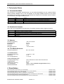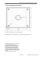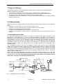
1
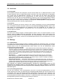
SICLOCK® DCFRS Industrieversion mit TTY-Interface 2XV9450-1AR21 Betriebsanleitung • User Manual D Deutsch Version 1.0 Stand: Oktober 2005 GB English Bestell.Nr. 2XV9450-1AR48 Betriebsanleitung SICLOCK DCFRS Industrieversion Verantwortlicher Vertrieb: Siemens AG, I&S EDM, Erlangen Ansprechpartner: örtliche Siemens-Niederlassung Bestellungen: örtliche Siemens-Niederlassung Herausgegeben von: Siemens AG I&S EDM Frauenauracher Straße 98 D-91056 Erlangen SICLOCK-Hotline: Tel.: ++49 (9131) 7-2 88 66 Fax: ++49 (9131) 18-8 06 04 Technische Änderungen vorbehalten E-mail: [email protected] WWW: http://www.siemens.de/siclock Siemens AG 2000, 2001, 2005 2 Version 1.0 Bestellnummer 2XV9450-1AR48 Betriebsanleitung SICLOCK DCFRS Industrieversion Inhaltsverzeichnis Abbildungsverzeichnis............................................................................................................................. 3 Tabellenverzeichnis ................................................................................................................................. 3 1 Lieferumfang........................................................................................................................................ 4 2 Inbetriebnahme.................................................................................................................................... 4 2.1 Funktionsbeschreibung................................................................................................................. 4 2.2 Anschluss...................................................................................................................................... 5 2.2.1 Zielsystem ............................................................................................................................... 5 2.2.2 Antenne ................................................................................................................................... 5 2.2.3 Kabelschirm............................................................................................................................. 5 2.3 Montage ........................................................................................................................................ 5 2.3.1 Standortwahl .......................................................................................................................... 5 2.3.2 Ausrichtung zum Sender ........................................................................................................ 5 2.3.3 Zusammenbau der Montagehalterung ................................................................................... 6 3 Technische Daten................................................................................................................................ 7 3.1 Schnittstelle RS232....................................................................................................................... 7 3.2 Schnittstelle Antenne ..................................................................................................................... 7 3.3 Antenne.......................................................................................................................................... 7 3.4 TTY-RS232-Konverter ................................................................................................................... 7 3.4.1 RS232-Sender......................................................................................................................... 7 3.4.2 Linienstrom (TTY).................................................................................................................... 7 4 Bestelldaten ......................................................................................................................................... 7 5 Antennenfußgestell-Vermaßung........................................................................................................... 8 Abbildungsverzeichnis Abbildung 1: Installationsschema mit Verkabelung................................................................................. 4 Abbildung 2: Abgewinkelte Montage der Montagehalterung................................................................... 6 Abbildung 3: Gestreckte Montage der Montagehalterung....................................................................... 6 Abbildung 4: Abmessungen des Antennenfußgestells............................................................................ 8 Tabellenverzeichnis Tabelle 1: Schnittstellenbelegung RS 232. ............................................................................................. 7 Tabelle 2: Schnittstellenbelegung Antennenanschluss........................................................................... 7 Bestellnummer 2XV9450-1AR48 Version 1.0 3 Betriebsanleitung SICLOCK DCFRS Industrieversion 1 Lieferumfang Im Lieferumfang von SICLOCK DCFRS Industrieversion (Best.Nr. 2XV9450-1AR21) sind folgende Komponenten enthalten: • • • • SICLOCK DCF77-Antenne mit TTY-Interface (Best.Nr. 2XV9450-1AR16 oder E89700-B9204-A1) Montagehalterung mit 2 Verteilerdosen (1 Verteilerdose bei Lieferung zusammen mit SICLOCK TM). Betriebsanleitung für die DCFRS Industrieversion (Bestell Nr. 2XV9450-1AR48). TTY-RS232-Umsetzer mit Steckernetzteil (nicht bei Lieferung zusammen mit SICLOCK TM in den Komplettpaketen 2XV9450-1AR26 und 27). 2 Inbetriebnahme Die Inbetriebnahme einer Zeitsynchronisation mit der DCFRS Industrieversion erfolgt in folgenden Teilschritten: • • • • • Zusammenbau der Montagehalterung entsprechend den räumlichen Gegebenheiten. Anschluß des TTY-RS232-Konverters an die RS232-Schnittstelle des Zielsystems. Montage der Verteilerdosen und des Steckernetzteils. Verbinden der beiden Verteilerdosen durch ein bauseits zu verlegendes Kabel. Installation des entsprechenden Empfangsdienstes auf dem Zielsystem (nicht im Lieferumfang enthalten). 2.1 Funktionsbeschreibung Die SICLOCK DCFRS-Antenne dient zum Empfang des DCF77-Zeitzeichensenders, welcher die offizielle Zeit der Bundesrepublik Deutschland sendet. Der Sender in Mainflingen bei Frankfurt überträgt jede Minute das aktuelle Datum und die aktuelle Zeit auf der Langwellenfrequenz 77,5 KHz. Durch die niedrige Frequenz stellen Gebäude und Landschaften für das Zeitsignal im wesentlichen keine Hindernisse dar, solange es nicht durch Metall abgeschirmt wird. Durch die Sendeleistung von 27 kW kann bei ungestörter Umgebung das Zeitsignal in Mitteleuropa empfangen werden. In dem Antennengehäuse sind die Antenne und die gesamte Empfangselektronik integriert. Der TTY-RS232-Umsetzer wird über ein Steckernetzteil oder eine andere 24V Gleich- oder Wechselspannungsquelle gespeist und liefert den Versorgungsstrom für die SICLOCK DCFRSAntenne. Er wandelt die Stromimpulse der Antenne (TTY) in Spannungssignale für eine RS232Schnittstelle um. Die Versorgung des RS232-Senders erfolgt durch Steuerleitungen der RS232Schnittstelle. Durch den Umsetzer wird der Antennenkreis von der RS232-Schnittstelle mit einer Isolationsspannung von 500V galvanisch getrennt. Abbildung 1 zeigt den Aufbau der Empfangsanlage. Bei den Gesamtpaketen SICLOCK TM mit DCF (2XV9450-1AR26 und 27) wird das von der antennenseitigen Verteilerdose kommende Kabel direkt mit dem Eingang E1 (Klemmleiste X2/4 und 6 bei SICLOCK TM) verbunden und der Schirm auf der Potentialausgleichsschiene des Schrankes aufgelegt. Das andere Ende der Leitung an der antennenseitigen Verteilerdose darf in diesem nicht geerdet sein! 500V max. Potentialtrennung RS232-Schnittstelle Zielsystem Antennenkreis RS232Sender V+ V- V- Verteilerdosen gelb Kabelgrün schirm braun weiß TTY-RS232-Umsetzer RS232Empfänger V+ max. 1000m 20mA Kabelschirm Erde DCF77-Antenne mit Montagehalterung Abbildung 1: Installationsschema mit Verkabelung. 4 Version 1.0 Bestellnummer 2XV9450-1AR48 Betriebsanleitung SICLOCK DCFRS Industrieversion 2.2 Anschluss 2.2.1 Zielsystem Die Schnittstelle zwischen dem Zielsystem und der Antenne bildet der TTY-RS232-Umsetzer. Er wird mit dem Zielsystem über eine RS232-Schnittstelle verbunden. Das andere Kabelende ist aufgesplittet, die 4 Adern sind mit Aderendhülsen versehen. An die weiße und die braune Ader wird das mitgelieferte Steckernetzteil (14V AC) angeschlossen. Es kann aber auch eine Gleichspannung zwischen 15V und 30V oder eine Wechselspannung zwischen 10V und 20V angeschlossen werden. Da im Konverter ein Gleichrichter integriert ist, muß auf die Polung nicht geachtet werden. An die gelbe und grüne Leitung wird das bauseits zu verlegende Verbindungskabel (2 adrig geschirmt, Schleifenwiderstand kleiner 150 Ohm) angeschlossen. 2.2.2 Antenne Die beiden Anschlüsse der Antenne werden in der zweiten Verteilerdose mit dem Verbindungskabel zum TTY-RS232-Umsetzer verbunden. Dabei muß ebenfalls keine Polung beachtet werden. Nach dem Starten des Empfangsdienstes am Zielsystem muß die Leuchtdiode an der Antenne im Sekundentakt zu blinken beginnen. Anschließend kann mit der Montage und dem Ausrichten der Antenne begonnen werden. 2.2.3 Kabelschirm Der Schirm des bauseits verlegten Verbindungskabels zwischen dem TTY-RS232-Umsetzer und der Antenne sollte an einem Kabelende niederohmig mit Erde verbunden werden. Dafür eignen sich besonders Erdungsschienen von Schaltschränken oder Wasserleitungen. Auf keinen Fall darf eine beidseitige Erdung erfolgen, da dies hohe Potenzialausgleichsströme über den Kabelschirm zur Folge haben kann. 2.3 Montage 2.3.1 Standortwahl Am Anfang der Antennenmontage sollte die sorgfältige Auswahl des Standortes stehen. Er bestimmt entscheidend die Empfangsqualität und damit die Verfügbarkeit des DCF77-Empfangssignals. Er kann maximal 1000 m vom zu synchronisierenden Gerät entfernt sein. Bei der Standortwahl sollten folgende Kriterien optimiert werden: • • • Abstand zu elektrischen Geräten: Jedes elektrische Gerät sendet elektromagnetische Stahlung aus, welche den Empfang verschlechtert. Deshalb sollte die Antenne möglichst weit von elektrischen Geräten entfernt aufgestellt werden. Besonders hohen Störpegel weisen Monitore, PCs, Laserdrucker, Motorantriebe und Neonröhren auf, weshalb zu diesen Geräten ein maximaler Abstand einzuhalten ist. Es sollte auch beachtet werden, daß das Antennenkabel nicht parallel zu Leistungskabeln (z. B. Versorgungskabel für Motoren) verlegt wird. Abschirmung: Metallische Gegenstände schirmen das Empfangssignal ab und verschlechtern dadurch die Empfangsqualität. Deshalb sollte zu metallischen Flächen und Gegenständen ein möglichst großer Abstand eingehalten werden. Dabei sollte auch bedacht werden, daß die im Stahlbeton enthaltene Stahlarmierung unter Umständen das Feld abschwächt.. Ausrichtung zum Sender: Der Sender, welcher das DCF77-Zeitsignal sendet, steht in der Nähe von Frankfurt. Der in einem modernen Gebäude verbaute Stahl schwächt das Empfangssignal ab. Im Hinblick auf optimale Empfangsbedingungen sollte der Empfangsort am besten auf der Frankfurt zugewandten Seite gewählt werden. Außerdem sollte die Antenne in möglichst großer Höhe montiert werden. Zum Auffinden des optimalen Empfangsstandortes innerhalb der Industrieanlage bieten wir eine Vermessung der gesamten Anlage an. Auf diese Weise wird in der Regel mindestens ein Standort gefunden, der einen problemlosen und störungsfreien DCF77-Empfang ermöglicht. Rufen Sie uns an, wir helfen Ihnen gerne. 2.3.2 Ausrichtung zum Sender Wie bei einer Rundfunk- oder Fernsehantenne muß auch die DCF77-Empfangsantenne auf den Sender ausgerichtet werden. Zur Beurteilung der Empfangsqualität befindet sich auf der Antenne eine Leuchtdiode, welche bei störungsfreiem Empfang jede Sekunde kurz ausgeht. Zum Ausrichten muß die Antenne wie in Kapitel 2.2. beschrieben mit dem Zielsystem verbunden werden. Außerdem muß der Empfangsdienst gestartet werden, damit der TTY-RS232-Umsetzer mit Energie versorgt wird. Die Montagehalterung erlaubt eine beliebige Ausrichtung der Antenne. Bestellnummer 2XV9450-1AR48 Version 1.0 5 Betriebsanleitung SICLOCK DCFRS Industrieversion 2.3.3 Zusammenbau der Montagehalterung Die Abbildungen 2 und 3 zeigen die zwei Zusammenbaumöglichkeiten für die Montagehalterung. Dabei ist zu beachten, daß das Anschlusskabel der Antenne (1) durch den Montagewürfel (3) und das Montagegestell (4) geführt und durch die Nut an der Bodenplatte nach außen verlegt wird. Nach dem Überprüfen des Empfangsstandortes (Empfangsgerät synchronisiert auf die Uhrzeit auf) wird die Montagehalterung durch die Befestigungslöcher der Bodenplatte angeschraubt. Abbildung 2: Abgewinkelte Montage der Montagehalterung. Abbildung 3: Gestreckte Montage der Montagehalterung. Nach der Montage und der Ausrichtung der Antenne wird die Verschlusskappe (2) in die verbleibende Würfelöffnung gedrückt. Anschließend müssen die 6 Madenschrauben im Montagewürfel (4) mit dem mitgelieferten Inbusschlüssel (5) angezogen werden. 6 Version 1.0 Bestellnummer 2XV9450-1AR48 Betriebsanleitung SICLOCK DCFRS Industrieversion 3 Technische Daten 3.1 Schnittstelle RS232 Zum Anschluss von DCFRS Industrieversion an die RS232-Schnittstelle wird ein 9-poliger DSUBStecker benötigt. Befindet sich an der Schnittstelle ein 25-poliger DSUB-Anschluss für die serielle Schnittstelle, so muß dieser mit Hilfe eines handelsüblichen Adapters auf 9 Kontakte reduziert werden. Die Schnittstelle weist folgende Belegung auf: Pin 2 4 5 7 Name RxD DTR GND RTS Funktion Demoduliertes DCF77-Empfangssignal, 1 Impuls pro Sekunde negative Versorgungsspannung, nur bei aktiviertem Empfangsdienst Signalmasse positive Versorgungsspannung, nur bei aktiviertem Empfangsdienst Tabelle 1: Schnittstellenbelegung RS 232. 3.2 Schnittstelle Antenne Die 4 Adern am aufgesplitteten Anschluss des TTY-RS232-Umsetzers haben folgende Funktion: Farbe gelb grün braun weiß grau Funktion Verbindung zur Antenne (negatives Potential) Verbindung zur Antenne (positives Potential) Versorgungsspannung Antennenkreis TTY-RS232-Umsetzer Anschluß 1 Versorgungsspannung Antennenkreis TTY-RS232-Umsetzer Anschluß 2 Kabelschirm Tabelle 2: Schnittstellenbelegung Antennenanschluss. 3.3 Antenne Abmessung (BxHxT): Empfindlichkeit: Bandbreite: Schutzart: Betriebstemperatur: 185 x 80 x 65 mm 0,3 µV 400 Hz IP 65 -10°C bis +50°C 3.4 TTY-RS232-Konverter Abmessung (BxHxT): 60 x 30 x 40 mm 3.4.1 RS232-Sender Versorgungsspannung: Ruhestrom: max. Ausgangsstrom: +/- 8V bis +/- 15V 4 mA +/- 25 mA 3.4.2 Linienstrom (TTY) Versorgungsspannung: Ausgangsstrom: galvanische Trennung: max. Kabellänge: Schleifenwiderstand: 10V AC bis 20V AC oder 15V DC bis 30V DC 20 mA 500V 1000m, 2-adrig verdrillte und geschirmte Leitung, kleiner 150 Ohm. 4 Bestelldaten SICLOCK DCFRS Industrieversion (TTY-Schnittstelle) ......................................................................................2XV9450-1AR21 SICLOCK Betriebsanleitung für DCFRS-Industrieversion (TTY-Schnittstelle).....................................................2XV9450-1AR48 SICLOCK DCFRS Antenne mit TTY-Schnittstelle...............................................................................................2XV9450-1AR16 SICLOCK Empfangsdienst für DCF77 für SIMATIC S7 AS300/AS400 ...............................................................2XV9450-1AR32 SICLOCK Installationsanleitung für Empfangsdienst für DCF77 für SIMATIC S7 AS300/AS400 ........................2XV9450-1AR33 SICLOCK Empfangsdienst für Windows 95/98/2000/NT ....................................................................................2XV9450-1AR28 SICLOCK Installationsanleitung für Empfangsdienst für Windows 95/98/2000/NT..............................................2XV9450-1AR20 Bestellnummer 2XV9450-1AR48 Version 1.0 7 Betriebsanleitung SICLOCK DCFRS Industrieversion 5 Antennenfußgestell-Vermaßung Abbildung 4: Abmessungen des Antennenfußgestells. Die Befestigung des Antennenfußgestells erfolgt mit 4 Senkkopfschrauben 5 mm. Die Warenzeichen SICLOCK, DCFRS der SIEMENS AG sind durch Eintrag gesetzlich geschützt. Technische Änderungen des Produkts vorbehalten. Diese Beschreibung gilt nicht als Zusicherung von Eigenschaften. Technische Daten und Abbildungen sind unverbindlich für die Lieferung. Weitergabe sowie Vervielfältigung dieser Unterlage, Verwertung und Mitteilung ihres Inhalts ist nicht gestattet, soweit nicht ausdrücklich zugestanden. Zuwiderhandlungen verpflichten zu Schadensersatz. Alle Rechte vorbehalten, insbesondere für den Fall der Patenterteilung oder GMEintragung. Siemens AG 2000, 2001, 2005 8 Version 1.0 Bestellnummer 2XV9450-1AR48 SICLOCK® DCFRS Industrial Version with TTY Interface 2XV9450-1AR21 User Manual Version 1.0 Revision: October 2005 Order No. 2XV9450-1AR48 User Manual SICLOCK DCFRS Industrial Version Responsible Distributor: Siemens AG, I&S EDM, Erlangen Contact Person: local SIEMENS branch Orders: local SIEMENS branch Published by: Siemens AG I&S EDM Frauenauracher Straße 98 D-91056 Erlangen SICLOCK-Hotline: Phone: ++49 (9131) 7-2 88 66 Fax: ++49 (9131) 18-8 06 04 Technical changes reserved E-mail: [email protected] WWW: http://www.siemens.com/siclock Siemens AG 2000, 2001, 2005 2 Version 1.0 Order No. 2XV9450-1AR48 User Manual SICLOCK DCFRS Industrial Version Contents 1 Scope of Delivery.................................................................................................................................. 4 2 Commissioning ..................................................................................................................................... 4 2.1 Description of Function .................................................................................................................. 4 2.2.1 Target System ......................................................................................................................... 5 2.2.2 Antenna ................................................................................................................................... 5 2.2.3 Cable Shield ............................................................................................................................ 5 2.3 Mounting ....................................................................................................................................... 5 2.3.1 Choice of Location................................................................................................................... 5 2.3.2 Alignment to the Transmitter ................................................................................................... 5 2.3.3 Assembly of the Antenna Frame............................................................................................. 6 3 Technical Data...................................................................................................................................... 7 3.1 Interface RS232 ............................................................................................................................. 7 3.2 Interface Antenna........................................................................................................................... 7 3.3 Antenna.......................................................................................................................................... 7 3.4 TTY-RS232-Converter ................................................................................................................... 7 3.4.1 RS232-Sender......................................................................................................................... 7 3.4.2 Line current (TTY) ................................................................................................................... 7 4 Ordering data........................................................................................................................................ 7 5 Antenna Foot Stand Dimensioning....................................................................................................... 8 Index of Figures Fig. 1: Installation schema with cabling................................................................................................... 4 Fig. 2: Angled mounting of the fixing bracket .......................................................................................... 6 Fig. 3: Extended mounting of the fixing bracket. ..................................................................................... 6 Fig. 4: Dimensions of the antenna foot stand.......................................................................................... 8 Index of Tables Table 1: Interface assignment RS 232. ................................................................................................... 7 Table 2: Interface assignment antenna connection................................................................................. 7 Order No. 2XV9450-1AR48 Version 1.0 3 User Manual SICLOCK DCFRS Industrial Version 1 Scope of Delivery In the scope of delivery of SICLOCK DCFRS industrial version (Order No. 2XV9450-1AR21) the following components are included: • • • • SICLOCK DCF77 antenna with TTY-Interface (order No. 2XV9450-1AR16 or E89700-B9204-A1) Antenna frame with 2 distribution boxes (1 distribution box included with the delivery of SICLOCK TM). Operating manual for die DCFRS industrial version (order No. 2XV9450-1AR48). TTY-RS232 converter with AC adapter (not for delivery together with SICLOCK TM in the complete packages 2XV9450-1AR26 and 27). 2 Commissioning Commissioning a time synchronization with the DCFRS industrial version is carried out in the following steps: • • • • • Assembly of the antenna frame in accordance with the situation on site. Connection of the TTY-RS232 converter to the RS232 interface of the target system. Installation of the distribution boxes and AC adapter. Connection of the two distribution boxes by means of a cable laid on site. Installation of the appropriate reception service into the target system (not included under the scope of delivery). 2.1 Description of Function The SICLOCK DCFRS antenna serves the reception of the DCF77 time signal transmitter for the transmission of the official time of day in the Federal Republic of Germany. The transmitter in Mainflingen near Frankfurt transmits at minute intervals the current date and absolute time on the long wave frequency 77.5 kHz. The low frequency means that buildings and landscape properties are essentially not a hindrance for the time signal, insofar as it is not shielded by metal. Through the transmission output of 27 kW, the time signal can be received in an interference free environment throughout Central Europe. The antenna and all the reception electronics are integrated in the antenna housing. The TTY-RS232 converter is fed by an AC adapter or another 24V source of direct or alternating voltage and provides the supply current for the SICLOCK DCFRS antenna. It changes the current pulses of the antenna (TTY) into voltage signals for a RS232 interface. Power supply to the RS232 transmitter is via control leads of the RS232 interface. The converter brings about galvanic separation of the antenna circuit of the RS232 interface with an isolation voltage of 500V. Figure 1 shows the structure of the reception unit. When using the complete packages SICLOCK TM with DCF (2XV9450-1AR26 or 27), the cable coming from the antenna distribution box is directly connected to the input E1 (terminal bar X2/4 and 6 at SICLOCK TM) and the cable shield must be earthed on the earth bar in the cabinet instead of the earth connection at the antenna distribution box. 500V max. isolation RS232-interface target system max. 1000m antenna circuit TTY-RS232-converter RS232receiver V+ RS232transmitter V+ V- V- distribution box yellow cable green shield brown white 20mA cable shield Earth DCF77-antenna with footstand Fig. 1: Installation schema with cabling. 4 Version 1.0 Order No. 2XV9450-1AR48 User Manual SICLOCK DCFRS Industrial Version 2.2 Connection 2.2.1 Target System The interface between the target system and the antenna is provided by the TTY-RS232 converter. It is connected to the target system via a RS232 interface. The other end of the cable is spit, the 4 wires are provided with wire end ferrules. The AC adapter (output 14V AC) supplied is connected to the white and brown wires. A direct current between 15V and 30V or an alternating current between 10V and 20V can also be connected. There is a rectifier integrated in the converter and therefore there is no need to take the polarity into account. The cable to be laid on site is connected to the yellow and green lead (2-wire shielded, loop resistance less than 150 Ohm). 2.2.2 Antenna The two antenna connections are connected in the second distribution box with the connecting cable to the TTY-RS232 converter. Here, too, there is no need to take polarity into account. After starting the reception service on the target system, the LED on the antenna must begin to flash in second tact. Then the mounting of the antenna and its alignment can begin. 2.2.3 Cable Shield The shield of the connection cable laid on site between the TTY-RS232 converter and the antenna should be connected to one cable end low-resistance with the earth. Specially suitable for this are earth bars from switch cabinet or water pipes. Under no circumstances should there be an earth on both sides, as this can result in high potential equalizing currents over the cable shield. 2.3 Mounting 2.3.1 Choice of Location Before beginning to mount the antenna the location for this should be selected with care. This is significant for the quality of the reception and therefore of the availability of the DCF77 reception signal. It can be at a maximum of 1000 m away from the unit to be synchronized. In selecting the location, the following criteria should be optimized: • Distance from electric equipment: Every electrical appliance sends out electro-magnetic radiation which impairs reception. The antenna should therefore be set up as far away as possible from electrical appliances. A particularly high disturbance level is caused by monitors, PCs, laser printers, motor drives and neon tubes, and maximum distance should therefore be maintained from such equipment. Care should also be taken that the antenna cable is not laid parallel to the output cables (e.g. supply cable for motors). • Shielding: Metal objects shield the reception signal and thus impair quality of reception. As great a distance as possible should therefore be maintained to metal surfaces and objects. It should also be noted that under certain circumstances, the steel reinforcement in reinforced concrete weakens the field. • Alignment to the transmitter: The transmitter which sends out the DCF77 time signal is located near to Frankfurt. The steel which is incorporated in modern buildings weakens the reception signal. In respect of optimum conditions for reception, the place of reception is preferably chosen on the side facing Frankfurt. In addition, the antenna should be mounted as high as possible. In order to find the optimum location for reception within the industrial premises we offer a survey of the whole plant area. In this way as a rule, at least one location can be found which facilitates problem-free and interference-free DCF77 reception. Just give us a call and we shall be pleased to help you. 2.3.2 Alignment to the Transmitter As for a radio or television antenna, the DCF77 reception antenna must also be aligned to the transmitter. To assess the quality of reception there is a red LED on the antenna, which lights up briefly every second during interference-free reception. For alignment, the antenna must be connected to the target system as described in chapter 2.2. In addition, the reception service must be started, so that the TTY-RS232 converter is supplied with energy. The antenna frame permits any alignment of the antenna as required. Order No. 2XV9450-1AR48 Version 1.0 5 User Manual SICLOCK DCFRS Industrial Version 2.3.3 Assembly of the Antenna Frame The figures 2 and 3 show the two possible ways of assembling the antenna frame. It should be noted that the connection cable of the antenna (1) is led through the mounting cube (3) and the foot stand (4) and laid outwards through the groove on the floor plate. Once the location has been tested for reception (reception unit synchronized to the time of day), the fixing bracket is screwed into place through the fixing holes of the floor plate. After mounting and aligning the antenna, the locking cap (2) is pressed into the opening remaining in the cube. The 6 grub screws in the mounting cube (4) must then be screwed tight using the Allen type wrench (5) supplied. Fig. 2: Angled mounting of the antenna frame. Fig. 3: Extended mounting of the antenna frame. 6 Version 1.0 Order No. 2XV9450-1AR48 User Manual SICLOCK DCFRS Industrial Version 3 Technical Data 3.1 Interface RS232 For connecting the DCFRS industrial version to the RS232 interface a 9-pole DSUB plug is required. If on the interface there is a 25-pole DSUB connector for serial interface, then this must be reduced to 9 contacts with the aid of a customary adapter. The interface has the following assignment: Pin 2 4 5 7 Name RxD DTR GND RTS Function Demodulated DCF77 reception signal, 1 pulse per second negative supply voltage, only when reception service is activated Signal ground positive supply voltage, only when reception service is activated Table 1: Interface assignment RS 232. 3.2 Interface Antenna The 4 wires on the split connection of the TTY-RS232 converter have the following function: Color yellow green brown white grey Function Connecting to the antenna (negative potential) Connecting to the antenna (positive potential) Supply voltage antenna circuit TTY-RS232 converter connection 1 Supply voltage antenna circuit TTY-RS232 converter connection 2 Cable shield Table 2: Interface assignment antenna connection. 3.3 Antenna Dimensions (WxHxD): Sensitivity: Band width: Type of Protection: Operating temperature: 185 x 80 x 65 mm 0,3 µV 400 Hz IP 65 -10°C to +50°C 3.4 TTY-RS232-Converter Dimensions (WxHxD): 60 x 30 x 40 mm 3.4.1 RS232-Sender Supply voltage: Zero signal current: max. Output current: +/- 8V to +/- 15V 4 mA +/- 25 mA 3.4.2 Line current (TTY) Supply voltage: Output current: Isolation voltage: max. cable length: Loop resistance: 10V AC to 20V AC or 15V DC to 30V DC 20 mA 500V 1000m, 2-wire drilled and shielded lead, less than 150 Ohm. 4 Ordering data SICLOCK DCFRS industrial version (TTY interface) ..........................................................................................2XV9450-1AR21 SICLOCK Operating manual for DCFRS industrial version (TTY interface) ........................................................2XV9450-1AR48 SICLOCK DCFRS antenna with TTY interface ...................................................................................................2XV9450-1AR16 SICLOCK Reception service for DCF77 for SIMATIC S7 AS300/AS400 ............................................................2XV9450-1AR32 SICLOCK Installation manual for reception service for DCF77 for SIMATIC S7 AS300/AS400 ..........................2XV9450-1AR33 SICLOCK Reception service for Windows 95/98/2000/NT..................................................................................2XV9450-1AR28 SICLOCK Installation manual for reception service for Windows 95/98/2000/NT................................................2XV9450-1AR20 Order No. 2XV9450-1AR48 Version 1.0 7 User Manual SICLOCK DCFRS Industrial Version 5 Antenna Foot Stand Dimensioning Fig. 4: Dimensions of the antenna foot stand. The antenna foot stand is fixed in place by means of 4 countersunk screws 5 mm. SICLOCK, DCFRS, GPSDEC, are registered trademarks of SIEMENS AG. Technical data subject to change. We have checked the contents of this manual for agreement with the hardware described. Since deviations cannot be entirely precluded, we cannot guarentee full agreement. The reproduction, transmission or use of this document or its contents is not permitted without express written authority. Offenders will be liable for damages. All rights, including rights created by patent grant of a utility or design are reserved. Siemens AG 2000, 2001, 2005 8 Version 1.0 Order No. 2XV9450-1AR48