1
E-nl 918
H>l1I\I
OlOnlS30 13NNOl133HIO
3NOHdOH31""
3NOHdOH31""
OlOnlSl'vNO1133H10
NO~OH}II
""lH3IH-010nlS
IOld""3,O300""
301n9S,H3Sn
9Nnl131N'VS9NnN31038
H:lSI:lHI\II\I:lS [Zj
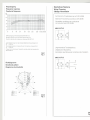
Frequenzgang
Frequency response
Courbe de frequence
Beschaltung / Speisung
Wiring / Powering
Cäblage/ Alimentation
dB
50
Symmetrische
40
--
-
30
20
nach DIN 45595
to DIN 45595
Alimentation symetrlque par conducteurs
de modulation selon DIN 45595
+
10 -
Tonaderspeisung
Balanced A-ß powering according
-,
MKH 816 TU-3
0
20
50
100
200
500
1000
2000
5000
10000 20000Hz!
--ru_nni
i-
i
Sollfrequenzgang mit Toleranzsehema MKH 816 TU-3
Standard response eurve wifh foleranees MKH 816 TU"3
Courbe de reponse de eonsigne avee toleranee MKH 816TU-3
I
I
~
'
I
iQJ
23
L_uLu
I
I
I
1
:
-
J
I
I
1
I
Jedem Mikrofon legen wir das Origlnal-Meßprotokoll bei, gemessen von
50
20000 Hz,
The ollglnal diagram ISIneluded wlth eaeh microphone, measured from
50
20000 Hz.
Unsymmetrische
Chaque miere est livre avee I'origlnal du proees-verbal des mesures entre
50 et 20000 Hz.
Abb.1
Fig.1
Tonaderspeisung
Unbalanced
A-B powering
Aliment~tion
asymetrique
par conducteurs
de modulation
MKH 816 TU-3
:-I
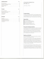
Richtdiagramm
Directional pattern
Diagramme de directivite
I
I
I
I
-rn__n:
I
2
@
Lu_Iuu
3
---J
I
I
I
I
I
Qj
od"/m/cc
I
60"
\
)900
J'
- /~
/j
./
---
/i
!
.
'
/
/;
/
1200
<?
.
1500
2000
4000
8000
16000
Hz Hz -Hz -.Hz --
Abb.2
Fig.2
Abb.
Fig.3
Inhaltsverzeichnis
Seite
3
3
3
5
6
Kurzbeschreibung. . . . . . . . . . . . . . . . . . . . . . . . . . . . . . .
Prinzip der Hochfrequenzschaltung
Speisung und Anschluß
Technische Daten. .
Zubehör. . .
Contents
Page
General descrlption ..
..
Principle of high frequency circuit. . .
Powering and connection . . . . . . . .
Technical data . .
Accessories. .
8
8
8
. 10
. 11
.. .. .. ..
Sommaire
Page
Descriptlon . ..
..
Montage haute frequence . .
Alimentation et branchement
. .
Caracteristiques techniques . . .
Accessoires.. . ..
.......
...
.
...
..
.
.
.
.
.
13
13
13
15
16
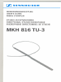
STUDIO-RICHTMIKROFON
MKH 816 TU-3
Lieferumfang:
1 Mikrofon
Kurzbeschreibung
Das Studio-Richtmikrofon
MKH 816 T ist ein Kondensator-Mikrofon
in Hochfrequenzschaltung.
Oie zum Betrieb des Mikrofones notwendige Gleichspannung
von 12 Volt wird über die beiden Tonadern
des Anschlußkabels zugeführt (Tonaderspeisung nach DIN 45595).
Eigenschaften:
. Hoher Bündelungsgrad
. Sehr gute Rückkopplungsdämpfung
. Niedriger Aqulvalentschalldruckpegel
. Robust und extrem klimafest
. Hoher Feldleerlauf-Übertragungsfaktor
. Ganzmetallgehäuse, mattschwarz eloxiert
Prinzip der Hochfrequenzschaltung
Oie Kapsel eines Kondensator-Mikrofons
in Hochfrequenzschaltung
stellt im Gegensatz zu der In Niederfrequenzschaltung
eine niederohmige Impedanz dar. An der Kapsel liegt anstelle der sonst nötigen hoheri Polarisationsspannung
lediglich eine Hochfrequenzspannung von etwa 10 V, die durch einen rauscharmen Oszillator
(8 MHz) erzeugt wird. Oie niedrige Kapselimpedanz führt zu einer
hohen Betriebssicherheit der Mikrofone.
Speisung und Anschluß
Von Sennheiser electronic wurde die Tonaderspeisung
die dann in DIN 45595 genormt wurde.
eingeführt,
Wie bei dynamischen Mikrofonen sind bel dieser Speisungstechnik
zum Anschluß nur zwei Adern im Mikrofonkabel erforderlich. Der
Speisestrom nimmt denselben Weg wie die Tonfrequenzspannung,
sodaß die Schaltung im Mikrofon nicht galvanisch mit Masse verbunden ist. Durch diese "erdfreie Technik" ergeben sich die höchstmöglichen Werte für die Störfestigkeit. Geeignete Speisegeräte sind
im Abschnitt "Zubehör" beschrieben.
Beim Anschluß der Sennheiser-Kondensator-Mlkrofone
wird eben-
so wie bei dynamischen Mikrofonen vom Prinzip der Spannungsanpassung Gebrauch gemacht. Der Vorteil IStdabei, daß weder der
Impedanzverlauf des Mikrofonausganges
noch der des Verstärkereinganges einen nennenswerten Einfluß auf den Gesamt-Frequenz-
3
gang haben. Die Quellimpedanz der Sennheiser-KondensatorMikrofone mit Tonaderspeisung
ist so klein (etwa 8 Q bel 1000 Hz),
daß von der Eingangsimpedanz
des Verstärkers nur verlangt wird,
daß sie mindestens 400 Q beträgt. Das Ist meist der Fall. Sollte
dennoch ein Eingang mit geringerer Impedanz vorliegen, so muß
man mit einem geeigneten Vorwiderstand dafür sorgen, daß das
Mikrofon mindestens 400 Q »sieht«. Die dabei auftretende
Spannungsteilung
muß natürlich berücksichtigt werden. Dieselbe
Methode wird angewandt, wenn eine höhere AusgangsImpedanz
des Mikrofons verlangt wird. Auch in diesem Fall kann man sich
durch Vorschalten eines entsprechenden Widerstandes helfen.
Die Sennheiser-Kondensator-Mikrofone
geben relativ hohe
Spannungen ab, bel maximalen Schalldrücken fast 1 V. Das hat den
Vorteil, daß auch bei großen Kabellängen eingekoppelte Störspannungen keine Bedeutung erlangen. Weiterhin geht auch das
Eigenrauschen des Mikrofonverstärkers
kaum noch in das Gesamtrauschen ein. Die Mikrofone sind außerdem mit reichlich bemessenen Hochfrequenzsiebgliedern
ausgestattet, die dafür sorgen, daß
keine Hochfrequenzspannungen
auf die Mikrofonleitungen gelangen und die gleichzeitig die Mikrofone gegen Hochfrequenzstörungen von außen schützen. Es ist deshalb auch unter schwierigen Verhältnissen nicht notwendig, besondere Maßnahmen, wie
Doppelabschirmung
der Leitungen und hochfrequenzdichte
Stekker, vorzusehen. Sennheiser-Kondensator-Mlkrofone
sind nach DIN
gepolt, d. h. bei Auftreten eines Druckimpulses von vorn auf die
Kapsel tritt an Stift 2 bei XLR-Steckverbindern
eine positive
Spannung gegenüber Stift 3 auf.
Übertragungsbereich. .
Akustische Arbeitsweise
Richtcharakteristik . . . . . . .
FeIdleerlauf-Übertrag ungsfaktor
bei 1000 Hz
......
Elektrische Impedanz bei 1000 Hz .
Nennabschlußimpedanz.
.
Äq uivalentschalld ruc kpeg el
nach CCIR 468-1
Kurve A
.
Aussfeuerungsg renze
Speisespannung
Speisesfrom . . .
Temperaturbereich.
Stecker
Beschaltung
Abmessungen in mm
Gewicht
40
.20000 Hz
Interferenzempfänger
Keule
40 mV/Pa i: 1dB
ca. 8 Q, symmefrisch, erdfrei
"" 400 Q (200 Q bis 10 Pa)
ca. 26 dB
ca. 15 dB
15 Pa ("'118 dB)
12 Vi: 2 V
ca. 6 mA
-10°C bis + 70°C
3pol. XLR-3-Stecker,
System Cannon
1: Gehäuse, 2: NF, 3: NF
nach IEC-Normvorschlag
(Publication 268-14 B)
19 cj;,555 lang
375 9
Änderungen, vor allem zum technischen Fortschritt, vorbehalfen.
Anschluß an symmetrische Mikrofoneingänge
In diesem Fall verbindet man das Mikrofon mit dem Netzgerät
MZN 16 TU oder einen Batteriespeiseadapter
MZA 14 TU und
deren Ausgang wiederum mit dem Verstärkereingang.
Anschluß an unsymmetrische Mikrofoneingänge
Stehen nur unsymmetrische Eingänge zur Verfügung, ist hinter
dem Speisegerät der Kontakt 3 zu erden (bei Verwendung des
MZN 16 TU nur nach der Modifikation des Speisegerätes möglich).
Außerhalb der Studiotechnik ist das in den meisten Fällen unkritlpch,
da der hohe Ausgangspege11m Zusammenhang
mit der niedrigen
Quellimpedanz des Kondensatormikrofons
für einen genügend
großen Störabstand sorgt. Es muß aber darauf geachtet werden,
daß durch den Aufbau auf Stativen usw. keine mehrfachen
Erdungen entstehen.
Anschluß an Mikrofoneingänge
mit hoher Eingangsempfindlichkeit
Wenn das vorhandene Gerät eine zu hohe Eingangsempfindlichkeit
besitzt, z. B. wenn er für niederohmige dynamische Mikrofone
vorgesehen ist, kann es notwendig werden, den Pegel der Kondensatormikrofone mit Hilfe eines Spannungsteilers
herunterzusetzen.
Dieser soll In der Mikrofonleitung am Verstärkereingang angeordnet
werden. Hierdurch wird In dem eigentlichen Mikrofonkreis der hohe
Pegel bewahrt, was sich günstig auf den Störabstand auswirkt.
Anschluß an Mischpulte und Tonaufzeichnungsgeräte
mit
Speisemöglichkeit
Wenn eine geeignete Spannung zur Verfügung steht, kann das
Kondensatormikrofon
daraus direkt gespeist werden. Die Spannung
soll hierzu 12 V::t 2 V betragen. Sie muß so stabilisiert und gesiebt
sein, daß die Fremdspannung kleiner als 5 f1.Vund die Geräuschspannung kleiner als 2 f1.V1St.Die Stromaufnahme beträgt etwa
6 mA, die nach Norm vorgeschriebenen
SpeisewIderstände
betragen dabei 2 x 180 Q. Das heißt, es fallen etwa 2 V an den Speisewiderständen ab (Abb. 3).
4
5
,
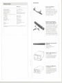
Zubehör
Federhalterung MZS 16
(Art.-Nr.2992)
Halterung mit gummigelagerten
Kunststoffklammern.
Sehr gute
Körperschalldämpfung.
Mit 3fs"Gewindebohrung
zur Befestigung an Mikrofonangeln,
Decken- oder Wandbefestigungen oder auf Stativen.
Windschutz-Kombination
MZW 816, MZS 16, MZP 816
(Art.-Nr.1930/2992/1932)
Die Kombination besteht aus
dem bruchsicheren und leichten
Windschutzkorb
MZW 816, der
Federhalterung MZS 16 und dem
Im Neigungswinkel
verstellbaren
Pistolengriff MZP 816.
Die Kombination ist vor allem für
den Reportageeinsatz Im Freien
geeignet und zeichnet sich durch
einfache Handhabung und gute
Körperschall-und Winddämpfung
aus.
,
tQ3
3Qi
L
XLR-3-11
~
XLR-3-12 C
C
r
Anschlußkabel KA 7 U
(Art.-Nr.1777)
Beidseitig mit XLR-Steckverbindern ausgerüstet.
Länge: 7,5 m.
--
,
Anschlußkabel KA 7 UN
(Art.-Nr.2157)
Geeignet für alle Senn heiserMikrofone mit XLR-Steckverbindern (System Cannon).
Geräteseitig 3pol., verschraubbarer Normstecker (z. B.
T 3260001). Länge: 7,5 m.
~
L
,01
XLR-3-11 C
T 3260 001
~
Weiteres Zubehör finden Sie im Sennheiser-Gesamtkatalog.
Nahbesprechungs-und
Windschutz MZW 815
(Art.-Nr. 0896)
Schaum netz-Windschutz
MKH 8161.
für
Speiseadapter MZA 14 TU
(Art.-Nr. 2959)
Zur netzunabhängigen
Spannungsversorgung
von
einern tonadergespeisten
Kondensatormikrofon
nach
DIN 45595.
Netzgerät MZN 16 TU
(Art.-Nr.1237)
Für den gleichzeitigen Betrieb
von zwei tonadergespeisten
Mikrofonen. Ausführung mit
XLR-Steckverbindem.
Abmessungen: 168x120x50 mm.
6
7
DIRECTIONALSTUDIO
MICROPHONEMKH816TU-3
Delivery: 1 microphone
General Description
The directional studio microphone MKH 816 T is a transistorized RF
condenser microphone. The DC voltage necessary lor operation IS
led through the conductors 01the connecting cable (A-B powering
according to the German standard DIN 45595).
Features:
. High directionality
. Low equivalent sound pressure level
. Rugged and extremely resistant to unlavourable climatic
conditions
. High sensitivity
. All metal housing with black linish
response. The source impedance 01the Senn heiser condenser
microphones with A-B powering is so low (approx. 8 Q at 1000 Hz)
that an amplilier input with an impedance 01at least 400 Q will be
suitable. This is usual in the majority 01 cases. However, il the Input
impedance is smaller than 400 Q, a reslstor 01 appropriate
value should be placed in se ries with the microphone so that it
"sees" aleast 400 Q. The voltage division caused by this series
resistor must 01 course be consldered. The same method can be
used when a highter output impedance 01the microphone is
demanded. In this case again aseries resistor can be used to
provide correct matching.
Senn heiser condenser microphones produce relatively large output
voltages; these can be up to 1 volt with maximum sound pressure
levels. This has the advantage that even with long cables induced
interference signals can be disregarded. Also the internat noise
produced by the microphone does not contribute to the total noise
level. The microphones are litted with high Irequency lilters, wh ich
ensure that no high Irequency signals Irom the microphone can
allect the external circuitry, and also that the microphone Itsell is
protected Irom high Irequency disturbance. It is, therelore, not
necessary, even under the most dillicult conditions, to take special
precautions such as double screening 01 the cables or the provision
01 high Irequency lilters.
Sennheiser condenser microphones are polarised according to
DIN standard, i. e. when apressure signal strikes the capsule Irom
the lront pin 2 01the XLR-connector goes positive with relerence
to pin 3.
Principle of high frequency
circuit
The capsule 01 an RF condenser microphone presents, contrary 10
low Irequency circuits, a low impedance output. Instead 01 the high
polarization voltage normally required, a high Irequency capsule
needs only a high Irequency voltage 01 about 10 volts, wh ich is produced bya built-in low noise oscillator (8 MHz). The low capsule
impedance leads to a high performance reliability 01the mlcrophones.
Connection to balanced microphone inputs
In this case the microphone is simply connected to the input 01 an
amplilier via a battery adapter MZA 16 TU or the power supply unit
MZN 14 TU.
Powering and connection
Sennheiser electronic introduced A-B powering, which was then
standardized in DIN 45595. As with dynamic microphones, only
two wires are required to connect the microphone when this
powering system is being used. The operating current is led along
the same wires as the audio Irequency signal, so that the circuitry in
the microphone does not have to be connected to earth. Because
01this earth Iree technique the highest possible values 01 immunity
lrom noise or disturbance are achieved. For suitable powering units
see "Accessories".
Apart Irom cases where the microphone is being used lor prolesslonal studio purposes, thls IS not critical, as the large output voltage
01the mlcrophone combined with its low output impedance provi des a large signal to noise ratio. Care should be taken, however,
that no multiple ground circults are lormed when the microphones
are mounted on tripods etc.
The connection 01Senn heiser condenser microphones and
dynamic microphones as weil is carried out using the prlnciple 01
voltage matching. The advantages 01this system are that neither
impedance variations 01the microphone output nor 01the amplilier
input exercise a noticeable inlluence on the total Irequency
Connection to unbalanced microphone inputs
For connection to unbalanced inputs contact 3 01the connecting
cable between the powering unit and microphone has to be
grounded. Note: With the MZN 16 TU this is only possible after the
unit has been modilied.
Connection to microphone inputs with high sensitivity
II the unit being used has a very high Input sensitivlty, i. e. when it IS
normally intended lor use with dynamic microphones, it can be
necessary to reduce the output voltage Irom the microphone by
means 01 a voltage divider, which should be built into the microphone cable at the mlcrophone input. By this means the large signal
on the microphone cable is maintained up to Just belore the microphone Input, which results in a Increased signal to noise ratio.
Connection to mixers and sound recording equipment with
powering facilities
II an approprlate voltage source is available the condenser microphone can be powered directly. The voltage should be 12 volts
:t 2 volt. It should be so stabilised and filtered, that the unweighted
noise voltage is less than 5 {lV and that the weighted noise components are less than 2 {lv. The current consumption 01the microphone is approximately 6 mA. According to the DIN standard the
resistors should be 2 x 180 Q. This means that the voltage drop
across the resistors is appprox. 2 V (Iig. 3).
8
9
Accessories
MKH 816 T-3
Frequency response
Operating principle. . .
Dlrectional charactenstlc
Sensltivlty at 1000 Hz
Impedance at 1000 Hz
Nominalload.
. . . . . . . .
Equlvalent sound pressure level accordlng
to CCIR 468-1
curve A .
MaxImal s. p. I.
Supply voltage
Supply current . . .
Temperature range
Output plug
Wiring
.
Dimensions in mm
Welght.
40
20000 Hz
Interferenee transducer
lobe
40 mV/Pa i: 1 dB
approx'8 Q, balanced, floating
"'" 400 Q (200 Q up to 10 Pa)
approx. 26 dB
approx. 15 dB
15 Pa ("' 118dB)
12Vi:2V
approx. 6 mA
-1Q°C to + 70°C
3-pln XLR-3-plug,
system Cannon
1:ground. 2: audio, 3: audlo
19 r/J,555 lang
375 9
\
J
Shock mount MZS 16
(Art-No. 2992)
Shock mount with rubber
suspended plastic clamps. Prevents handling noise. Equipped
with 3/s"thread for mountlng to
mlcrophone booms, ceiling
mountings or tripods.
Windscreen-combination
MZW 816, MZS 16, MZP 816
(Art.-Nr.1930/2992/1932)
This comblnation consists of the
robust, light windscreen basket
MZW 816, shock mount MZS 16
and the inclinable plstol grip
MZP816. The combination is
particularly weil suited for outdoor reportlng use and features
easy handling and high Insensitivity to wind and handling noise.
We reserve the right to alter speciticatlons. In partlcular wlth regard to technical
Improvements.
Windscreen and popp filter
MZW815
(Art.-No. 0896)
Sponge windscreen for
MKH 8161.
Battery adapter MZA 14 TU
(Art.-No. 2959)
For powering one condenser
microphone (AB-powering
according to DIN 45595).
J
"l
Powering unit MZN 16 TU
(Art.-No.1237)
For simultaneously powering
two microphones (AB-powering). Model with XLR-connectors. Dimensions in mm:
168x120x50.
10
r
,
k:J3
,
I
L
XLR-3-11
C
XLR-3-11 C
3V
,
I
~
Connecting cable KA7 U
(Art-No. 1777)
Filted at both ends with XLRconnectors.
Length: 7.5 m.
MICROPHONEDIRECTIONNEL
OESTUDIOMKH816 TU-3
Livraison:
XLR-3-12 C
T 3260001
Connecting cable KA 7 UN
(Art-No. 2157)
Suitable lor all Sennheiser
microphones equipped with
XLR-connectors (Cannon). The
cable is lilted with a 3-pln XLRconnector on one end and a
3-pln screwable standard plug
(e. g. T 3260001) on the other
end. Length 01 cable: 7.5 m.
1 microphone
Description
Le microphone directionnel de studio MKH 816Test un mlcrophone
electrostatique
a haute-Irequence.
La tension
continue
necessaire
au lonctionnement du micro de 12V est amenee par les deux conducteurs de modulation de cable de raccordement (alimentation par
conducteurs de modulation selon OIN 45595).
Caracteristiques:
. Oirectivite elevee
.
Further accessories
Tres bonne attenuation de reaction acoustique
. Niveau de pression acoustlque equivalente bas
. Robuste et extremement resistant au conditions climatiques
delavorables
. Facteur de transmission a vide eleve
. BOItier metallique, surlace noire mate
you will lind in the Sennhelser-catalogue.
Montage haute frequence
Contrairement au montage basse Irequence, la capsule d'un mlcro
electrostatique a haute Irequence presente une laible impedance. A
la place de la tension de polarisation relativement elevee, la capsule
n'est sou mise qu'a une laible tension d'environ 10 volts, lournie par
un oscillateur (8 MHz) a laible bruit de lond. La laible impedance
du systeme mene a une haute liabilite des microphones.
Alimentation
et branchement
C'est Senn heiser qUI a introduit I'alimentation a travers les conducteurs de modulation. Ce procede a ete normalise par OIN 45595.
Comme pour les mlcrophones dynamlques, celte technique n'exige
que deux conducteurs. Le chemln du courant d'allmentation est
identique a celui de la tension audiolrequence
(AF), ce qui permet
d'eviter que les circuits du micro sOlent galvanlquement connectes
a la masse. Celte technique «sans mise a la masse» garantit une
excellente protection anti-parasites. Pour des appareils d'alimentation vOlr paragraphe «Accessoires».
.
12
Pour le branchement de ses microphones electrostatlques,
Sennheiser utilise, comme pour les microphones dynamiques,
principe de I'adaptation en tension. Oe ce lait, ni les variations
d'impedance du microphone, ni celles de I'amplilicateur n'ont
le
13
d'lnfluence sensible sur la courbe de reponse. L'impedance de
source des microphones electrostiques Sennheiser est tellement
faible (environ 8 Q EI1000 Hz) que la seule exigence EII'amplificateur
est que son Impedance soit au moins 400 Q. Toutefols, si
I'impedance d'entree de I'amplificateur est inferieure, il faut choisir
une resistance additionnelle convenant pourque le micro "voie» au
mOlns 400 Q. La division de tension qUI s'ensuit dOlt evidemment
etre prise en consideratlon. La meme methode est employee si on a
besoin d'une impedance mlcro plus elevee. Dans ce cas aussl une
reslstance additionelle me ne EIune adaptation correcte.
Les micros electrostatiques Sennheiser donnent des tenslons de
sortie relatlvement elevees, pour des pressions acoustiques maximales, presque 1 V L'avantage en est que, meme pour des cables
longs, les tensions parasitaires n'ont aucune influence. En outre,
I'influence du bruit de fond de I'amplificateur du micro est pratiqueme nt inexistante. Des plus, tous ces micros Sennheiser so nt equipes
de filtres haute frequence dimensionnes genereusement. Ces filtres
eliminent les tensions parasltes HF de la ligne et protegent les
mlcrophones contre de champs HF exterieurs. Meme pour des conditions difflciles de transmission, il n'est pas necessaire de prevoir
de protections speciales (double blindage de lignes, materiel antiHF, etc.).
La polarite des micros est conforme aux normes DIN c. EId. si une
impulsion de pression touche la capsule de front, la broche 2 d'un
connecteur XLR possede une tension positive par rapport EIla
broche 3.
MKH 816 T-3
Bandepassante.
Princlpeacoustlque
Directlvite . . . . .
.
Facteur de transmission a vlde
a 1000 Hz
Impedance a 1000 Hz . . . . .
Impedance nominale de charge.
. . .
Niveau de pression acoustlque equlvalente
selon CCIR 468-1
courbe A . . . .
Niveau max. a 1000 Hz
Tension d'allmentation
Consommation
...
Plage de temperatures
Connecteur
Brochage
Dimensions en mm
POlds
40 . . . 20000 Hz
capteur a gradient de pression
et capteur d'lnterterences
lobe
40 mV/Pa:t 1dB
env. 8 Q, symetnque, sans masse
~ 400 Q 1200Q iusqu'a 10 Pa)
env. 26 dB
env. 15 dB
15 Pa I"" 118dBI
12V:t2V
env. 6 mA
-10°C.
+ 70°C
fiche tripolalre XLR-3,
systeme Cannon
1~ boitier, 2= BF, 3 = BF selon
proposition de standardlsatlon IEC
IPubllcatlon 268-14 BI
19 </J,longueur 555
375 g
Moditlcatlons, surtout dans l'lnteret du progres technique, reservees
Brachement a des entrees micro symetriques
Dans ce cas on relie le micro EII'entree de I'amplificateur par I'intermediaire de I'alimentation secteur MZN 16 TU ou d'un adaptateur EI
piles MZA 14 TU.
Branchement a des entrees micro asymetriques
Si on dispose que des entees asymetriques, on met EIla masse le
contact 3 du cable de raccordement entre I'appareil et le microphone En utilisant le MZN 16 TU c'est seulement possible apres une
modification de I'appareil d'alimentation secteur.
En dehors des studios, cette solution est peu crltique. Le niveau
eleve en combinaison avec I'impedance interne faible du micro
electrostatique garantissent un rapport signal/bruit suffisant. Veillez
cependent EIne pas faire de mises EIla terre multiples lors de
I'utilisatlon de pleds de micro.
Branchement a des entrees micro a haute sensibilite
Si I'appareil present possede une senslbilite trop elevee, (p. ex. si
I'amplificateur est prevu pour des micros dynamiques EIbasse
Impedance) il est parfois necessaire de dimlnuer la tension du micro
a I'alde d'un diviseur de tension. Celui-ci dOlt etre incorpore au cable
du micro a I'entree de I'amplificateur. Par ces moyens, le niveau
eleve est maintenu Jusqu'EI I'entree de I'ampliflcateur, ce qUI est
propice au rapport slgnal/brult.
Branchement ades pupitres de melange et des enregistreurs
de son avec possibilite d'alimentation
Si I'appareil possede une tension convenant, le mlcro electrostatique peut en etre alimente dlrectement. La tension devrait etre de
12 V:t 2 V Elle doit etre stabilisee et filtree de teile maniere que la
tension non ponderee SOlt Inferleure a 5 flV et que la tension
ponderee Inferleure EI2 flV Le courant d'allmentation des micros
electrostatiques MKH de Sennheiser se SItue a environ 6 mA, la
valeur des reslstances d'alimentation standardlsees est de
2 x 180 Q. Par consequent les deux reslstances sublssent une chute
de potentiel de 2 V (fig. 3).
14
15
Accessories
Suspension elastique
MZS 16 (No. rel. 2992)
Suspension avec pinces en
matiere plastique supportes de
caoutchouc. Isolement acoustique tres efficace. Equipe d'un
filetage de %" pour montage sur
perches de microphone, fixations
murales, suspensions au plafond
ou sur pied.
Cäble de raccordement
KA 7 U (No. ref. 1777)
Longueur 7,5 m, equipe aux
bouts de connecteurs XLR-3.
XLR-3-11 C
r
XLR-3-12 C
--
~
L
Combinaison anti-vent
MZW 816, MZS 16, MZP 816
(No. ref.1930/2992/1932)
Gette combinaison est composee de la protection totale antivent Incassable MZW 816, de la
fixIon Eisuspension MZS 16 et de
la poignee reglable MZP 816.
Gette combinaison est destinee
pour les reportages a I'exterieur.
Elle garantit un maniement ai se
et une protection efficace contre
les bruits du vent.
XLR-3-11
C
Pour plus d'accessoires
,
Cäble de raccordement
KA 7 UN (No. ref. 2157)
Pour tous microphones Sennheiser avec raccord Eifiche XLR.
'0
~ Equipe cote appareil d'une conT3260001 necteur tripolaire vissable (p. e.
T 3260001).
Longueur du cable: 7,5 m.
voir le catalogue «Revue» de Sennheiser.
Bonnette de proximite et
anti-vent MZW 815
(No. ref. 0896)
Gette bonnette en mousse
acoustique speClaie est conyue
specialement pour le microphone MKH 816 T
Adapteur d'alimentation
MZA14 TU
(No. ref. 2959)
Pour I'alimentation par conducteurs de modulation selon
DIN 45595 d'un microphone
electrostatique.
Alimentation secteur
MZN 16 TU
(No. ret. 1237)
Pour I'alimentation simultanee
de deux microphones par concucteurs de modulation.
Modele avec connecteurs XLR.
Dimensions en mm:
168x120x50.
16
17
SENNHEISERELECTRONICKG.
D-3002 WEDEMARK
TELEFON05130/600-0
TELEX924623
TELEFAX05130/6312
Printed in Germany Publ.1/92
18349/AO4