1
STUDIO-RICHTMIKROFON
MKH 416 T
Lieferumfang:
1 Mikrofon
Kurzbeschreibung
Das Studio-Richtmikrofon
MKH 416 T ist ein Kondensator-Mikrofon
in Hochfrequenzschaltung.
Die zum Betrieb des Mikrofones notwendige Gleichspannung von 12 Volt wird über die beiden Tonadern des Anschlußkabels zugeführt (Tonaderspeisung nach
DIN 45595).
Das MKH 416 T stellt eine Kombination aus Druckgradienten- und
Interferenzmikrofon dar. Die Richtcharakteristik
hat bei tiefen und
mittleren Frequenzen die Form einer Super-Niere, zu den höheren
Frequenzen hin geht sie in eine Keulen-Form über. Auf Grund des
relativ hohen akustischen Membranantriebs
ergibt sich eine große
Unempfindlichkeit
gegenüber Wind- und Poppgeräuschen. Das
MKH 416 T kann deshalb ohne Nahbesprechungsschutz
als
Solisten- und Reportagemikrofon
eingesetzt werden. Bei Aufnahmen im Freien ist die Verwendung eines zusätzlichen Windschirms empfehlenswert.
Der Frequenzgang des Mikrofons ist so ausgelegt, daß die höheren
Frequenzen leicht angehoben werden. Da der sogenannte Nahbesprechungseffekt
bei diesem Mikrofon gering ist, ergibt sich
auch bei Nahbesprechung
ein ausgewogenes
Klangbild.
Ausführungen
MKH 416 T-3 (Art.-Nr.1565)
Für 12-V-Tonaderspeisung. Mit 3-pol. verschraubbarem
DIN-Stecker (DIN 41 524). Oberfläche: mattschwarz.
MKH <J16TU-3 (Art.-Nr. 1567)
Für 12-V-Tona,derspeisung. Mit 3-pol. XLR-Stecker.
Oberfläche: mattschwarz.
2
Die Kapsel eines Kondensator-Mikrofons
in Hochfrequenzschaltung
stellt im Gegensatz zu der in Niederfrequenzschaltung
eine niederohmige Impedanz dar. An der Kapsel liegt anstelle der sonst
nötigen hohen Polarisationsspannung
lediglich eine Hochfrequenzspannung von etwa 10 V, die durch einen rauscharmen Oszillator
(8 MHz) erzeugt wird. Die niedrige Kapselimpedanz führt zu
einer hohen Betriebssicherheit der Mikrofone.
Bei Verwendung des Netzgerätes MZN 16 T ist der unsymmetrische
Betrieb nur nach Modifizierung des Netzgerätes möglich.
Außerhalb der Studiotechnik ist das in den meisten Fällen unkritisch,
da- der hOhe Ausgarigspegelim-Zusamme-nhang
mit der niedrigen
Quellimpedanz des Kondensatormikrofons
für einen genügend
großen Störabstand sorgt. Es muß aber darauf geachtet werden,
daß durch den Aufbau auf Stativen usw. keine mehrfachen
Erdungen entstehen.
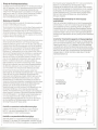
Speisung
Anschluß an Mikrofoneingänge
empfindlichkeit
Prinzip
der Hochfrequenzschaltung
und Anschluß
Von Sennheiser electronic wurde die Tonaderspeisung
die dann in DIN 45595 genormt wurde.
eingeführt,
Wie bei dynamischen Mikrofonen sind bei dieser Speisungstechnik
zum Anschluß nur zwei Adern im Mikrofonkabel erforderlich. Der
Speisestrom nimmt denselben Weg wie die Tonfrequenzspannung,
so daß die Schaltung im Mikrofon nicht galvanisch mit Masse verbunden ist. Durch diese »erdfreie Technik« ergeben sich die höchstmöglichen Werte für die Störfestigkeit.
Beim Anschluß der Sennheiser-Kondensator-Mikrofone
wird ebenso
wie bei dynamischen Mikrofonen vom Prinzip der Spannungsanpassung Gebrauch gemacht. Der Vorteil ist dabei, daß weder der
Impedanzverlauf des Mikrofonausganges
noch der des Verstärkereinganges einen nennenswerten Einfluß auf den Gesamt-Frequenzgang haben. Die Quellimpedanz der Sennheiser-KondensatorMikrofone mit Tonaderspeisung
ist so klein (etwa 8 Q bei 1000 Hz),
daß von der Eingangsimpedanz
des Verstärkers nur verlangt wird,
daß sie mindestens 400 Q beträgt. Das ist meist der Fall. Sollte
dennoch ein Eingang mit geringerer Impedanz vorliegen, so muß
man mit einem geeigneten Vorwiderstand dafür sorgen, daß das
Mikrofon mindestens 400 Q »sieht«. Die dabei auftretende
Spannungsteilung
muß natürlich berücksichtigt werden. Dieselbe
Methode wird angewandt, wenn eine höhere Ausgangsimpedanz
des Mikrofons verlangt wird. Auch in diesem Fall kann man sich
durch Vorschalten eines entsprechenden Widerstandes helfen.
Die Sennheiser-Kondensator-Mikrofone
geben r~lativ hohe
Spannungen ab, bei maximalen Schalldrüc;ken fast 1 V. Das hat den
Vorteil, daß auch bei großen Kabellängen eingekoppelte Störspannungen keine Bedeutung erlangen. Weiterhin geht auch das.
Eigenrauschen des Mikrofonverstärkers
kaum noch in das Gesamtrauschen ein. Die Mikrofone sind außerdem mit reichlich bemessenen Hochfrequenzsiebgliedern
ausgestattet, die dafür sorgen,
daß keine Hochfrequenzspannungen
auf die Mikrofonleitungen
gelangen und die gleichzeitig die Mikrofone gegen Hochfrequenzstörungen
von außen schützen. Es ist deshalb auch unter
schwierigen Verhältnissen nicht notwendig, besondere Maßnahmen, wie Doppelabschirmung
der Leitungen und hochfrequenzdichte Armaturen, vorzusehen. Sennheiser-Kondensator-Mikrofone
sind nach DIN gepolt, d. h. bei Auftreten eines Druckimpulses von
vorn auf die Kapsel tritt an Stift 1 (Stift 2 bei MKH 416 TU-3)
eine positive Spannung gegenüber Stift 3 auf. Bei der Beschaltung
der Anschlußstifte der Verstärkereingänge sollte man daher auf
die richtige Polung des NF-Signals achten.
mit hoher Eingangs-
Wenn der vorhandene Verstärker eine zu hohe Eingangsempfindlichkeit besitzt, z. B. wenn er für niederohmige dynamische Mikrofone vorgesehen ist, kann es notwendig werden, den Pegel der
Kondensatormikrofone
mit Hilfe eines Spannungsteilers
herunterzusetzen. Dieser soll in der Mikrofonleitung am Verstärkereingang
angeordnet werden. Hierdurch wird in dem eigentlichen Mikrofonkreis der hohe Pegel bewahrt, was sich günstig auf den Störabstand
auswirkt.
Anschluß an Tonaufzeichnungsgeräte
mit Speisemöglichkeit
Wenn im Verstärker eine geeignete Spannung zur Verfügung steht,
kann das Kondensatormikrofon
daraus direkt gespeist werden. Die
Spannung soll hierzu 12 V:t 2 V betragen. Sie muß so stabilisiert
und gesiebt sein, daß die Fremdspannung kleiner als 5flV und die
Geräuschspannung
kleiner als 2 flV ist. Die Stromaufnahme beträgt
etwa 6 mA, die nach Norm vorgeschriebenen
Speisewiderstände
betragen dabei 2 x 180 Q. Das heißt, es fallen etwa 2 Van den
Speisewiderständen
ab.
'---
(';
, ,
'.'
",
"
[---1
,a
--'
.l:'~
-I ~I
. ~---'I/b
1800 ,
1800
1
, c--
12VCJS
Symmetrische
Tonaderspeisung
nach DIN 45595
360Q
+12V
NF
+' f::-
-12V
Anschluß an symmetrisch-erdfreie
Mikrofoneingänge
NF
In diesem Fall verbindet man das Mikrofon mit dem Netzgerät
MZN 16 T oder einem Speiseadapter MZA 16 T und deren
Ausgang wiederum mit dem Verstärkereingang.
Anschluß an unsymmetrische
' I,a
I
'
'1,' b
3600
I:t
Mikrofoneingänge
Sehr häufig stehen nur unsymmetrische Verstärkereingänge zur
Verfügung, z. B. bei vielen HiFi-Tonbandgeräten. In diesem Fall erdet
man einen Punkt des Tonfrequenzausganges
(vorzugsweise Stift 3).
3
(":---7--"
""
Unsymmetrische
Tonaderspeisung
4
DIRECTIONALSTUDIO
MICROPHONE MKH 416 T
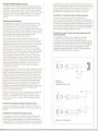
Richtdiagramm
90"
90"
250 Hzl_.500 Hz~
1000 Hz -
150"
150"
180"
2000
4000
8000
16000
Hz Hz-Hz -Hz -.
Frequenzkurve
f-
==
-
f-
110dB
-f--
-=
--t-
t'"
"
"'"
'00
""'"
=
=
-
-",
Solifrequenzgang mit Toleranzschema
Oelivery: 1 microphone
Jedem Mikrofon legen wir das Original-Meßprotokoll bei,
gemessen von 50 . . . 20000 Hz.
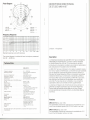
General Description
MKH 416 T-3
40...20000 Hz
0 ruckgradienten-Interferenzemptänger
Richtcharakteristik . . . . . . . . . . .. Superniere-Keule
Feld-Leerlauf-Übertragungsfaktorbei 1000 Hz20 mV/Pa:t1 dB
ElektrischeImpedanz bei 1000 Hz.
ca. 8..Q,symmetrisch, erdfrei
Nennabschlußimpedanz. . . . . .
;';;400.Q(200.Qbis 20 Pa)
Geräuschspannungsabstand nach
ca. 72 dB
DIN45590, bezogen auf 1 Pa
Aussteuerungsgrenze.
30 Pa (124 dB)
12V:t2V
Speisespannung
ca. 6 mA
Speisestrom.
.
- 10° C bis + 70° C
Temperaturbereich.
Stecker.
3poliger Normstecker nach
Übertragungsbereich. .
AkustischeArbeitsweise.
Beschaltung
Anschlußkupplung
Abmessungen
Gewicht
Abweichungen für
Stecker. . .
Beschaltung
Anschlußkupplung
Abmessungen
Gewicht
DIN 41524
1 : NF, 2 : Gehäuse, 3 : NF
nach DIN 45595
3polige verschraubbare Normkupplung nach DIN 41 524,
z. B. T 3261 001
19 mm <1>,235mm lang
160 g
MKH 416 TU-3
3poliger Cannon-Stecker XLR-3
1 : Gehäuse, 2 : NF, 3 : NF nach
IEC-Normvorschlag
(Publication 268-14 B)
3polige Cannon-Kuppl. XLR-3-11C
19 mm <1>,250mm lang
175 g
Änderungen, vor allem zum technischen Fortschritt, vorbehalten.
5
The directionalstudio microphone MKH416 T is a transistorized RF
condenser microphone.The oe voltage necessary foroperation is
fed through the conductors of the connecting cable (A-B powering
according
to the German standard
OIN 45595).
The MKH 416 T represents a combination of apressure gradient
transducer and an interference microphone. The directional
characteristic is super-cardioid at low and medium frequencies, at
higher frequencies the directional pattern is club-shaped. The
microphones susceptibility to wind and pop noises is low due to
the relative high acoustical membrane pressure. The MKH 416 T
can be employed as a microphone for soloists or for commentarv
purposes without using an additional popshield. However, for outdoor work the use of a windshield is recommended.
The frequency response is maintained to have a slight increase at
the high frequencies. The so-called close-miking effect is low with
this microphone. Therefore, the MKH 416 T gives a weil balanced
sound sensation even it is used close up.
Models
MKH 416 T-3 (Art.-No.1565)
12 V AB-powering, with 3-pin OINplug, screwable (OIN41 524).
Finish: matt black.
MKH 416 TU-3 (Art.-No.1567)
12 V AB-powering,with 3-pin XLR-plug.Finish: matt black.
6
Principleof High Frequency Circuit
The capsule 01a RF condenser microphone presents, contrary to
low Irequency circuits, a low impedance output. Instead 01 the high
polarization voltage normally required, a high Irequency capsule
needs only a high Irequency voltage 01 about 10 volts, wh ich is produced bya built-in low noise oscillator (8 MHz). The low capsule
impedance leads to a high performance reliability 01 the microphones.
Powering and Connection
Sennheiser electronic introduced A-B powering, which was then
standardised in DIN 45595. As with dynamic microphones, only .
two wires are required to connect the microphone when this
powering system is being used. The operating current is led along
the same wires as the audio Irequency signal, so that the circuitry in
the microphone does not have to be connected to earth. Because
01this earth Iree technique the highest possible values 01
immunity Irom noise or disturbance are achieved.
The connection 01 Sennheiser condenser microphones and
dynamic microphones as weil is carried out using the principle 01
voltage matching. The advantages 01this system are that neither
impedance vBriations 01 the microphone output nor 01the amplilier
input exercise a noticeable inlluence on the total Irequency
response. The source impedance 01the Sennheiser condenser
microphones with A-B powering is so low (approx. 8 Q at 1000 Hz)
that an amplilier input with an impedance 01 at least 400 Q will be
suitable. This is usual in the majority 01 cases. However, il the
input impedance is smaller than 400 Q, a resistor 01 appropriate
value should be placed in series with the microphone so that it
"sees" at least 400 Q. The voltage division caused by this series
resistor must 01 course be considered. The same method can be
used when a highter output impedance 01the microphone is
demanded. In this case again aseries resistor can be used to
provide correct matching.
Sennheiser condenser microphones produce relatively large output
voltages, these can be up to 1 volt with maximu[TI sound pressure
levels. This has the advantage that even with long cables induced
interference signals can be disregarded. Also the internal noise
produced by the microphone does not contribute to the total noise
level. The microphones are litted with high Irequency lilters, which
ensure that no high Irequency signals Irom the microphone can
affect the external circuitry, and also that the microphone itsell is
protected lrom high Irequency disturbance. It is, therelore, not
necessary, even under the most difficult conditions, to take special
precautions such as double screening 01 the cables or the
provision 01 high Irequency lilters.
Sennheiser condenser microphones are polarised according to DIN'
standard i. e. when pressure signal strikes the capsule Irom the
Iront, pin 1 (pin 2 lor MKH 416 TU-3) goes positive with relerence
to pin 3. This should be considered when the amplilier input plug
is being wired.
Connection
to balanced,
floating microphones
to unbalanced
microphone
inputs
In many cases, lor example most tape recorders, the input socket
is unbalanced. In this case one pin 01the balanced microphone
output has to be earthed (prelerably pin 3). When using the power
supply unit MZN 16 T an unbalanced operation only is possible after
a modilication 01the power supply unit. Apart lrom cases where the
7
Connection
to microphone
inputs with high sensitivity
If the unit being used has a very high input sensitivity, i. e,
when it is normally intended lor use with dynamic microphones, it
can be necessary to reduce the output voltage Irom the microphone
by means 01 a voltage divider, wh ich should be built into the microphone cable at the amplilier input. By this means the large signal on
the microphone cable is maintained up to just belore the amplilier,
which results in a increased signal to noise ratio.
Connection to mixer and sound recording
powering facilities
equipment
with
II an appropriate voltage source is available the condenser
microphone can be powered directly. The voltage should
be 12 volts :t 2 volt. It should be so stabilised and liltered, that the
unweighted noise voltage is less than 5 flV and that the weighted
noise components are less than 2 flV. The current consumption 01
the microphone is approximately 6 mA. According to the DIN
standard the resistors should be 2 x 180 Q. This means that the
voltage drop across the resistors is approx. 2 V.
'---
n, ,
,,,---y
,,
,,
,,
i L
,,
,
,,
,,
,
! ---1
====l ::==~
180Q ,
12V
Balanced
A-B powering
according to DIN 45595
i
,,,
,,
,,
i
L
n'
1
L_-
S
3600
:,
---r
(j
,
+12V
NF
,,
,,
,,
+'~
inputs
In this case the microphone is simply connected to the input 01 an
amplilier via a powering adapter MZA 16 T or the power supply unit
MZN 161.
Connection
microphone is being used for professional studio purposes, this is not
critical, as the large output voltage of the microphone combined with
its low output impedance provides a large signal to noise ratio. Care
should be taken, however, that no multiple ground circuits are
lormed when the microphones are mounted on tripods etc.
,,,---y
,
i'
,,
,,,
-12V
,
;2' "
,
i---L
Unbalanced
,
i
NF
f:t
I
T'b
A-B powering
8
MICROPHONE DIRECTIONNEL
OE STUDIO MKH 416 T
Polar Diagram
90'
250 HzL_.500 Hzr
1000 Hz -
2000
4000
8000
16000
180'
-
Hz
Hz Hz Hz-'
-
Frequency Response
=
=
"
110dS
'"
-
--- f--If,
,
-..=
--
Livraison:
1 microphone
,='"
Standard response curve with tolerances
The original diagram is included with each microphone, measured
from 50 . . . 20000 Hz.
MKH 416 T-3
Frequeney response
Operating prineiple
Direetional eharaeterislie
Sensltlvityat 1000 Hz .
Impedanee at 1000 Hz
Nominalload.
. . . . . . . . . . . . .
Signal to noise ratio to DIN 45590 refered
to 1 Pa . . . .
Maximal s. p. I.
Supply voltage
Supplyeurrenl
. .
Temperature range
Output plug
Wlrlng
Cable eonneelor
Dimensions
Weight
Specitic da ta tor
Output plug
Wiring
Cable eonneetor
Dimensions
Weight
40...20000
Hz
pressure gradienl-interterenee
transdueer
super-eard ,oid-Iobe
20 mV/Pa:t 1 dB
approx.8 Q balaneed, earth free
'" 400 Q (200 Q up 1020 Pa)
approx. 72 dB
30 Pa (124 dB)
12V:t2V
approx. 6 mA
- 10' C to + 70° C
3 pin standard plug to DIN 41 524
1 : Audio. 2 : Earth. 3 : Audio
10DIN 45595
3 pin standard eonneetor to
DIN 41 524 e. g. T 3261 001
Le microphone directionnel de studio MKH416 Test un microphone
electrostatique Ei.haute-frequence. La tension continue necessaire
au fonctionnement du micro de 12 V est amenee par les deux
conducteurs de modulation de cable de raccordement (alimentation
par conducteurs de modulation selon DIN45595).
Le MKH416 Test une combinaison d'un capteur Ei.gradient de pression et d'un capteur d'interferences. La directivite est super-cardio'ide
pour les basses et moyennes frequences et prend la forme d'un
lobe pour les hautes frequences. Grace Ei.une pression acoustique
relativement elevee pour la membrane, la sensibilite au effets du
vent et aux effets «pop» est insignifiante. Le MKH 416 T peut donc
etre utilise pour les solistes et les reportages, sans bonette de
proximite.Pour les prises de son Ei.I'exterieur,nous conseilIons
cependant d'utiliser une bonnette anti-vent supplementaire.
La reponse en freql,Jencedu microphone est conyue de fayon Ei.
presenter une legere accentuation pour les hautes frequences.
Comme I'effetde proximiteest tres faible pour ce micro,I'image
sonore equilibree est conservee meme Ei.une tres faible distance
voix-micro.
19 mm W. 235 mm long
160 9
MKH 416 TU-3
3 pin Cannon plug XLR-3
1 : Earth. 2 : Audio. 3 : Audio to
proposed IEC standard
(Publieatlon 268-14 B)
eonneelor XLR-3-11 C
19 mm W,250 mm long
175 9
We reserve the fight 10alter speeifieations, in partieular wilh regard 10leehnieal
improvements.
9
Description
Versions
MKH 416 T -3 (No d'art. 1565)
Pour alimentation Ei.travers les conducteurs de modulation de 12 V.
Avecfiche normaliseetripolaire(DIN41 524). Surface: noir mate.
MKH 416 TU-3 (No. d'art. 1567)
Pour alimentation Ei.travers les conducteurs
de modulation
Avec fiche XLR tripolaire. Surface: noir mate.
de 12 V.
10
Montage
haute
frequence
garantissent un rapport signal/bruit suffisant. Veillez cependant a ne
pas faire de mises a la terre multiples lors de I'utilisation de pieds
de micro.
Contrairement au montage basse frequence, la capsule d'un micro
electrostatique a haute frequence presente une faible impedance. A
la place de la tension de polarisation relativement elevee, la capsule
n'est soumise qu'a une faible tension d'environ 10 volts, fournie par
un oscillateur (8 MHz) a faible bruit de fond. La faible impedance du
systeme mene a une haute fiabilite des microphones.
Alimentation
Pour le branchement de ses microphones electrostatiques,
Senn heiser utilise, comme pour les microphones dynamiques, le
principe de I'adaptation en tension. De ce fait, ni les variations
d'impedance du microphone, ni celles de I'amplificateur n'ont
d'influence sensible sur la courbe de reponse. L'impedance de
source des microphones electrostatiques Sennheiser est tellement
faible (environ 8 Q a 1000 Hz) que la seule exigence a I'amplificateur est que son impedance soit au moins 400 Q. Toutefois, si
I'impedance d'entree de I'amplificateur est inferieure, il faut choisir
une resistance additionnelle convenant pourque le micro «voie».au
moins 400 Q. La division de tension qui s'ensuit doit evidement
etre prise en consideration. La meme methode est employee si on
a besoin d'une impedance micro plus elevee. Dans ce cas aussi
une resistance additionelle mene a une adaptation correcte.
Les micros electrostatiques Sennheiser donnent des tensions de
sortie relativement elevees, pour des pressions acoustiques maximales, presque 1 V. L'avantage en est que, meme pour des cables
longs, les tensions parasitaires n'ont aucune influence. En outre,
I'influence du bruit de fond de I'amplificateur du micro est pratiquement inexistante. Des plus, tous ces micros Sennheiser so nt
equipes de filtres haute frequence dimensionnes genereusement.
Ces filtres eliminent les tensions parasites HF de la ligne et
protegent les microphones contre de champs HF exterieurs. Meme
pour des conditions difficiles de transmission, il n'est pas necessaire
de prevoir de protections speciales (double blindage de lignes,
materiel anti-HF, etc.).
La polaritE~des micros est conforme aux normes DIN c. a. d. si une
impulsion de pression touche la capsule de front, la broche 1
(broche 2 pour MKH 41 6 TU-3) possede une tension positive par
rapport a la broche 3. Lors du cablage des broches de I'amplificateur
veillez donc a la polarite correcte du signal BF.
a des entrees
micro symetriques
s'il est prevu
':"
Comme pour les microphones dynamiques, cette technique n'exige
que deux conducteurs. Le chemin du courant d'alimentation est
identique a celui de la tension audiofrequence (AF), ce qui permet
d'eviter que les circuits du micro soient galvaniquement connectes
a la masse. Cette technique «sans mise a la masse» garantit une
excellente protection anti-parasites.
a la terre
Si I'appareilpresent possede une sensibilite trop elevee, (p. ex.
pour des micros
dynamiques
a basse
impedance)
a I'aide
il est parfois necessaire de diminuer la tension du micro
et branchement
C'est Sennheiser qui a introduit I'alimentation a travers les conducteurs de modulation. Ce procede a ete normalise par DIN 45595.
Branchement
Branchement a des entrees micro a haute sensibilite
et sans mise
Dans ce cas on relie le micro a I'entree de I'amplificateur par I'intermediaire de I'alimentation secteur MZN 16 T ou d'un adapteur
d'alimentation MZA 16 1.
d'un diviseur de tension.Celui-ci doit etre incorpore au cable du
micro a I'entree de I'amplificateur.Par ces moyens, le niveau eleve
est maintenujusqu'a I'entreede I'amplificateur,ce qui est propice
au rapport signal/bruit.
Branchement ades pupitres de melange et des appareils
d'enregistrement
avec possibilite d'alimentation
Si I'appareil possede une tension convenant, le micro electrostatique
peut en etre alimente directement. La tension devrait etre
oe 12 V::t 2 V. Elle doit etre stabilisee et filtree de teile maniere que
la tension non ponderee soit inferieure 'ci 5 /lV et que la tension
ponderee inferieure a 2 /lv. Le courant d'alimentation des micros
electrostatiques MKH de Sennheiser se situe a environ 6 mA, la
valeur des resistances d'alimentation standardisees est de
2 x 180 Q.Par consequent, les deux resistances subissent une
chute de potentiel de 2 V.
,---rn---n:
,,
,
,,
,,
'
,,
,
,,
,,
r~~,
, ,
:, I I,
1800,
:-n-L-nn-n'
,
---
Alimentation symetrique
par conducteurs
de modulation selon DIN 45595
3600
:,
,
,,,
,,
,
T-nn_n,
'-n-T-
nnn__'
'''
'
''
'
+12V
NF
+' f::-
'
-12V
Branchement
a des entrees
micro asymetriques
Tres souvent on ne dispose que d'amplificateurs a entree asymetrique p. ex. pour beaucoup de magnetophones HiFi. Dans ce cas on
met tout simplement a la masse une des broches de la sortie BF
(de preference broche 3).' Pour I'operation asymetrique en utilisant
le MZN 16 T I'alimentation secteur doit etre modifiee. En dehors des
studios, cette solution est peu critique. Le niveau eleve en combinaison avec I'impedance interne faible du micro electrostatique
11
NF
I:;-
'r)b
Alimentation asymetrique conducteurs de modulation
12
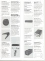
Zubehör! Accessories!
Accessoires
Diagramme
de directivite
Klemmhalterung MZQ 415
Passend zum MZG 415.
Nimmt Mikrofone mit einem
Schaftdurchmesser
von 19 mm
auf.
90°
90°
250 Hzl_.500 Hzr
1000 Hz -
Clamp MZQ 415
Suitable far MZG 415. Takes
microphones with a max. shaft
diameter of 19 mm.
2000 Hz 4000 Hz-8000 Hz -16000 Hz-"
180°
Courbe de reponse
r
--
-
t-
Pince de fixation MZQ 415
Destinee auf MZG 415.
S'adapte ades microphones de
19 mm cf;de ti ge au maximum.
Gelenkarm MZG 415
Der Gelenkarm ermöglicht es,
den Tischfuß MZT 441 zusammen mit der Klemmhalterung
MZQ 415 oder der Federhalterung MZS 415 für das
MKH 416 Teinzusetzen.
Swivel Mount MZG 415
The swivel mount gives the possibility to use the desk stand
MZT 441 together with the
microphone clamp MZQ 415 or
the shock mount MZS 415 far
the MKH 416 T.
Bras articule MZG 415
Le bras articule permet de
combiner le pied de table
MZT 441 avec la fixation rapide
MZQ 415 ou la suspension
elastique MZS 415 pour le
MKH 416 T.
n
E ! 10dB
'"
"
"O
"""
""'"
t-
-"=
t-
-
t-
-
''""'°
-".
Courbe de reponse avec tolerances
Chaque microphone est livre avec I'original du proces-verbal des
mesures entre 50 et 20000 Hz
~
MKH 416 T-3
Bande passante.
.
Principe acoustique .
Directivite . . ..
..........
Facteur de transmission a vide a 1000 Hz
Impedance a 1000 Hz. . . . . .
Impedance nominale de charge. . . .
Rapport signal/bruit (seion DIN 45590)
par rapport a 1 Pa. . .
Niveau max. a 1000 Hz
Tension d'alimentation .
Consommatlon. . . .
Piage de temperatures
Connecteur.
Brochage
Connecteur pour cable de raccordement
Dimensions
POlds
Deviation~ pour
Connecteur.
Brochage
Connecteur pour cable de raccordement
Dimensions
POlds
40...20000
Hz
capteur a gradient de pression et
capteur d'interterences
super-cardio'ide - lobe
20 mV/Pa:t 1 dB
env. 8 Q, symetrique, sans masse
~ 400 Q (200 Q jusqu'a 20 Pa)
appx. 72 dB
30 Pa (124 dB)
12V:t2V
appx. 6 mA
- 10° C.. + 70° C
fiche tripolalre normailsee
DIN 45524
1 = BF, 2 = boitier, 3 = BF
selon DIN 45 595
conecfeur tripolaire vissable
normalise DIN 41 524
p. ex. T 3261 001
19 mm p, longueur 235 mm
160 g
MKH 416 TU-3
fiche tripolaire Cannon XLR-3
1 = boitier, 2 ~ BF, 3 ~ BF selon
proposition de standardisation IEC
(Publication 268-14 B)
connecteur Cannon tripolaire
XLR-3-11 C
19 mm p, longueur 250 mm
175 g
Modifications, sourtout.dans I'lntere! du progres technique, reservees.
13
Federhalterung MZS 415
Die Federhalterung kann auf alle
Stative, Ausleger usw. mit %"Gewinde aufgeschraubt werden
und vermindert Aufnahmestörungen durch Trittschalt oder
Bodenschwingungen.
Innendurchmesser
19 mm,
Länge 80 mm.
Shock Mount MZS 415
The shock mount can be
connected to alt tripods, booms,
etc. with %" threads and
prevents recordings being
disturbed by footfalt far other
strong mechanical disturbances.
Innerdiameter 19 mm,
Length 80 mm.
Suspension elastique
MZS 415
Elimine les perturbalions
causees par les bruits de pas
ou les vibrations du sol. Peut
etre vissee sur tous les pieds de
micro, pieds de table et perches
a taraudage %". Diametreinterieur 19 mm.
Longueur 80 mm.
14
TischfuB MZT 100
Stabiler, feststehender Tischfuß
für den Studio-Betrieb. Sehr
hohe Körperschalldämpfung.
Mit %"-Befestigungsschraube.
Desk Stand MZT 100
Very stable desk stand for studio
use. Features very good
handling noise sUBpression.
Fixing screw with 18"thread.
Pied de table MZT 100
Pied de table de studio robuste
et stable. Amortissement tres
efficace de vibrations et bruits
ambiants.. Avec vis de fixation
a%".
Windschutz-Kombination
MZW 426, MZS 416, MZP 816
Die Kombination besteht aus
dem bruchsicheren und leichten
Windschutzkorb MNJ 426, der
Federhalterung MZS 416 und
dem im Neigungswinkel verstellbaren Pistolengriff MZP 816.
Die Kombination ist vor allem für
den Reportageeinsatz im Freien
geeignet und zeichnet sich
durch einfache Handhabung
und gute Körperschall- und
Winddämpfung
aus.
Windscreen-combination
MZW 426, MZS 416, MZP 816
This combination consists of the
robust, light windscreen basket
MZW 426, shock mount
MZS 416 and the inclinable
pistol grip MZP 816. The
combination is particularly weil
suited for outdoor reporting use
and features easy handling and
insensitivity to wind and
handling noise.
Combinaison anti-vent
MZW 426, MZS 416, MZP 816
Gette combinaison est composee de la protection totale
anti-vent incassable MNJ 426,
de la fixation a suspension
MZS 416 et de la poignee
reglable MZP 816. Gelte combinaison est destinee pour les
reportages !3.I'exterieur. Elle
garantit un maniement aise et
une protection efficace contre
les bruits du vent.
Nahbesprechungs-und
Windschutz MZW 415
Schaum netz-Windschutz
MKH 416.
für
Windscreen and Pop Filter
MZW 415
Sponge windscreen for
MKH 416.
Bonnette de proximite et
anti-vent MZW 415
Gelte bon nette en mousse
acoustique speciale est conc;;ue
specialement pour le microphone MKH 416.
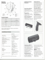
Netzgerät MZN 16 T und
MZN 16 T-U
Für den gleichzeitigen Betrieb
von zwei Mikrofonen. Das Gerät
kann an beliebiger Stelle in der
Anschlußleitung eingeschaltet
werden. Modell T-U mit XLRAnschlüssen. Abmessungen
in mm: 168 x 120 x 50.
Power supply MZN 16 T and
MZN 16 T-U
For simultaneous powering of
two microphones. The unit can
be included in the microphone
cable at any point. Model T-U
with XLR connectors.
Dimensions in mm:
168 x 120 x 50.
Alimentation secteur
MZN 16 T et MZN 16 T-U
Pour I'alimentation simultanee
de deux microphones. Le bloc
d'alimentation peut etre intercale
en n'importe quel point du
cordon du micro. Modele T-U
avec connecteurs XLR.
Dimensions en mm:
168 x 120 x 50.
Speiseadapter
MZA 16 T
Zur netzunabhängigen Spannungsversorgung von einem
tonadergespeisten Kondensatormikrofon nach
DIN 45595.
Powering adapter
MZA 16 T
For voltage supply of one
AB-powered condenser
microphone according to
DIN 45595.
Adapteur d'alimentation
MZA 16 T
TischfuB MZT 441
Stabiler, feststehender Tischfuß. Kann mit dem Gelenkarm
MZG 415 und der Klemmhalterung MZQ 415 oder der Federhalterung MZS 415 kombiniert
werden.
Desk Stand MZT 441
Stable desk stand. May be
combined with the swivel
mount MZS 415.
Pied de table 441
Pied de table robuste et stable.
Gombinaison avec le bras
articule MZG 415 et la fixation
rapide MZQ 415 ou la
suspension elastique MZS 415.
15
Pour I'alimentation d'un
microphone electrostatique
independante de reseau
selon DIN 45595.
AnschluBkabel KA 7 U
Beidseitig mit XLR-Steckververbindern ausgerüstet.
Länge: 7,5 m.
Connecting cable KA 7 U
Fitted at both ends with XLRconnectors. Length: 7.5 m
Cäble de raccordement
KA7U
Longueur 7,5 m, equipe aux
bouts de connecteurs Gannon
XRL-3-12 C
16
Anschlußkabel KA 1 und KA 7
Dreiadrig abgeschirmte Kabel
mit 3poligem Normstecker nach
DIN 41 524 und 3poliger Normbuchse. Länge des Kabels KA 1 :
1,5 m. Länge des Kabels KA 7:
7,5 m.
Anschlußkabel KA 7 UN
Geeignet für alle SennheiserMikrofone mit XLR-Steckverbindern (System Cannon).
Geräteseitig 3pol., verschraubbarer Normstecker (z. B.
T 3260001). Länge: 7,5 m.
Anschlußkabel KA 1 und KA 7
Dreiadrig abgeschirmte Kabel
mit 3poligem Normstecker nach
DIN 41 524 und 3poliger Normbuchse. Länge des Kabels KA 1 :
1,5 m. Länge des Kabels KA 7:
7,5m.
Anschlußkabel KA 7 UN
Geeignet für alle SennheiserMikrofone mit XLR-Steckverbindern (System Cannon).
Geräteseitig 3pol., verschraubbarer Normstecker (z. B.
T 3260001). Länge: 7,5 m.
Connecting Cable
KA 1 and KA 7
Tripie conductor shielded cable
fitted with 3-pin standard plug
according to DIN 41 524 and
3-pin standard socket. Length of
cable KA 1: 1.5 m. Length of
cable KA 7: 7.5 m.
Connecting Cable KA 7 UN
Suitable for all Senn heiser
microphones equipped with
XLR-connectors (Cannon). The
cable is fitted with a 3-pin XLRconnector on one end and a
3-pin screwable standard plug
(e. g. T 3260001) on the other
end. Length of cable: 7.5 m.
Cäble de raccordement
KA 7 UN
Pour taus microphones
Sennheiser avec raccord a
fiche XLR (Cannon). Equipe cote
appareil d'une connecteur
tripolaire vissable (p. e.
T 3260001).
Longueur de cable: 7,5 m.
Connecting Cable
KA 1 and KA 7
Connecting Cable KA 7 UN
Suitable for all Sennheiser
microphones equipped with
XLR-connectors (Cannon). The
cable is fitted with a 3-pin XLRconnector on one end and a
3-pin screwable standard plug
(e. g. T 3260001) on the other
end. Length of cable: 7.5 m.
Cäble de raccordement
KA 7 UN
Pour taus microphones
Senn heiser avec raccord a
fiche XLR (Cannon). Equipe Gote
appareil d'une connecteur
tripolaire vissable (p. e.
T 3260001).
Longueur de cable: 7,5 m.
Cäble de raccordement
KA1 etKA7
Cable blinde a trois fils et
equipe d'une fiche tripolaire
normalisee DIN 41 524 et d'une
douille a trois poles. Longueur
du cable KA 1: 1,5 m.
Longueur du cable KA 7: 7,5 m.
r
K:J'
L
T 3261 001
l
'~
~
T 3260 001
~n:Qi
L
XRL-3-11C
Tripie conductor shielded cable
fitted with 3-pin standard plug
according to DIN 41 524 and
3-pin standard socket. Length of
cable KA 1 : 1.5 m. Length of
cable KA 7: 7.5 m.
Cäble de raccordement
KA1 etKA7
Cable blinde a trois fils et
equipe d'une fiche tripolaire
normalisee DIN 41 524 et d'une
douille a trois poles. Longueur
du cäble KA 1: 1,5 m.
Longueur du cable KA 7: 7,5 m.
r
l
k:J'
,
I
L
T
,01,
I
~
T 3260 001
3261 001
~n:Qi
L
XRL-3-11C
J
J
T 3260 001
T 3260 001
Anschlußkabel
KA 7 U
Beidseitig mit XLR-Steckververbindern ausgerüstet.
Länge: 7,5 m.
Connecting cable KA 7 U
Fitted at both ends with XLRconnectors. Length: 7.5 m
Cäble de raccordement
KA7U
Longueur 7,5 m, equipe aux
bouts de connecteurs Cannon
!\V
L
XRL-3-11
c
17
~i
J
XRL-3-12C
18