1
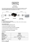
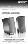
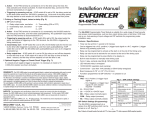
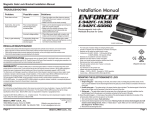
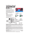
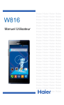
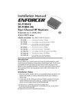
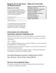
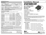
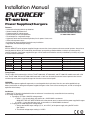
Installation Manual
ENFORCER
®
ST-series
Power Supplies/Chargers
Features:
• Automatic recharging of back-up batteries.
• Several models to choose from.
• Programmable DC voltage output.
• Built-in battery short-circuit protection.
• Fused output for a regulated charge.
• Automatic switch-over to the backup battery if main power is lost or cut.
• LEDs indicate power status.
• Includes foam tape and battery leads for easy installation.
• Regulated and filtered output voltage.
ST-2406-2AQ shown
What it is:
SECO-LARM’s ST-series of power supplies/chargers ensure that alarm systems and access control systems always have
enough power to do their job. Protected by fused output, input polarity protection diodes, and back-up battery polarity
reverse protection, these power supplies/chargers can be used to maximize the security and efficiency of nearly any alarm
or access control installation.
Model #
ST-1206-1.5AQ
ST-2406-2AQ
ST-2406-3AQ
ST-2406-5AQ
ST-2406-7AQ
ST-2406-10AQ
DC Voltage
6, 12
6, 12, 24
6, 12, 24
6, 12, 24
6, 12, 24
6, 12, 24
Current (continuous)
1.5A
1.5A
2.5A
4.0A
7.0A
9.0A
Current (peak)
2.0A
2.0A
3.0A
5.0A
7.5A
10.0A
Current Output (maximum charge)
6 V = 200mA, 12 V = 400mA
6 V = 180mA, 12 V = 350mA, 24 V = 700mA
6 V = 180mA, 12 V = 350mA, 24 V = 700mA
6 V = 180mA, 12 V = 350mA, 24 V = 700mA
6 V = 180mA, 12 V = 350mA, 24 V = 700mA
6 V = 180mA, 12 V = 350mA, 24 V = 700mA
PCB Size
27/8” x 21/4” x 1”
27/8” x 21/2” x 13/8”
33/8” x 2 7/8” x 15/16”
33/4” x 2 7/8” x 19/16”
51/2” x 51/8” x 211/64”
51/2” x 51/8” x 211/64”
(73 x 57 x 25 mm)
(73 x 64 x 35 mm)
(81 x 73 x 33 mm)
(95 x 73 x 40 mm)
(140 x 130 x 55 mm)
(140 x 130 x 55 mm)
Fused Output:
The ST-1206-1.5AQ comes with a 3A fuse. The ST-2406-2AQ, ST-2406-3AQ, and ST-2406-5AQ models come with a 5A
fuse. The ST-2406-7AQ and ST-2406-10AQ come with a 10A fuse. Use only the correct fuses to prevent short circuits
and damage to the power supplies/chargers or the alarm access control panel.
WARNING:
Connect these power supplies/chargers only to a rechargeable back-up battery. Use of a non-rechargeable back-up
battery could result in damage to the power supplies/chargers or the alarm access control panel, as well as leakage or
explosion of the battery.
Installation:
1. Mount the PC board in the desired location or enclosure. It must be easily accessible for future servicing.
2. DC Power Output Setting:
a. To program ST-1206-1.5AQ DC voltage output:
1. 6VDC — Cut the wire loop, and connect to a 12VAC/20VA transformer.
INSULATE THE CUT WIRE LEADS so that they do not come in contact with the power supplies/chargers.
2. 12VDC — Leave the wire loop uncut, and connect to a 16VAC/40VA transformer.
b. To program ST-2406 Series DC voltage output:
1. Set the desired DC output voltage ( 6, 12, or 24 VDC ) of the power supply using the DIP switch.
See Table 2.
2. The default voltage output setting is 12 VDC.
Note: Products with model number that ends with "Q"or have a green “Q” sticker represents RoHS compliant products.
Figure 2 – ST-2406 Series wiring diagram
Figure 1 – ST-1206-1.5AQ wiring diagram
(black)
(red)
To back-up battery negative (-) input
To back-up battery positive (+) input
Wire loop
1AC I/P 2
3DC O/P 4
Green AC Input LED
Red Led
indicator
Red DC Output LED
To alarm or access control
panel VDC positive (+) input
To Class-II
transformer
VAC outputs
AC
To alarm or access control
panel VDC negative (-) input
+DC -
- BAT +
To Class-II
transformer
VAC outputs
To back-up battery positive (+) input
To back-up battery negative (-) input
To alarm or access
control panel VDC
positive (+) input
To alarm or access control
panel VDC negative (-) input
3. Connect the wirings to their respective terminals (see Figure 1 and 2).
NOTE:
a. Before connecting any external devices, temporarily power up the unit and measure the DC output voltage
to avoid damage to devices. Then disconnect power before connecting external devices.
b. LED status — for ST-1206-1.5AQ, Red LED on indicates connections to AC power.
for ST-2406 series, see Table 3.
WARNING:1. Using a higher AC input than recommended may damage the unit.
2. When a power supply/charger is used at its maximum load for an extended
period of time, the heatsink portion of the power supply/charger will be very hot.
3. DO NOT USE METAL SPACERS TO MOUNT THE POWER SUPPLY’S PC BOARD.
4. Measure DC output before connecting devices.
Table 1:
Transformer selection table:
Output voltage
ST-1206-1.5AQ
ST-2406-2AQ
ST-2406-3AQ
ST-2406-5AQ
ST-2406-7AQ
ST-2406-10AQ
6VDC
12VAC/20VA
12VAC/20VA
ST-UV24-W50Q
24VAC/50VA
ST-UV16-W100Q
16VAC/100VA
ST-UVDA-W180Q
24-28VAC/180VA
ST-UVDA-W180Q
24-28VAC/180VA
12VDC
16VAC/40VA
16VAC/40VA
ST-UVDA-W100Q
24-28VAC/100VA
ST-UV16-W100Q
16VAC/100VA
ST-UVDA-W180Q
24-28VAC/180VA
ST-UVDA-W180Q
24-28VAC/180VA
24VDC
N/A
ST-UV24-W50Q
24VAC/50VA
ST-UVDA-W100Q
24-28VAC/100VA
ST-UVDA-W180Q
24-28VAC/180VA
24-28VAC/210VA
ST-UV28-T350Q
28VAC/350VA
Table 2:
To program DC voltage output:
Voltage
6V
12V
24V
SW1
ON
OFF
OFF
SW2
OFF
OFF
ON
* For ST-1206-1.5AQ model. See point 2 under Installation.
Table 3:
LED status for ST-2406 series:
Green LED
ON
OFF
ON
OFF
Red LED
ON
ON
OFF
OFF
Status
Normal
No VAC input
No VDC output
No VAC input and VDC output
NOTICE: The information and specifications printed in this manual are current at the time of publication. However, the SECO-LARM policy is one of continual development and
improvement. For this reason, SECO-LARM reserves the right to change specifications without notice. SECO-LARM is also not responsible for misprints or typographical errors.
Copyright © 2008 SECO-LARM U.S.A., Inc. All rights reserved. This material may not be reproduced or copied, in whole or in part, without the written permission of SECO-LARM.
WARRANTY: This SECO-LARM product is warranted against defects in material and workmanship while used in normal service for a period of one (1) year from the date of sale to
the original consumer customer. SECO-LARM’s obligation is limited to the repair or replacement of any defective part if the unit is returned, transportation prepaid, to SECO-LARM.
This Warranty is void if damage is caused by or attributed to acts of God, physical or electrical misuse or abuse, neglect, repair, or alteration, improper or abnormal usage, or faulty
installation, or if for any other reason SECO-LARM determines that such equipment is not operating properly as a result of causes other than defects in material and workmanship.
The sole obligation of SECO-LARM, and the purchaser’s exclusive remedy, shall be limited to replacement or repair only, at SECO-LARM’s option. In no event shall SECO-LARM be liable
for any special, collateral, incidental, or consequential personal or property damages of any kind to the purchaser or anyone else.
SECO-LARM® U.S.A., Inc., 16842 Millikan Avenue, Irvine, CA 92606
Tel: 800-662-0800 / 949-261-2999 Fax: 949-261-7326
Website: www.seco-larm.com
E-mail: [email protected]
MuST12-2406Q_084.pmd
Order Part #763-074-8%
PITSW1