1
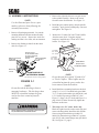
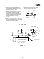
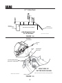
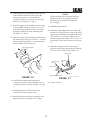
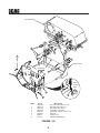
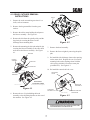
THIS MANUAL CONTAINS THE OPERATING
INSTRUCTIONS AND SAFETY INFORMATION FOR YOUR SCAG ACCESSORY. READING THIS MANUAL WILL PROVIDE YOU
WITH MAINTENANCE AND ADJUSTMENT
PROCEDURES TO KEEP YOUR ACCESSORY
PERFORMING TO MAXIMUM EFFICIENCY.
THE SPECIFIC MODELS THAT THIS BOOK
COVERS ARE CONTAINED ON THE INSIDE
COVER. BEFORE OPERATING YOUR MACHINE, PLEASE READ ALL THE INFORMATION ENCLOSED.
OPERATOR’S MANUAL
MODEL GC-STT-V
PART NUMBER 03181
WARNING
FAILURE TO FOLLOW SAFE OPERATING PRACTICES
MAY RESULT IN SERIOUS INJURY.
* Keep all safety shields in place.
* Before performing any maintenance or service, stop the machine and
remove the spark plug wire.
* If a mechanism becomes clogged, stop the engine and wait for all moving
parts to come to a complete halt before cleaning.
* Keep hands, feet and clothing away from power-driven parts.
* Read this manual completely as well as the Operator's Manual that came
with your mower.
* Keep others off the tractor (only one person at a time).
REMEMBER - YOUR MOWER IS ONLY AS SAFE AS THE OPERATOR!
Hazard control and accident prevention are dependent upon the awareness,
concern, prudence, and proper training of the personnel involved in the operation, transport, maintenance, and storage of the equipment.
This manual covers the operating instructions
and illustrated parts list for:
GC-STT-52V with a serial number of B8600001 to B8699999
GC-STT-61V with a serial number of B8800001 to B8899999
1.1 INTRODUCTION
A replacement manual is available from your
authorized Scag Service Dealer or by contacting:
Scag Power Equipment, Service Department at P.O.
Box 152, Mayville, WI 53050. You may also contact
us through our website at www.scag.com The
manual for this grass catcher can be downloaded by
using the model and serial number or use the contact
form to make your request. Please indicate the
complete model and serial number of your Scag
product when requesting replacement manuals.
This manual has been prepared to provide the
information you need to correctly assemble, operate,
and maintain this grass catcher. Read it carefully and
keep it for future reference.
The replacement of any part on this product by other
than the manufacturer's authorized replacement part
may adversely affect the performance, durability or
safety of this product.
USE OF OTHER THAN ORIGINAL SCAG
REPLACEMENT PARTS WILL VOID THE
WARRANTY.
WARNING
DO NOT OPERATE WITHOUT DISCHARGE CHUTE, MULCHING
KIT, OR ENTIRE GRASS CATCHER INSTALLED
If additional information or service is needed that is
not outlined in this manual, please contact your Scag
Power Equipment dealer. Scag dealers are trained in
the latest service methods and carry a full line of Scag
replacement parts.
2. Before removing the grass bags, disengage the
mower, stop the engine and wait for all
movement to stop.
When ordering parts, always provide the complete
model number of your catcher.
3. ALWAYS turn the engine OFF, remove the key
and wait for all movement to stop before
servicing or cleaning the mower or the grass
catcher.
All information provided in this manual is based upon
information available at the time of printing. Scag
Power Equipment reserves the right to make changes
at any time without notice or obligation.
DANGER
1.2 DIRECTION REFERENCE
ROTATING BLOWER
BLADES
The "Right" and "Left", "Front" and "Rear" of the
machine are referenced from the normal operating
position.
STOP ENGINE BEFORE
ENTERING CHUTE
CONTACT CAN INJURE
2.1 SAFETY AND OPERATING
INSTRUCTIONS
4. Do not modify or alter any component of the
grass catcher attachment or mower.
-NOTETo avoid personal injury, it is imperative that all
safety instructions be observed.
5. Do not allow any passengers to ride on the grass
catcher attachment or on the mower.
1. Read this operator's manual and the operator's
manual that is supplied with the machine this
attachment is used on.
1
3.1 ASSEMBLY INSTRUCTIONS
3. Remove the right side belt cover to gain access
to the spindle assembly. Remove the u-nuts
from the cutter deck bracket. See Figure 3-1.
-NOTEUse the illustrated parts list as a part
number reference when following the
assembly instructions.
4. Install the grass catcher pulley onto the spindle
assembly. Apply loctite to both pulley setscrews
and tighten. See Figure 3-1.
1. Remove all packaging materials. Lay out the
mounting hardware and the catcher assembly
parts for easy access. Prepare the work area
making sure that it is a clean, safe environment.
5. Remove the "Custom-Cut" and "Turbo" baffles
from the cutter deck. Using the original
hardware, install the new "Front" and "Turbo"
baffles. See Figure 3-2.
2. Remove the discharge chute from the cutter
deck. See Figure 3-1.
REMOVE DISCHARGE
CHUTE AND
HARDWARE
Front Baffle
52V - 424402
61V - 424403
INSTALL PULLEY
ON RH SPINDLE SHAFT ON TOP OF EXISTING
SPINDLE DRIVE
REMOVE EXISTING
PULLEY
RT. SIDE BELT
COVER
Turbo Baffle
52V - 424211
61V - 424212
UNDER SIDE OF
VELOCITY-PLUS
CUTTER DECK SHOWN
REMOVE (2)
U-NUTS
FIGURE 3-2
RIGHT SIDE OF 52"
CUTTER DECK SHOWN
-NOTEDo not discard the original "Custom-Cut"
or "Turbo" baffles. These baffles may be
reinstalled anytime the grass catcher has
been removed from the machine.
(Note: Some parts not shown for viewing purposes.)
FIGURE 3-1
-NOTEDo not discard the discharge chute or
mounting hardware. The discharge chute
MUST be reinstalled anytime the grass
catcher has been removed from the
machine.
6. Install the blower mounting bracket to the deck
using 1/2-13 x 1-1/2" hex head bolts (p/n 0400171), 1/2" spring lockwashers (p/n 04030-06), and
1/2-13 elastic stop nuts (p/n 04021-07). See
Figure 3-3, Page 3 for 52" decks and Figure 3-4,
page 4 for 612"decks. Do not fully tighten the
hardware at this time.
WARNING
7. This step is for 52" cutter decks only.
Block the right front side on the cutter deck and
remove the hang chain. Install the deck lift link.
Secure using hex head bolts (p/n 04001-32,
04001-20), flatwashers (p/n 04041-07), spacers
(p/n 43212), and serrated flange nuts (p/n 0401904). See Figure 3-3, page 3.
DO NOT OPERATE WITHOUT DISCHARGE CHUTE, MULCHING
KIT, OR ENTIRE GRASS CATCHER INSTALLED
2
8. Install the blower assembly to the mounting
bracket and secure with the mounting pin and
hair pin. See Figure 3-5, Page 4.
11. Install the belt to the spindle pulley. When
replacing the belt, see figure below.
BACK SIDE
IDLER PULLEY
9. Align the blower assembly with the discharge
opening of the cutter deck. Tighten the
hardware for the mounting bracket. Install the
quick pin through the rear hole in the discharge
chute mounting bracket. See Figure
3-5, Page 4.
SPINDLE
PULLEY
FRONT SIDE
IDLER PULLEY
10. Install the new belt cover from the cutter deck to
the blower mounting bracket and secure with the
original belt cover plastic wing nuts.
BLOWER
PULLEY
12. Install the plastic belt cover and secure with the
plastic wing nuts. See Page 12 of the Illustrated
Parts List for proper installation.
52" Cutter Deck
LIFT LINK
BELL CRANK
NUT
SPACER
BOLT, 3/8-16
x 1-1/4"
BOLT, 3/8-16
x 1-1/2"
WASHER
SPACER
NUT
CUTTER DECK
REAR OF
CUTTER DECK
DISCHARGE CHUTE OPENING
VIEW FROM RIGHT SIDE
OF CUTTER DECK
FIGURE 3-3
3
FRONT OF
CUTTER DECK
Figure 2-52"GC-STT install art
61" Cutter Deck
REAR OF
CUTTER DECK
FRONT OF
CUTTER DECK
DISCHARGE CHUTE OPENING
VIEW FROM RIGHT SIDE
OF CUTTER DECK
Figure 2-61"GC-STT install art
FIGURE 3-4
BLOWER
ASSEMBLY
QUICK
PIN
HAIR
PIN
MOUNTING
BRACKET
MOUNTING PIN
TIGHTEN MOUNTING
BRACKET HARDWARE
RIGHT SIDE OF
CUTTER DECK SHOWN
(Note: Some parts not shown for viewing purposes.)
2006 GC-STC-V install art 3
FIGURE 3-5
4
13. Install the hopper mounting brackets (p/n 451512)
to the outside of the frame on the rear of the
machine using 3/8-16 x 1" hex head bolts
(p/n 04001-19) and 3/8-16 elastic stop nuts (p/n
04021-09). See Figure 3-8, Page 6.
-NOTEWhen installing this catcher on machines
equipped with an air-cooled engine the
discharge hose should be shortened to
56" in length.
14. Install the hopper hood assembly onto the catcher
frame assembly and secure with 3/8-16 x 2-1/4"
hex head bolts (p/n 04001-46) and 3/8-16 elastic
stop nuts (p/n 04021-09) in the mounting holes.
See Figure 3-8, Page 6.
19. Install the bag assemblies.
15. Install the catcher support bracket onto the rear of
the machine and secure with 5/16-18 x 1" carriage
bolts (p/n 04003-04) and 5/16-18 serrated flange
nuts (p/n 04019-03) See Figure 3-6.
20. Install the weight support bar to the front of the
machine by resting it directly on top of the caster
support arms and sliding it tight against the frame
of the machine. Secure the weight bar to the
machine using (2) bar clamps, (4) 3/8-16 x 1-1/2"
bolts and (4) 3/8-16 elastic stop nuts. See Figure
3-7.
21. Install the weight assemblies to the weight
support bar and secure them to the bar using the
1/2"x 6-1/4" pin and lanyard. See Figure 3-7.
Catcher Support Bracket
WEIGHT (5x)
ELASTIC STOP
NUT
LANYARD
PIN
BAR CLAMP
BOLT
WEIGHT SUPPORT BAR
FIGURE 3-6
2002 GC-STT Install Art 3-5
FIGURE 3-7
16. Install the heat shield to the hopper hood
assembly and catcher frame assembly. Secure
using the hardware specified in Figure 3-8, Page
6.
21. Operate and test.
17. Install adapter (p/n 461723) to the blower
assembly and secure with the strap.
18. Install the hose from the blower assembly to the
hopper hood. Secure using the 8-1/2" clamps.
5
Hood Assembly
4 4
3
4
3
3
1
4
5 4
3
2
6
5
4
3
Catcher Frame
Heatshield
1
Liquid
Cooled
Only
8
7
6
Item #
1
2
3
4
5
6
7
8
Part #
04001-46
04001-19
04021-09
04030-04
04041-07
04066-03
423670
451512
Description
Bolt, Hex Head 3/8-16 x 2-1/4"
Bolt, Hex Head 3/8-16 x 1"
Nut, Elastic Stop 3/8-16
Lockwasher, 3/8 Spring
Flatwasher, 3/8-.391 x .938 x .105
Quick Pin
Spacer, Hitch
Hitch Bracket Weldment
FIGURE 3-8
6
4.1 GRASS CATCHER REMOVAL
INSTRUCTIONS
REMOVE
1. Prepare the work area making sure that it is a
clean, safe environment.
2. Remove the bag assemblies from the grass
catcher.
3. Remove the rubber strap holding the adapter to
the blower assembly. See Figure 4-1.
T
D
OO OU
L H BLY
L
PU SEM
AS
REMOVE
4. Remove the belt from the spindle pulley and the
large hair pin securing the blower to the
discharge chute mounting hole.
Figure 4-2
5. Remove the mounting pin, hair pin and quick pin
securing the blower assembly to the cutter deck
and remove the blower assembly. See Figure
4-1.
7. Remove the hood assembly.
8. Remove the front weights by removing the quick
pins.
ADAPTER
9. Re-install the side discharge chute to the opening
on the cutter deck. Replace the two (2) outside
mounting bolts on the discharge chute with the
clevis pins (p/n 04064-15) and rue cotter pins
(p/n 04069-03). See Figure 4-3.
BLOWER
ASSEMBLY
QUICK PIN
PIN & HAIR PIN
10. Re-install the cutter deck belt cover.
DISCHARGE
CHUTE
MOUNTING
BRACKET
RIGHT SIDE OF
CUTTER DECK SHOWN
CLEVIS PIN
P/N 04064-15
2006 GC-STC-V removal art 1
(Note: Some parts not shown for viewing purposes.)
Figure 4-1
CLEVIS PIN
P/N 04064-15
GC-STC-V removal art 3
6. Remove the two (2) pins holding the hood
assembly to the mounting brackets on the rear of
the machine. See Figure 4-2.
RUE COTTER PIN
P/N 04069-03
Figure 4-3
WARNING
DO NOT OPERATE WITHOUT DISCHARGE CHUTE, MULCHING
KIT, OR ENTIRE GRASS CATCHER INSTALLED
7
MAINTENANCE
5.1 MAINTENANCE CHART - RECOMMENDED SERVICE INTERVALS
Break-In
(First 10)
HOURS
8 20 40 100 200 500
Procedure
X
Check all hardware for tightness
X
Inspect hose and adapter
X
Check belt for proper alignment
X
Inspect fabric bags
Comments
X
*Check screen in hopper
X
Inspect hose and adapter
X
Inspect fabric bags
X
Check condition of blower
X
*Apply grease to blower bearings
X
Remove debris from screen
See figure below
Check belt for proper alignment
* Perform these maintenance procedures more frequently under extreme dusty or dirty conditions.
GREASE FITTING
ON BEARING HOUSING
GREASE FITTING
ON BEARING HOUSING
BEHIND PULLEY
8
NOTES
9
GC-STT-V BLOWER HOUSING ASSEMBLY
9
10
8
4
12
48
1
2
11
49
14
50
13
11
9
11
7
10
47 10
44
14
27
14
12
11
15
43
16
42
39
18
W
FO
E
B
R E
E IN
V HL
O C UA
C M A AN
M
LT 'S
E GR
B TINATO
R
LL RAOPE
TA E D
S PREA
IN O
40
14
17
26
41
R
A
N
34
IN
G
15
17
R
19
E
3
25
28
20
41
21
38
22
17
35
27
23
5
24
46
14
R
D
BLOWER
ROTATING
BLADES
BEFORE
STOP
ENGINE
CHUTE
ENTERING
CAN
24
R
E
E
G
W
O
N
L g
B vin
A
D mo
D
N re
A or ER R
S g W O ED
E nin O R LL
D lea M HE TA
A c TE C S
L re A AT IN
B befo PER S C IS
G e T O AS ARD
IN gin O GR U
T en N S G
A p DO S E
T to NLE ARG
U H
O S
C
R
IS
GER
DANGER
DAN
INJURE
CONTACT
R
ER
GE
NG
AN
D
DA
14
29
ER
OW
BL
RE
ING ES
FO E
TAT BLAD
RO
E BE UT
E
GING CH
UR
P ENRIN
N INJ
STOENTE
CA
CT
NTA
CO
6
30
33
32
37
31
31
45
47
2005 GC V+ Blower Assembly
35
34
45
36
10
GC-STT-V BLOWER HOUSING ASSEMBLY
Ref.
No.
Part
Number
Description
1
2
3
4
5
6
7
8
9
10
11
12
13
04067-07
481547
04019-02
04001-59
481377
482080
481428
483223
04024-02
04021-05
04041-07
43277
483173
483209
04021-09
04030-04
424361
04003-05
04001-54
04001-81
04001-21
461xxx
461928
483182
483189
04043-04
43504
43575
482871
481039
Pin, Ring 2-1/4" Long
Lanyard, Deck Height Pin
Nut, Serr. Flange 1/4-20
Bolt, Hex Head 1/4-20 x 1-1/4"
Decal, Blower
Decal, Rotating Blower
Grip, Blower Lever
Cap, Square
Nut, Push On 3/8 Thread
Lock Nut, 3/8-16
Flatwasher, 3/8-.391 x .938 x .105
Spacer
Pulley, Idler 3-1/2" Dia. - 52"
Pulley, Idler 4" Dia. - 61"
Nut, Elastic Stop 3/8-16
Lockwasher, 3/8-16
Plate, Catcher Mounting
Bolt, Carr. 3/8-16 x 1-1/2"
Bolt, Hex Head 3/8-16 x 3" - 52"
Bolt, Hex Head 3/8-16 x 3-1/2"
Bolt, Hex Head 3/8-16 x 1-3/4"
Idler Arm Assembly - 52"
Idler Arm Assembly - 61"
Belt, GC-STC
Pulley, 3-1/2" O.D., GC-STC
Washer, 3/8 Hardened
Pivot, Idler Long - 52"
Pivot, Idler - 61"
Decal, Belt Cover - 52"
Decal, Belt Cover - 61"
14
15
16
17
18
19
20
21
22
23
24
25
26
Ref.
No.
Part
Number
Description
27
28
29
30
31
32
33
34
35
36
37
38
39
40
41
42
43
44
45
46
47
04019-04
04001-136
483037
461931
04003-12
04063-06
461796
483034
04021-10
461930
421319
48136-02
48135-14
482298
04012-04
461932
481522
43212
04019-03
461723
451822
451821
04062-04
424367
04066-04
Nut, Serr. Flange 3/8-16
Bolt, Hex Head 3/8-16 x 1-1/2 Gr. 8
Decal, Danger
Blower Housing Weldment w/Decals
Bolt, Carr. 5/16-18 x 3/4" Gr. 5
Key, 1/4 x 1/4 x 1-1/2"
Fan Weldment
Bearing Assembly
Nut, Elastic Stop 5/16-18
Blower Housing Assembly, GC-STT
Cover, Blower Housing
Clamp, 8-5/8" Max Dia.
Hose, 8.00" Dia. x 60.50" Long
Pulley, 4-3/4" O.D. - 1" Bore
Set Screw, 5/16-18 x 3/8"
Frame, Blower Mount
Spring, Main Drive
Spacer
Nut, Serr. Flange 5/16-18
Adapter w/Strap
Receiver Weldment, Mount Post - 52"
Receiver Weldment, Mount Post - 61"
Hair Pin Cotter, .177 x 3-1/4"
Dust Shield
Quick Pin, 5/16" Dia.
48
49
50
11
GC-STT-V BLOWER MOUNTING COMPONENTS
UNDER SIDE OF
VELOCITY-PLUS
CUTTER DECK SHOWN
16
16
10
10
11
5
2
26
25
4
6
23
27
23
28
7
1
24
8
3
25
26
25
6
12
13
24
9
21
14
22
20
15
15
16
18
17
19
RIGHT SIDE OF
CUTTER DECK SHOWN
2006 GC-STC-V BMC
12
GC-STT-V BLOWER MOUNTING COMPONENTS
Ref.
No.
1
2
3
4
5
6
7
8
9
10
11
12
13
14
15
16
17
18
19
20
21
22
23
24
25
26
27
28
Part
Number
Description
483225
483227
04029-04
483223
04021-08
461723
04040-14
48137-04
04001-59
481625-01
04064-15
04069-03
04067-07
481547
482587
482377
04012-04
04021-09
04030-04
04041-07
04003-11
461418
461894
423427
424329
04110-03
04003-23
04001-09
04040-15
04021-10
424402
424403
424211
424212
Belt Cover, GC-STT - 52"
Belt Cover, GC-STT - 61"
Wingnut, Plastic 3/8" Small
Cap, Square Vinyl
Nut, Elastic Stop 1/4-20
Adapter, Blower GC-STT, includes item #7
Flatwasher, 1/4-.312 x .750 x .065
Rubber Strap 7-3/4"
Bolt, Hex Head 1/4-20 x 1-1/4"
Knob W/Stud, 3/8-16 x 1-1/4"
Clevis Pin, 5/16 x 1-1/2"
Pin, Rue Cotter 5/16 Dia.
Pin, Ring 1/2 x 2-1/4"
Lanyard
Pulley, 4-1/2" for 52" Deck
Pulley, 5-1/2" for 61" Deck
Setscrew, 5/16-18 x 3/8"
Nut, Elastic Stop 3/8-16
Lockwasher, 3/8"
Flatwasher, 3/8-.391 x .938 x .105
Bolt, Carr. 3/8-16 x 1-1/4" Grade 5
Mounting Post Weldment, Blower - 52"
Mounting Post Weldment, Blower - 61"
Belt Cover, GC-STT-52V
Belt Cover, GC-STT-61V
U-Nut
Bolt, Carriage 3/8-16 x 1"
Bolt, Hex Head 5/16-18 x 1"
Flatwasher, 5/16-.375 x .875 x .083
Nut, Elastic Stop 5/16-18
Baffle, Front 52" Deck
Baffle, Front 61" Deck
Baffle, Turbo 52" Deck
Baffle, Turbo 61" Deck
13
GC-STT-V BUCKET SUPPORT COMPONENTS
3
41
42
40
1
6
49
4
2
5
3
33
4
9
11
8
9
47
48
33
5
23
23
32
21 22
16
5
31
46
9
13
18
19
9
5
16
21
13
20
16
4
5
14 16
5
24
11
13
45
16
18
4
9
5
43
9
40
34
16
25
44
9
34
34
31
9
34
11
52
51
30
27
11
11
34
32
29
26
9
36
28
34
36
53
35
39
5
5
12
15
50
34
9
38
10
9
50
E
AM
17
37
14
FR
37
GC-STT-V BUCKET SUPPORT COMPONENTS
Ref.
No.
Part
Number
Description
1
2
3
4
5
6
7
8
9
10
11
12
13
14
15
16
17
18
19
20
21
22
23
24
25
26
27
28
29
30
31
32
33
34
35
36
37
38
39
40
41
42
43
44
45
46
47
48
49
50
51
52
53
423302
04090-02
04041-19
04001-32
04041-07
461408
04001-161
423258
04021-09
423670
04001-46
04003-04
04001-20
04001-135
423690
04019-04
04019-03
43546
482304
423436
43212
04021-05
43277
423259
423261
48135-14
48136-02
482422
482421
04001-10
04021-10
04040-15
04041-11
04030-04
04001-51
423828
04001-19
451596
04001-31
482409
04010-25
04021-01
04001-08
04090-03
451026
422586
04067-06
481737
461097
451512
451674
423435
04066-03
Screen, Catcher Hood
Pop Rivet, 3/16 x .652
Flatwasher, 3/16-.196 x .469 x .048
Bolt, Hex Head 3/8-16 x 1-1/4"
Flatwasher, 3/8-.391 x .938 x .105
Hood Assembly, GC-STT (includes item 1and items 2 & 4 on page 17)
Bolt, Hex Head 3/8-16 x 2-3/4"
Hinge, Upper LH
Nut, Elastic Stop 3/8-16
Spacer, Hitch
Bolt, Hex Head 3/8-16 x 2-1/4"
Bolt, Carriage 5/16-18 x 1.00
Bolt, Hex Head 3/8-16 x 1-1/2"
Bolt, Hex Head 3/8-16 x 1-3/4" Grade 8
Support Bracket, Catcher
Nut, Serrated Flange 3/8-16
Nut, Hex Serrated Flange 5/16-18
Bushing, Hopper Pivot
Spring, Hood Hinge
-NOTEHinge, Lower LH
Spacer
Some of the hardware is common hardware
Locknut, 3/8-16
and you may purchase it locally. Be sure that
Spacer
all bolts purchased locally are a grade 5.
Hinge, Upper RH
Hinge, Lower RH
Hose, 8" Dia. x 60.5"
Clamp, 8-5/8" Max Dia.
Tube, Filler GC-STT
Elbow, GC-STT
Bolt, Hex Head 5/16-18 x 1-1/4"
Nut, Elastic Stop 5/16-18
Flatwasher, 5/16-.375 x .875 x .083
Flatwasher, 3/8- .406 x 1-1/2" x .179
Lockwasher, 3/8 Spring
Bolt, Hex Head 3/8-16 x 3-3/4"
Tube, Upright
Bolt, Hex Head 3/8-16 x 1"
Frame Weldment
Bolt, Hex Head 3/8-16 x 2-1/2"
Latch
Screw, #10-32 x 3/4"
Nut, Elastic Stop #10-32
Bolt, Hex Head 5/16-18 x 3/4"
Rivet, 3/16 x .402 POP
Support Weldment, Front Weights
Clamp, Bar
Pin, 1/2 x 6-1/4"
Lanyard, Weight Pin
Weight Assembly
Hitch Bracket Weldment
Support Weldment, Bag Frame
Heat Shield
Quick Pin
15
GC-STT-V BAG SUPPORT BRACKET AND SEAL
1
2
8
7
9
6
10
11
12
5
3
4
390STT0201
13
16
GC-STT-V BAG SUPPORT BRACKET AND SEAL
Ref.
No.
1
2
3
4
5
6
7
8
9
10
11
12
13
Part
Number
04090-02
482321
04021-02
423312
04003-02
04001-08
04019-03
04021-10
04040-15
423197
04003-12
423198
482569
Description
Pop Rivet, 3/16 x .652
Seal, Hood
Lock Nut, 1/4-20 Center Lock
Retainer, Seal
Bolt, Carr. 1/4-20 x 3/4"
Bolt, Hex Head 5/16-18 x 3/4"
Nut, Serrated Flange 5/16-18
Nut, Elastic Stop 5/16-18
Flatwasher, 5/16-.375 x .875 x .083
Tube, Bag Support
Bolt, Carr. 5/16-18 x 3/4"
Mount, Bag Frame Tube
Bag Assembly, GC-STT
-NOTESome of the hardware is common hardware and you may purchase it locally. Be sure that all bolts
purchased locally are a grade 5.
17
GC-STT DECALS
481039
482275
483044
481327
481377
483037
482080
18
NOTES
19
LIMITED WARRANTY- COMMERCIAL ACCESSORY
Any part of the Scag commercial accessory manufactured by Scag and found, in the reasonable judgment of Scag,
to be defective in material or workmanship, will be repaired or replaced by an Authorized Scag Service Dealer without
charge for parts and labor.
The Scag accessory, including any defective part, must be returned to an Authorized Scag Service Dealer within
the warranty period. The expense of delivering the accessory to the dealer for warranty work and the expense of
returning it back to the owner after repair or replacement will be paid for by the owner. Scag’s responsibility in respect
to claims is limited to making the required repairs or replacements, and no claim of breach of warranty shall be cause
for cancellation or rescission of the contract of sale of any Scag machine. Proof of purchase will be required by the
dealer to substantiate any warranty claim. All warranty work must be performed by an Authorized Scag Service
Dealer.
This warranty is limited to 90 days from the date of original retail purchase for any Scag accessory that is used for
commercial purposes, or any other income-producing purpose including rental use.
This warranty does not cover any accessory that has been subject to misuse, neglect, negligence, or accident, or
that has been operated in any way contrary to the operating instructions as specified in the Operator's Manual. The
warranty does not apply to any damage to the accessory that is the result of improper maintenance, or to any
accessory or parts that have not been assembled or installed as specified in the Operator's Manual.
The warranty does not cover any accessory that has been altered or modified. In addition, the warranty does not
extend to repairs made necessary by normal wear, or by the use of parts or accessories which, in the reasonable
judgment of Scag, are either incompatible with the Scag mower or adversely affect its operation, performance or
durability. This warranty does not cover engines and electric starters, which are warranted separately by their
manufacturer.
Scag Power Equipment reserves the right to change or improve the design of any accessory without assuming any
obligation to modify any accessory previously manufactured.
All other implied warranties are limited in duration to the 90 day warranty period. Accordingly, any such implied
warranties including merchantability, fitness for a particular purpose, or otherwise, are disclaimed in their entirety
after the expiration of the appropriate ninety day warranty period. Scag’s obligation under this warranty is strictly
and exclusively limited to the repair or replacement of defective parts and Scag does not assume or authorize anyone
to assume any other obligation for them. Some states do not allow limitations on how long an implied warranty lasts,
so the above limitation may not apply to you.
Scag assumes no responsibility for incidental, consequential or other damages including, but not limited to, expense
for gasoline, oil, expense of delivering the machine to an Authorized Scag Service Dealer and expense of returning
it back to the owner, mechanic’s travel time, telephone or telegram charges, rental of a like product during the time
warranty repairs are being performed, travel, loss or damage to personal property, loss of revenue, loss of use of
the mower, loss of time, or inconvenience. Some states do not allow the exclusion or limitation of incidental or
consequential damages, so the above limitation or exclusion may not apply to you.
This warranty gives you specific legal rights, and you may also have other rights which vary from state to state.
© 2005
SCAG POWER EQUIPMENT
DIVISION OF METALCRAFT OF MAYVILLE, INC
WWW.SCAG.COM
PART NO. 03181
PRINTED 7-2005
PRINTED IN USA