1
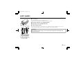
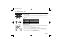
L53H2, H4/XE GB 2001, 9, 18
VCC-6592P
VCC-6594P
INSTRUCTION MANUAL
BEDIENUNGSANLEITUNG
MANUEL D’INSTRUCTIONS
COLOUR CCD camera
CCD-Farbkamera
Caméra CCD COULEUR
CCD
About this manual
A propos de ce manuel
• Before installing and using the camera, please read this manual
carefully. Be sure to keep it handy for later reference.
• Avant d’installer et d’utiliser la caméra, veuillez lire ce manuel
attentivement. Gardez-le à portée de main pour toute référence
ultérieure.
• This manual gives basic connections and operating instructions for 2
PAL models (VCC-6592P, 6594P).
• Ce manuel couvre les branchements et instructions pour l’utilisation
de base pour 2 modèles de format PAL (VCC-6592P et 6594P).
Über diese Bedienungsanleitung
• Lesen Sie bitte vor der Montage und dem Inbetriebnehmen der Kamera
zuerst diese Bedienungsanleitung sorgfältig durch und bewahren Sie
sie zum späteren Nachschlagen auf.
• In dieser Anleitung finden Sie die Anschlüsse und die Grundbedienung
für 2 PAL-Modelle (VCC-6592P und 6594P)
2
PAL
VCC-6592P, 6594P
L53H2, H4/XE GB 2001, 9, 18
1AC6P1P2424-L53H2, H4/XE (0901KPS-DSP)
Sanyo Electric Co, Ltd.
Printed in Japan
L53H2, H4/XE GB 2001, 9, 18
Depending on the conditions of use, installation and environment,
please be sure to make the appropriate settings and adjustments. If you
need help with installation and/or settings, please consult your dealer.
• Built-in interline transfer method 1/3" CCD, approx. 470,000
CONTENTS
picture elements
PRECAUTIONS........................................................................................ 2
PARTS NAMES........................................................................................ 3
CONCERNING AUTO-IRIS LENSES......................................................... 6
MOUNTING THE LENS ........................................................................... 7
CONNECTIONS ....................................................................................... 9
SETTINGS................................................................................................12
TROUBLESHOOTING..............................................................................18
SPECIFICATIONS.....................................................................................19
ACCESSORIES
2 Clamping core A: VCC-6594P...................................................2 pc.
VCC-6592P...................................................3 pc.
3 Clamping core B: VCC-6594P...................................................1 pc.
VCC-6592P...................................................2 pc.
English
2
1
• Equipped with a DSP (Digital Signal Processor) function
• Horizontal resolution, more than 520 TV lines
• High sensitivity, minimum required illumination is 0.3 lux (F1.2,
AGC HI position)
• Two types of backlight compensation functions (multi-spot
photometry and center focus photometry)
• Low smear, anti-blooming, low lag, no burning and no geometric
distortion using the CCD solid state image device.
• 100% solid state components giving excellent immunity to shock
and vibration
• Not subject to interference from magnetic or electrostatic fields
• Power supply: 24 V AC operation (VCC-6594P)
12 V DC operation (VCC-6592P)
1 Lens iris plug (4-pin)..................................................................1 pc.
1
FEATURES
3
L53H2, H4/XE GB 2001, 9, 18
PRECAUTIONS
In case of problem
Do not use the camera if smoke or a strange odour comes from the
unit, or if it seems not to function correctly. Disconnect the power
cord immediately, and consult your dealer (or a Sanyo Authorized
Service Centre).
Do not open or modify
Do not open the cabinet, as it may be dangerous and cause damage
to the unit. For internal settings and repairs, consult your dealer (or a
Sanyo Authorized Service Centre).
Do not put objects inside the unit
Make sure that no metal objects or flammable substance get inside
the camera. If used with a foreign object inside, it could cause a fire,
short-circuits or damages.
If water or a liquid gets inside the camera, disconnect the power cord
immediately, and consult your dealer (or a Sanyo Authorized Service
Centre). Be careful to protect the camera from rain, sea water, etc.
Install away from electric or magnetic fields
If installed close to a TV, radio transmitter, magnet, electric motor,
transformer, audio speakers the magnetic field they generate will
distort the image.
Protect from high temperatures
Do not install close to stoves, or other heat generating devices, such
as spotlights, etc., or where it could be subject to direct sunlight, as
that could cause deformation, discoloration or other damages.
Be careful when installing close to the ceiling, in a kitchen or boiler
room, as the temperature may raise to high levels.
Install where the temperature range will stay between –10˚C and
50˚C.
(no condensation)
Cleaning
• Dirt can be removed from the cabinet by wiping it with a soft
cloth. To remove stains, wipe with a soft cloth moistened with a
soft detergent solution and wrung dry, then wipe dry with dry
soft cloth.
• Do not use benzine, thinner or other chemical product on the
cabinet, as that may cause deformation and paint peeling.
Before using a chemical cloth, make sure to read all
accompanying instructions. Make sure that no plastic or rubber
material comes in contact with the cabinet for a long period of
time, as that may cause damage or paint peeling.
ENGLISH
Be careful when handling the unit
To prevent damages, do not drop the camera or subject it to strong
shock or vibration.
Protect from humidity and dust
To prevent damages to the camera, do not install it where there is
greasy smoke or steam, where the dampness may get too high, or
where there is a lot of dust.
2 English
L53H2, H4/XE GB 2001, 9, 18
PARTS NAMES
1 Video output connector (VIDEO OUT: BNC type)
(VCC-6592P)
Connect this connector to a device such as a VCR or monitor with a VIDEO IN connector.
3
2 Power input terminal
4
1
5
2
1
3
• VCC-6592P: 12 V DC input terminal (12 V DC, GND)
• VCC-6594P: 24 V AC input terminal (AC 24 V, AC 24 V, GND)
3 Y/C OUT connector (4 pin)
2
Separate Y (luminance) and C (chroma) signals are output from this terminal.
A better picture quality is obtained if the monitor or VCR is connected to this connector.
4
1 Y signal ground
2 C signal ground
3 Y signal: 1.0 Vp-p, 75 ohms, unbalanced, negative sync
4 C signal: 0.3 Vp-p, 75 ohms, unbalanced
4 Power indicator (POWER)
(VCC-6594P)
Comes on when the power to the camera is on.
5 External sync composite video signal input connector
4
1
2
6
English
(VBS IN: BNC type)
Connect to this connector the synchronizing signal output from a synchronizing signal device or the composite
signal of a video distributor.
6 Line phase adjustment volume (LINE PHASE) (VCC-6594P only)
When using two cameras or more, the image on the monitor may roll vertically when switching sources. This
rolling can be minimized by turning this volume.
3
L53H2, H4/XE GB 2001, 9, 18
PARTS NAMES
7 Lens mount cap
The cap is installed to protect the lens mount section.
Remove the lens mount cap before installing a lens (sold separately).
8 Flange-back adjustment screw (FLANGE BACK ADJ.)
9
7
8
F
9 Flange-back lock screw (FLANGE BACK LOCK)
F Camera installation bracket
1
2
3 2
The bracket can be fixed at the top or bottom of the camera. When fixing the bracket, be sure to use the
longer screws and install the shorter screws on the opposite side to seal the openings.
CAUTION:
When installing the camera support, select a location that can support the total weight of the
camera and accessories.
1
1 Shorter screws: M3 x 4
2 Longer screws: M3 x 6
3 Camera mounting screw
hole: 1/4"-20 UNC
4 English
L53H2, H4/XE GB 2001, 9, 18
PARTS NAMES
G Lens iris output connector (LENS)
This 4-pin connector is used to send the DC control signal and power supply to an auto-iris type lens.
H
H Camera setup section (under the cover)
G
English
5
These settings are for when using a 1/3 inch CS mount DC (without EE internal amplifier) type lens. However,
if due to installation conditions or environment the settings may need to be modified for best results (see
"SETTINGS"). To access the controls, remove the cover fixing screw, then remove the cover.
NOTE: When using a 1/2 or 2/3 inch C mount VIDEO (with EE internal amplifier) auto-iris type lens, set the
A.I. LENS switch to the VIDEO position.
L53H2, H4/XE GB 2001, 9, 18
CONCERNING AUTO-IRIS LENSES
VR301
DC
VIDEO
A. I.
LENS
DC type auto-iris lens
A lens without amplifier circuit that operates only on a DC power source. In general, this type of lens is
referred to as DC type coil lens or DC type non-amplifier lens.
(Set the A.I. LENS switch to the DC position.)
VIDEO type auto-iris lens
A lens with amplifier circuit that operates on video signal and DC power source. In general, this type of lens is
referred to as EE amplifier type lens.
ALC and LEVEL volume level controls are available on the lens for iris adjustments.
(Set the A.I. LENS switch to the VIDEO position.)
Compatible auto-iris lenses
1/3 inch Sanyo DC type lens
VCL-CS8LY: Standard angle, f= 8 mm
VCL-CS4LY: Wide angle, f= 4 mm
VCL-CS2LY: Ultra-wide angle, f= 2.8 mm
VIDEO type lens
Standard angle, f= 9 mm
Telephoto angle, f= 12 mm
Greater telephoto angle, f= 16 mm
If using a VIDEO type auto-iris lens
• Set the ALC and LEVEL controls on the lens to adjust the iris. Normally the ALC volume should be turned
all the way to Av (Average).
• Depending on the type of lens used, the lens may not perform properly. In such a case, adjust the LEVEL
volume on the lens casing to correct.
6 English
L53H2, H4/XE GB 2001, 9, 18
MOUNTING THE LENS
Please use a DC type auto-iris lens (sold separately).
1
C mount type lens
Check the lens mount
Do not use a lens if the length “L” is more than 5 mm. That may damage the
camera and prevent proper installation.
2
L
1
2
3
2
CS mount
type lens
English
7
3
Remove the lens mount cap from the camera.
Install the auto-iris lens.
CS mount type lens
Carefully align the lens mount with the camera opening, then turn the lens slowly to install it.
C mount type lens
To allow for flange-back adjustment, install the C-mount adaptor (option) on the lens mount, then carefully
align the lens mount with the camera opening and turn the lens slowly to install it.
Connect the lens plug to the lens iris output connector (LENS) on the side of the camera.
When using lenses from other makers, the plug shape may not correspond to the terminal on the camera.
In such a case, remove the original plug and using a soldering iron, connect the supplied lens iris plug
according to the diagram. (Refer to page 8.)
NOTE: When using an auto-iris lens, the supplied clamping core B must be installed on the lens wire, in
order to prevent electromagnetic interference to the other devices connected.
L53H2, H4/XE GB 2001, 9, 18
MOUNTING THE LENS
Rewiring the lens cable in the lens iris plug
1
1
2
2
Prepare the lens cable.
Cut the cable at the plug, then remove approx. 8 mm of the cable sheath and strip about 2 mm from each wire.
Install the lens iris plug.
Solder the cable to the pins following the correct pin layout (refer to the table and illustrations), then close
the plug cover.
Pin layout
2
1
3
4
2
1
4
3
1
2
3
4
DC type lenses
Brake coil (–)
Brake coil (+)
Drive coil (+)
Drive coil (–)
VIDEO type lenses
+12 V DC (50 mA max.)
Not used
Video output (1.0 Vp-p, high impedance)
Ground (for video signal and DC power)
Flange-back adjustment
If the pick-up surface is not correctly positioned with relation to the lens focal point, the picture will be out of
focus (in particular when using auto-iris power zoom lenses, sold separately). If that is the case, adjust the
flange-back position as described below.
2, 3
3
ADJ.
1
LOCK
4
1
2
3
4
Using a + screwdriver, loosen the FLANGE BACK LOCK screw (M2:+).
Set the zoom lens to the maximum telephoto position, set the focus using the focus ring on the lens.
Set the zoom lens to the maximum wide angle position, set the focus using the FLANGE BACK ADJ. screw.
Repeat steps 2 and 3, until the image stays in focus when changing from a telephoto shot to a wide angle shot.
When the setting is complete, tighten the FLANGE BACK LOCK screw.
8 English
L53H2, H4/XE GB 2001, 9, 18
CONNECTIONS
(VCC-6592P only)
1
(A)
2A (A)
2A (A)
12 V DC
+
(Video signal connections)
: VIDEO IN
: VIDEO OUT
The peripheral devices (VCR, monitor, lens, etc.) and cables are
sold separately.
Make the video signal connection between the camera and
the monitor or time lapse VCR.
2
Use a commercially available 12 V DC adaptor.
Connect an DC 12 V power source to the 12 V DC input terminal
on the back of the camera.
2A: When using this unit, the supplied clamping core (A or B) must be
installed on the power cord and BNC cable, in order to prevent
electromagnetic interference to the other devices connected.
English
9
2A (B)
12 V DC connection
Push to insert the cable
Basic connection for monitoring or recording
1
2
–
3
12 V DC input
3
Insert the plug of this power cord into a wall outlet.
The POWER indicator (A) will light. Adjust the picture on the
monitor using the Brightness and Contrast controls etc.
Coaxial cable type and maximum length
• Cable type RG-59U (3C-2V), 250 m maximum.
• Cable type RG-6U (5C-2V), 500 m maximum.
• Cable type RG-11U (7C-2V), 600 m maximum.
CAUTION:
• The RG-59U type cable should not be run through electrical
conduits or through the air.
• Using CCTV/Video-grade coaxial cable.
L53H2, H4/XE GB 2001, 9, 18
CONNECTIONS
(VCC-6592P only)
1
(A)
2A (A)
12 V DC
+
(Video signal connections)
: VIDEO IN
: VIDEO OUT
2
–
2A (B)
12 V DC connection
Push to insert the cable
Connections to the camera Y/C OUT connector
3
The peripheral devices (VCR, monitor, lens, etc.) and cables are
sold separately.
CAUTION:
1
2
Using a coaxial cable (twin type, 75 ohms), connect the Y/C
OUT connector from the camera to the S-VIDEO input
terminal on the monitor or time lapse VCR.
Use a commercially available 12 V DC adaptor.
Connect an DC 12 V power source to the 12 V DC input terminal
on the back of the camera.
2A: When using this unit, the supplied clamping core (A or B) must be
installed on the power cord and BNC cable, in order to prevent
electromagnetic interference to the other devices connected.
3
12 V DC input
The POWER indicator (A) will light. Adjust the picture on the
monitor using the Brightness and Contrast controls.
• Please use a monitor with a Y/C or S-VIDEO input terminal, or a
time lapse VCR with a S-VIDEO input terminal.
• Use a Mini-DIN (round type, 4-pin) plug to connect to the Y/C
connector.
Never use a coaxial cable longer that 10 metres to connect the
camera to the S-VIDEO input terminal.
10 English
L53H2, H4/XE GB 2001, 9, 18
CONNECTIONS
(VCC-6594P only)
1
(A)
3
2A
AC 24 V connection
Push to insert the cable
AC 24 V
2
(Video signal connections)
: VIDEO IN
: VIDEO OUT
Basic connection for monitoring or recording
The peripheral devices (VCR, monitor, lens, etc.), AC adaptor
and cables are sold separately.
1
Make the video signal connection between the camera and
the monitor or time lapse VCR.
2
Use a commercially available 24 V AC adaptor.
Connect an AC 24 V power source to the AC 24 V input terminal
on the back of the camera.
2A: When using this unit, the supplied clamping core (A) must be
installed on the power cord and BNC cable, in order to prevent
electromagnetic interference to the other devices connected.
English
11
2A
~ ~ GND
3
Insert the plug of this power cord into a wall outlet.
The POWER indicator (A) will light. Adjust the picture on the
monitor using the Brightness and Contrast controls etc.
Coaxial cable type and maximum length
• Cable type RG-59U (3C-2V), 250 m maximum.
• Cable type RG-6U (5C-2V), 500 m maximum.
• Cable type RG-11U (7C-2V), 600 m maximum.
CAUTION:
• The RG-59U type cable should not be run through electrical
conduits or through the air.
• Using CCTV/Video-grade coaxial cable.
L53H2, H4/XE GB 2001, 9, 18
SETTINGS
(VCC-6592P only)
The illustration shows the factory default settings for the switches in the camera setup section.
The camera settings are described on the assumption that a DC type auto iris lens is being used. If you are using a VIDEO type auto iris lens, be
sure to read the Note which is given.
6
7-a
9
1
R
B
VR302
VR301
VR303
2
3
ON
1
2
3
4
5
6
7
8
DC
VIDEO
9 10
A. I.
LENS
4
5
1 2345678
6
ES/EI
1
MSB
2
GAIN APER
3
LSB
HI
SHRP
NORM NORM
BLC
WB
MULT CENT MANU
OFF
OFF
ATW
SC-PHASE 1
180
0
90
Control name
High speed electronic shutter (ES)/
Electronic iris (EI) setting
Auto gain control setting (HI/NORM)
Aperture compensation setting
(SHRP/NORM)
Backlight compensation setting (BLC)
(MULT/OFF)
Backlight compensation setting (BLC)
(CENT/OFF)
White balance switch (MANU/ATW) and
colour (R or B) adjustment volume
External sync setting (SC-PHASE1)
7
7-a External sync horizontal adjustment (H)
8 Auto-iris lens setting (A.I. LENS), see page 6
9 Lens iris level adjustment volume
Position
1/50 sec.
HI
SHRP
OFF
OFF
ATW
0
adjustable
DC
adjustable
0
* The sticker on the inside of cover.
12 English
L53H2, H4/XE GB 2001, 9, 18
SETTINGS
(VCC-6594P only)
The illustration shows the factory default settings for the switches in the camera setup section.
The camera settings are described on the assumption that a DC type auto iris lens is being used. If you are using a VIDEO type auto iris lens, be
sure to read the Note which is given.
6
R
9
B
VR302
Control name
1 High speed electronic shutter (ES)/
Electronic iris (EI) setting
VR301
VR303
ON
1
2 Auto gain control setting (HI/NORM)
2
3
4
5
6
7
8
DC
VIDEO
9 10
3 Aperture compensation setting
Position
1/50 sec.
HI
SHRP
(SHRP/NORM)
A. I.
LENS
4 Backlight compensation setting (BLC)
OFF
(MULT/OFF)
1 2345678
5 Backlight compensation setting (BLC)
OFF
(CENT/OFF)
6 White balance switch (MANU/ATW) and
ES/EI
1
2
GAIN APER
3
HI
SHRP
BLC
WB
MULT CENT MANU
SYNC
LL
NC
7 Syncronisation (SYNC) setting (INT/LL)
8 Auto-iris lens setting (A.I. LENS), see page 6
9 Lens iris level adjustment volume
MSB
LSB
NORM NORM
OFF
* The sticker on the inside of cover.
English
13
OFF
ATW
INT
ATW
colour (R or B) adjustment volume
INT
DC
adjustable
L53H2, H4/XE GB 2001, 9, 18
SETTINGS
Electronic shutter settings and electronic iris
settings
When all of these switches are down, electronic shutter (1/50 sec or
auto iris setting) is enabled. The electronic shutter can be set to one
of 7 speeds as shown in Table A.
Furthermore, when all switches are up, electronic iris setting is
enabled.
Notes on the electronic shutter:
• Using the high speed electronic shutter indoors with low lighting,
•
•
•
•
will give darker pictures. In such a case, add some lights to make
sure the lighting is sufficient. If the lighting is very bright, pay
attention to the light angle in order to avoid or minimize the
smear phenomenon effect.
Use a manual or fixed iris lens and set the lens aperture to the
shortest F stop. Set the switch (1 – 3) to the up position.
The electronic iris is suitable for normal indoor use. When the
switch (1 – 3) is set to the up position, do not use an auto-iris lens.
If used under fluorescent light, the image may flicker. In such a
case, change to incandescent lighting or set the switch (1 – 3) to
the down position and use an auto-iris lens.
If conditions are outside the electronic iris operation range or
more than the maximum illumination, it will cause saturation of
the CCD. In that case, use a manual iris lens.
Table A (switch 1 ~ 3)
1
2
3
4
5
6
7
8
1/50(AI) 1/120 1/500 1/1000 1/2000 1/4000 1/10000 EI
1
2
3
1
2
3
1
2
3
1
2
3
1
2
3
1
2
3
1
2
3
1
2
3
(Unit: sec.)
Automatic Gain Control (AGC) setting
The automatic gain control can be turned HI or NORM
using the AGC switch 4 in the camera setup section.
HI: Auto gain control fuction on (+6 dB)
NORM: Auto gain control (normal gain)
4
Note: In the AGC switch position HI, noise may be noticed in dark
places of dimly lit objects. In the AGC switch position NORM,
the noise will be reduced, but the sensitivity will also be
reduced to half in this case.
Aperture
The initial setting for switch 5 is up (SHRP) so that the
contours of the object are emphasized. However, if the
contours of the object are already emphasized more
than required, set switch 5 to the down (NOR) position.
5
14 English
L53H2, H4/XE GB 2001, 9, 18
SETTINGS
Backlight compensation setting
This camera has two different backlight
compensation functions: Normally backlight
compensation switch 6 (MULT) and 7 (CENT)
are set to the down (OFF) position. Change
6
7
the backlight compensation switch settings
depending on the conditions.
• MULT mode: Use this position when applying backlight
compensation to the whole of the screen.
• CENT mode: Use this position when applying backlight
compensation to only the central portion of the
screen.
Note:
• If switches 6 and 7 are set to the up (ON) position at the same
time, the MULT setting will have priority.
• When MULT mode is set, scenes with no backlighting may appear
extremely dark and the object may appear over-exposed. If this
happens, set to CENT mode.
English
15
(MULTI mode: 64 sections)
(CENT mode)
If using a VIDEO type auto-iris lens
• The ALC volume on the lens should be turned all the way to Av
(Average).
• If the backlight compensation function does not compensate
properly for the conditions, set using the LEVEL volume on the
lens.
L53H2, H4/XE GB 2001, 9, 18
SETTINGS
White balance adjustment
R
8
B
VR302
VR303
1
2
Connect the VBS signal output for the other camera to the VBS
IN connector at the rear of this camera.
If the signals are not synchronized, change the sub-carrier (SC-P1)
switches as follows.
Setting
Default
Set to 90˚ counterclockwise
Set to 180˚ counterclockwise
Set to 270˚ counterclockwise
VR304
Normally the switch 8 (WB) is set to the down (ATW: auto white
balance) position and the white balance is adjusted automatically. If a
manual white balance adjustment is necessary, follow the steps below.
Set the switch 8 (WB) to the up (M: manual) position, then adjust the
colour.
• Turn RED (VR302) to set the red ratio and/or BLUE (VR303) to set
the blue ratio.
External sync adjustment (VBS) (VCC-6592P only)
H-P
Synchronization settings
The default setting is internal synchronization (INT). You can
change the power supply synchronization by moving switch 9
to the up (LL) position. Refer to “Line phase adjustment”
for details.
9
9-pin
OFF (down)
OFF
ON
ON
10-pin
OFF
ON (up)
OFF
ON
10
Note:
• The sub-carrier switches let you make broad adjustments to the
sub-carrier phase. If finer adjustments are required, contact the
place of purchase.
• The type and length of the cable which is connected to the VBS
connector may cause the horizontal synchronization being out of
phase. If this happens, adjust VR304 (H-P: horizontal sync).
16 English
L53H2, H4/XE GB 2001, 9, 18
SETTINGS
Lens iris adjustment
If using a DC type auto-iris lens, you will need to set the LEVEL
(VR301) volume when shooting in the conditions described below.
VR301
L (counterclockwise): To decrease the contrast
H (clockwise): To increase the contrast
• If shooting simultaneously in a dark room and through a bright
window.
• If the subject background is extremely bright or dark.
• If the brightness of the picture on the monitor is not correct.
Line phase adjustment (VCC-6594P only)
When using a camera switcher to connect 2 cameras or more to one
monitor, there may be a vertical roll of the images when switched. In
such a case, set as described below.
1
2
Set the switch 9 (SYNC) to the up (LL) position.
Switch the display on the monitor from camera 1 to camera 2.
Adjust the LINE PHASE volume on camera 2 until the vertical roll
of the image stops.
If more than two cameras are used, please repeat this procedure
for all the cameras.
9
CAUTION:
If the vertical roll cannot be corrected by setting the LINE PHASE
volume on camera 2, try setting the LINE PHASE volume on camera
1. If it still cannot be corrected, please check that the polarity of the
power cords of all connected devices is correct.
English
17
L53H2, H4/XE GB 2001, 9, 18
TROUBLESHOOTING
Before taking the camera for repairs, please check below to make sure that the camera is used correctly. If it still does not perform correctly, please
consult your dealer or a Sanyo Authorized Service Centre.
No picture on the monitor screen
Is the power turned on to all connected devices? Is the voltage correct?
Are all the signal connecting cables correctly connected?
Is the lighting sufficient?
Has the lens cap been removed?
Is the lens type (DC or VIDEO) correctly selected?
Depending on the type of lens, the A. I. LENS switch must be set accordingly.
• Is the iris control correctly set?
•
•
•
•
•
•
•
•
•
The picture is not clear
Is the monitor correctly adjusted?
Is the flange-back position correctly set?
Is the lens focus correctly adjusted?
Are the lens surfaces clean?
If there is dust or finger prints on the lens, the image quality will deteriorate. To clean the lens use a soft cloth or a commercially available lens
cleaning set.
SERVICE
This camera is a precision instruments and if treated with care, will provide years of satisfactory performance. However, in the event of a problem,
the owner is advised not to attempt to make repairs or open the cabinet. Servicing should always be referred to your dealer or Sanyo Authorized
Service Centre.
18 English
L53H2, H4/XE GB 2001, 9, 18
SPECIFICATIONS
Camera:
Scanning system
: PAL standard
(625 TV lines, 25 frames/sec.)
PLL 2:1 interlace
1/3 inch solid state image device CCD
795 (H) x 596 (V)
752 (H) x 582 (V)
Internal sync, External sync automatic
switchable (VCC-6592P only)
Internal sync, Line lock manually switchable
(VCC-6594P only)
520 TV lines horizontally, 400 TV lines
vertically
1.0 Vp-p/75 ohms, composite
Y: Video; 0.7 Vp-p + sync; 0.3 Vp-p/75 ohms
C: Burst; 0.3 Vp-p/75 ohms (VCC-6592P only)
More than 48 dB
Approx. 0.3 lux with a F 1.2 lens (AGC, HI)
Approx. 0.6 lux with a F 1.2 lens (AGC, NORM)
Interlace
Image device
Picture elements
Effective picture elements
Synchronizing system
:
:
:
:
:
Resolution
:
Video output level
Y/C signal outputs
:
:
Video S/N ratio
Minimum required
illumination
(incandescent lighting)
Backlight compensation
:
:
Iris function
: AI/EI selectable by switches (Electronic
Electronic iris range
Electronic shutter
: 0.6 lux to 50,000 lux (F 1.2 lens)
: 7 speeds, selectable by switches:
: Manual MULT/CENT/OFF switching (Active
when using an auto-iris lens)
shutter)
Flange-back
White balance
Lens mount
AGC
English
19
:
:
:
:
(1/50, 1/120, 1/500, 1/1000, 1/2000,
1/4000, 1/10000 sec.)
12.5 mm ± 0.5 mm
ATW/Manual switching
CS mount
HI/NORM
Environmental conditions : Temperature: –10˚C ~ +50˚C
Humidity: less than 90% (no condensation)
Power supply
: 12 – 15 V DC (VCC-6592P)
24 V AC, 50 Hz (VCC-6594P)
Power consumption
: VCC-6592P: Approx. 2.7 W
(with auto iris lens)
Approx. 2.0 W
(without auto iris lens)
VCC-6594P: Approx. 2.8 W
(with auto iris lens)
Approx. 2.1 W
(without auto iris lens)
Weight
: Approx. 310 g (without lens)
L53H2, H4/XE GB 2001, 9, 18
SPECIFICATIONS
Dimensions
56
109
100
0.5
45
56
45
11
12.6
22.4
1/4”–20 UNC
28
(VCC-6592P)
28
(VCC-6594P)
Features and specifications are subject to change without prior notice or obligations.
20 English