1
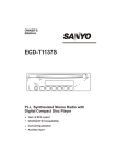
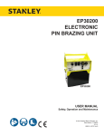
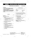
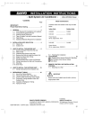
INSTALLATION INSTRUCTIONS
— Split System Air Conditioner —
CONTENTS
IMPORTANT
Please Read Before Starting
Model Combinations
Page
Combine indoor and outdoor units only as listed below.
Indoor units
XS1852 (PNR-XS2432)
1. GENERAL ............................................................. 3
1-1. Tools Required for Installation (not supplied)
1-2. Accessories Supplied with Unit
1-3. Optional Copper Tubing Kit
1-4. Type of Copper Tube and Insulation Material
1-5. Additional Materials Required for Installation
1-6. Operating Range
1-7. Tubing Length
Power Supply :
60Hz, single-phase, 208/230 V
Units should be installed by licensed contractor
according to local code requirements
2. SELECTING THE INSTALLATION SITE ............ 5
Indoor Unit
Outdoor Unit
2-1. Baffle Plates for the Outdoor Unit
7. HOW TO PROCESS TUBING ........................... 21
7-1. Use of the Flaring Method
7-2. Flaring Procedure with a Flare Tool
7-3. Precaution before Connecting Tubes Tightly
7-4. Precautions during Brazing
7-5. Connecting Tubing between Indoor and
Outdoor Units
7-6. Insulating the Refrigerant Tubing
7-7. Taping the Tubes
7-8. Finishing the Installation
3. HOW TO INSTALL THE INDOOR UNIT .............. 7
3-1.
3-2.
3-3.
3-4.
3-5.
Outdoor units
C1852, CL1852
Suspending the Indoor Unit
Preparation for Suspending
Placing the Unit Inside the Ceiling
Installing the Drain Piping
Checking the Drainage
8. AIR PURGING .................................................... 24
■ Air Purging with a Vacuum Pump
(for Test Run)
■ Ceiling Panel ...................................................... 11
3-6. Before Installing the Ceiling Panel
3-7. Installing the Ceiling Panel
3-8. When Removing the Ceiling Panel for
Servicing
3-9. Duct for Fresh Air
9. TEST RUN .......................................................... 26
9-1. Performing Test Run
9-2. Performing Test Run with Optional Wired
Remote Control Unit
9-3. Basic Function of the Service Valves
9-4. Pump Down
4. HOW TO INSTALL THE REMOTE
CONTROL UNIT ................................................. 15
■ Wireless Remote Control Unit
4-1. Mounting on a Wall
■ Wired Remote Control Unit (Option)
4-2. Installing the Wired Remote Control Unit
5. ADDRESS SWITCHES ....................................... 17
5-1. Finding the Address Switches
5-2. Switch Positions for 2 Units or 2 Groups of
Units
6. ELECTRICAL WIRING ....................................... 18
6-1. General Precautions on Wiring
6-2. Recommended Wire Length and Wire
Diameter for Power Supply System
6-3. Wiring Instructions for the Outdoor Unit
6-4. Examples of Incorrect Wiring
6-5. How to Connect Wiring to the Terminal
85464359128000
SANYO
2000
1
S4359128
SANYO FISHER COMPANY
A DIVISION OF SANYO NORTH
AMERICA CORPORATION
21605 Plummer Street
Chatsworth, CA91311
Important
IMPORTANT!
Please Read Before Starting
When
Transporting
……………………………………………………………………
Be careful when picking up and moving the indoor and
outdoor units. Get a partner to help, and bend your knees
when lifting to reduce strain on your back. Sharp edges or
thin aluminum fins on the air conditioner can cut your
fingers.
This air conditioning system meets strict safety and
operating standards. As the installer or service person, it
is an important part of your job to install or service the
system so it operates safely and efficiently.
For safe installation and trouble-free operation,you
must:
When
Installing
……………………………………………………………………
ⓦ Carefully read this instruction booklet before beginning.
…In a Room
Properly insulate any tubing run inside a room to prevent
“sweating” that can cause dripping and water damage to
walls and floors.
ⓦ Follow each installation or repair step exactly as shown.
ⓦ Observe all local, state, and national electrical codes.
ⓦ Pay close attention to all warning and caution notices
given in this manual.
…In Moist or Uneven Locations
Use a raised concrete pad or concrete blocks to provide a
solid, level foundation for the outdoor unit. This prevents
water damage and abnormal vibration.
This symbol refers to a hazard
or unsafe practice which can
result in severe personal injury
or death.
CAUTION
…In an area with High Winds
Securely anchor the outdoor unit down with bolts and a
metal frame. Provide a suitable air baffle.
This symbol refers to a hazard
or unsafe practice which can
result in personal injury or
product or property damage.
…In a Snowy Area
(for Heat Pump-type Systems)
If Necessary, Get Help
Install the outdoor unit on a raised platform that is higher
than drifting snow. Provide snow vents.
These instructions are all you need for most installation
sites and maintenance conditions. If you require help for a
special problem, contact our sales/service outlet or your
certified dealer for additional instructions.
When
Connecting Refrigerant Tubing
……………………………………………………………………
• Execute enough ventilation in case refrigerant gases
leak during operations. Be careful that the contact of the
refrigerant gases with the flare will cause the generation
of poisonous gases.
In Case of Improper Installation
The manufacturer shall in no way be responsible for
improper installation or maintenance service, including
failure to follow the instructions in this document.
• Keep all tubing runs as short as possible.
SPECIAL PRECAUTIONS
• Use the flare method for connecting tubing.
When
Wiring
……………………………………………………………………
• Apply refrigerant lubricant to the matching surfaces of
the flare and union tubes before connecting them, then
tighten the nut with a torque wrench for a leak-free
connection.
ELECTRICAL SHOCK CAN CAUSE
SEVERE PERSONAL INJURY OR DEATH.
ONLY A QUALIFIED, EXPERIENCED
ELECTRICIAN SHOULD ATTEMPT TO
WIRE THIS SYSTEM.
• Check carefully for leaks before starting the test run.
NOTE
• Do not supply power to the unit until all wiring and
tubing are completed or reconnected and checked.
Depending on the system type, liquid and gas lines may
be either narrow or wide. Therefore, to avoid confusion the
refrigerant tubing for your particular model is specified as
either “narrow” or “wide” rather than as “liquid” or “gas”.
• Highly dangerous electrical voltages are used in this
system. Carefully refer to the wiring diagram and these
instructions when wiring. Improper connections and
inadequate grounding can cause accidental injury or
death.
When
Servicing
……………………………………………………………………
• Turn the power OFF at the main power box (mains)
before opening the unit to check or repair electrical
parts and wiring.
• Ground the unit following local electrical codes.
• Connect all wiring tightly. Loose wiring may cause
overheating at connection points and a possible fire
hazard.
• Keep your fingers and clothing away from any moving
parts.
• Clean up the site after you finish, remembering to check
that no metal scraps or bits of wiring have been left
inside the unit being serviced.
2
S4359128
1. General
Part Name
This booklet briefly outlines where and how to install
the air conditioning system. Please read over the
entire set of instructions for the indoor and outdoor
units and make sure all accessory parts listed are with
the system before beginning.
Figure
Wireless
remote control unit
AAA alkaline
battery
1
2
Special
screw
4 ✕ 16 mm
Tapping screw
1-1. Tools Required for Installation (not supplied)
1. Standard screwdriver
2. Phillips head screwdriver
3. Knife or wire stripper
4. Tape measure
5. Level
6. Sabre saw or key hole saw
7. Hacksaw
8. Core bits
9. Hammer
10. Drill
11. Tube cutter
12. Tube flaring tool
13. Torque wrench
14. Adjustable wrench
15. Reamer (for deburring)
16. Service valve wrench
17. Wire cutter
Tapping screw
Q’ty
1
1
For wide tubes
Installation
gauge
1
For adjusting the
unit position
Insulating
tape
1
For wide tube
flare nuts
Hose band
2
For securing drain
hose
Packing
1
For drain joint
Drain
insulator
1
For drain joint
Drain hose
1
Drain hose
adapter
1
(White for insulating)
Owner’s
manual
Hexagonal
Wrench*
1
1-4. Type of Copper Tube and Insulation Material
If you wish to purchase these materials separately
from a local source, you will need:
1.
Deoxidized annealed copper tube for refrigerant
tubing.
Cut each tube 12 in. to 16 in. longer than the
appropriate lengths to dampen vibration between
units.
2.
Foamed polyethylene insulation for 5/8"
(15.88 mm) O.D. copper tubes as required to
precise length of tubing. Wall thickness of the
insulation should be not less than 0.3 inch
(8 mm).
Remarks
For determining
suspension bolt
pitch
Flare
insulator
TOTA 4 ✕ 16
Copper tubing for connecting the outdoor unit to the
indoor unit is available in kits which contain the narrow
and wide tubing, fittings and insulation. Consult your
nearest sales outlet or A/C workshop.
Table 1-1
Figure
1
1-3. Optional Copper Tubing Kit
1-2. Accessories Supplied with Unit
Part Name
Full-scale
installation
diagram
Q’ty
Check local electrical codes
and regulations before
obtaining wire. Also, check
any specified instructions or
limitations.
CAUTION
1-5. Additional Materials Required for Installation
1.
2.
3.
4.
5.
Insulated staples or clamps for connecting wire
(See your local codes.)
Putty
Refrigeration tubing lubricant
Clamps or saddles to secure refrigerant tubing
Scale for weighing
1-6. Operating Range
For drain outlet
Temperature Indoor Air Intake
Cooling
1
1
Maximum
95°F DB, 71°F WB
Minimum
67°F DB, 57°F WB
Outdoor Air Intake
115°F DB
67°F DB (0°F DB)*
*CL&&&& Models
To open and shut
the Narrow Tube
Service Valve
*Packed in the outdoor unit
3
S4359128
1-7. Tubing Length
● Refrigerant tubing between the indoor and outdoor
units should be kept as short as possible.
Tubing length (L)
INDOOR
UNIT
● Select and decide the installation location so that
the length of the refrigerant tubing will be within the
limits given in Table 1-2.
Elevation difference (H)
OUTDOOR
UNIT
0711_M_I
Fig. 1-1
Table 1-2
Models
C1852
CL1852
Tubing Data
Tubing size
outer dia.
Narrow tube
in. (mm)
1/4 (6.35) : Thickness 0.0314" (0.8 mm)
Wide tube
in. (mm)
5/8 (15.88) : Thickness 0.0394" (1.0 mm)
Limit of tubing length
Limit of elevation
difference between
the 2 units
than indoor unit
(ft.)
65
Outdoor unit is higher
than indoor unit
(ft.)
23
Outdoor unit is lower
(ft.)
23
Max. allowable tubing length at shipment (ft.)
Required additional refrigerant *1
33
(oz./ft.)
0.27
No additional charge of compressor oil is necessary.
*1 If total tubing length becomes 33 to 65 ft., charge additional refrigerant (R22) by 0.27 oz./ft..
4
S4359128
2. Selecting the Installation Site
Indoor Unit
AVOID:
● areas where leakage of flammable gas may be
expected.
● places where large amount of oil mist exist.
● direct sunlight.
● locations near heat sources which may affect
performance of the unit.
● locations where external air may enter the room
directly. This may cause “sweating” on the air
discharge ports, causing them to spray or drip.
● locations where the remote control unit will be
splashed with water or affected by dampness or
humidity.
● installing the remote control unit behind curtains or
furniture.
● locations where the receiver in the indoor unit is
exposed to the inverter lamp light. Faulty operation
of the unit occurs.
DO:
3 ft.
● select an appropriate position from which every
corner of the room can be uniformly cooled.
● select a location where the ceiling is strong enough
to support the weight of the unit.
3 ft.
3 ft.
3 ft.
3 ft.
● select a location where tubing and drain pipe have
the shortest run to the outdoor unit.
1330_X_S
● allow room for operation and maintenance as well
as unrestricted air flow around the unit. (Fig. 2-1)
Fig. 2-1
● install the unit within the maximum elevation
difference above or below the outdoor unit and
within a total tubing length from the outdoor unit as
detailed in Table 1-2.
● allow room for mounting the remote control unit
about 3 ft. off the floor, in an area that is not in
direct sunlight nor in the flow of cool air from the
indoor unit.
NOTE
Air delivery will be degraded if the distance from the
floor to the ceiling is greater than 10 ft..
5
S4359128
Outdoor Unit
NO
Exhaust fan
Hot air
AVOID:
Heat source
● heat sources, exhaust fans, etc. (Fig. 2-2)
Outdoor
unit
● damp, humid or uneven locations.
DO:
1817_C_I
● choose a place as cool as possible.
Fig. 2-2
● choose a place that is well ventilated.
Obstacle above
CAUTION
Min. 6" (15 cm)
● Do not place objects on or sit
on the outdoor unit. Also, never
block the air intake/outlet or
exhaust. Distortion of the
outdoor unit or incomplete
combustion may result.
Min. 6" Air discharge
(15 cm)
Valve side
Min. 10"
(25 cm)
Obstacle
Air intake
● Install the outdoor unit above
snowfall line.
Min. Min.
7 ft.
7 ft.
(2 m) (2 m)
Air discharge
● allow enough room around the unit for air intake/
exhaust and possible maintenance. (Fig. 2-3)
Min. 12"
(30 cm)
1818_M_I
Ground
Min. 6 in.
(15 cm)
Air intake
● Do not introduce foreign matter
into the air intake/outlet or
exhaust. Do not poke them with
such objects as a stick.
1819_M_I
Fig. 2-3
Anchor bolts
(4 pcs)
● provide a solid base (level concrete pad, concrete
block, 4 in. × 16 in. (10 × 40 cm) beams or equal), a
minimum of 4 in. (10 cm) above ground level to
reduce humidity and protect the unit against possible
water damage and decreased service life (Fig. 2-4).
Min. 4"
(10 cm)
Air intake
Concrete
or equal
● use lug bolts or equal to bolt down unit, reducing
vibration and noise.
Ab
ou
t1
2-1. Baffle Plates for the Outdoor Unit
(CL×× models only)
6"
Abou
(40
t 4" (
10 c
m)
cm
)
1820_M_I
Fig. 2-4
When the outdoor unit is installed in a position exposed
to strong wind (like seasonal winds with low air
temperature in winter), baffle plates must be installed on
the outdoor unit. (Fig. 2-5)
6" min
Baffle
plate
Baffle
plate
Air discharge
This unit is designed so that the fan of the outdoor unit
runs at low speed when the air conditioner is operated at
low outdoor air temperatures. When the outdoor unit is
exposed to strong wind, the system pressure drops
because of the freeze protector.
6
6" min
Air discharge
NOTE
It is recommended to use baffle plates for model
CL1852. The baffle plates are not normally required for
the other models.
1821_M_I
Fig. 2-5
S4359128
3. How to Install the Indoor Unit
3-1. Suspending the Indoor Unit
This unit uses a drain pump. Use a carpenter’s level to
check that the unit is level.
3-2. Preparation for Suspending
(1)
Fix the suspension bolts securely in the ceiling
using the method shown in the diagrams (Figs.
3-1 and 3-2), by attaching them to the ceiling
support structure, or by any other method that
ensures that the unit will be securely and safely
suspended.
(2)
Follow Fig. 3-2 and Table 3-1 to make the holes
in the ceiling.
Hole-in-anchor
Hole-in-plug
Concrete
Insert
Suspension bolt (M10 or 3/8")
(field supply)
0038_T_I
Fig. 3-1
A
1/2"
(3)
820 (ceiling opening dimension)
XS1852 (PNR-XS2432) 32-9/32 (820) 28-3/4 (730)
B (suspension bolt pitch)
1/2"
1/2"
Length
Refrigerant
tubing side
Drain hose
side
1/2"
Type
A (ceiling opening dimension)
Unit : inch (mm)
B
590 (suspension bolt pitch)
Table 3-1
Determine the pitch of the suspension bolts using
the supplied full-scale installation diagram. The
diagram and table (Fig. 3-3 and Table 3-2) show
the relationship between the positions of the
suspension fitting, the unit, and the panel.
Unit: inch
Fig. 3-2
0962_S_I
Refrigerant tubing joint (narrow tube side)
Refrigerant tubing joint (wide tube side)
Drain inspection port
E
A
B
C
D
Suspension lug
15/32"
15/32"
Power supply inlet
Fig. 3-3
Table 3-2
Type
Length
A
XS1852 (PNR-XS2432) 5-29/32
B
7-7/8
C
D
Unit : inch
E
10-1/32 11-23/32 4-29/32
7
S4359128
1019_X_I
3-3. Placing the Unit Inside the Ceiling
(2)
(3)
When placing the unit inside the ceiling, determine the pitch of the suspension bolts using the
supplied full-scale installation diagram. (Fig. 3-4)
The size of the opening for the indoor unit can be
confirmed by attaching the full-scale installation
diagram beneath the unit. (Fig. 3-4)
Tubing and wiring must be laid inside the ceiling
when suspending the unit. If the ceiling is already
constructed, lay the tubing and wiring into position for connection to the unit before placing the
unit inside the ceiling.
More than 2-3/8 inch
Full-scale installation diagram
(printed on a cardboard packing)
1-7/8 inch
(1)
Full-scale installation
diagram
0963_X_I
Fig. 3-4
The length of suspension bolt must be appropriate for a distance between the bottom of the bolt
and the bottom of the ceiling of more than
2-3/8 in. as shown in Fig. 3-4.
Suspension bolt
Suspension lug
Nuts and washers
(2 sets)
Thread the 2 hexagonal nuts and washers (field
supply) onto the 4 suspension bolts as shown in
Fig. 3-5.
Upper
Lower
Use 2 sets of nuts and washers (upper and
lower), so that the unit will not fall off the suspension lugs.
(4)
Remove the protective cardboard used to protect
the fan parts during transport.
(5)
Adjust the distance between the unit and surface
of the ceiling (1-7/8 in.) using the supplied installation gauge. (Fig. 3-4)
0041_X_I
Fig. 3-5
8
S4359128
3-4. Installing the Drain Piping
(1)
Transparent part for
checking drainage
Prepare standard hard PVC pipe (O.D. 1-3/64 in.)
for the drain and use the supplied drain hose and
hose band to prevent water leaks.
The PVC pipe must be purchased separately.
The transparent part allows you to check drainage. (Fig. 3-6)
CAUTION
(2)
Packing
(supplied)
Tighten the hose clamps
so their locking nuts face
upward. (Fig. 3-6)
Drain hose
(supplied)
Hard PVC pipe
(not supplied)
Drain hose
adapter
(supplied)
0964_X_I
Fig. 3-6
Drain insulator (supplied)
After checking the drainage, wrap the supplied
packing and drain pipe insulator around the pipe.
(Fig. 3-7)
NOTE
Ensure the drain pipe has a downward gradient
(1/100 or more) and that there are no water traps.
Fig. 3-7
● Do not install an air
CAUTION
Hose band
(supplied)
0197_X_I
Air bleeder
bleeder tubes, as this
may cause water to spray
from the drain tube outlet.
(Fig. 3-8)
0047_X_I
● If it is necessary to increase the height
Fig. 3-8
of the drain pipe, the section directly
after the connection port can be raised
a maximum of 10 in. Do not raise it any
higher than 10 in., as this could result
in water leaks.
(Fig. 3-9)
5 in. or less (as short as possible)
10 in. or less
● Do not install the pipe with an upward
gradient from the connection port. It
will cause the drain water to flow
backwards and leak when the unit is
stopped. (Fig. 3-10)
0965_X_I
Fig. 3-9
Upward gradient
● Do not apply force to the piping on the
unit side when connecting the drain
pipe. The pipe should not be allowed
to hang unsupported from its connection to the unit. Fasten the pipe to a
wall, frame, or other support as close
to the unit as possible. (Fig. 3-11)
0049_X_I
Fig. 3-10
● Provide insulation for any drain pipes
that are installed indoors.
Support
pieces
0050_X_I
Fig. 3-11
9
S4359128
3-5. Checking the Drainage
After wiring and piping are completed, use the following procedure to check that the water will drain
smoothly. For this, prepare a bucket and wiping cloth
ready to catch and wipe up spilled water.
Do not supply power to the
unit until the tubing and
wiring to the outdoor unit
are completed.
(1)
Take off the tube cover and through the opening,
slowly pour about 43 oz. of water into the drain
pan to check drainage.
(2)
Do Test Run to check the drainage after completing installation. When performing Test Run, be
sure to observe the Test Run procedure.
Refer to page 37.
CAUTION
(3)
Be careful since the fan will
start turning when checking
the drainage.
5/16"(4 × 8 mm)
tapping screw
After drain checking is finished, return the
Operation Selector switch to the RUN position
(ON position ) and remount the tube cover.
CAUTION
To mount the tube cover,
use 5/16" (4 × 8 mm) tapping
screws. Do not use long
screws as they may puncture the drain pan and cause
water leakage.
Tube cover
Siphon
0966_X_I
Fig. 3-12
10
S4359128
■
Ceiling Panel
CAUTION
Never touch or attempt to
move the air direction louver
by hand or you may damage
the unit. Instead, use the
remote control unit if you
want to change the direction
or air flow.
3-6. Before Installing the Ceiling Panel
(1)
(2)
Remove the air-intake grille and air filter from the
ceiling panel. (Figs. 3-13 and 3-14)
(a)
Remove the 2 screws on the latch of the airintake grille. (Fig. 3-13)
(b)
Press on the 2 latches of the air-intake grille
with your thumb in the direction of the arrow
to open the grille. (Fig. 3-13)
(c)
With the air-intake grille open about 45˚,
remove the safety string (hook on the grille
side). (Fig. 3-14)
(d)
Pull the air-intake grille towards you to
remove it from the ceiling panel.
Latch
Screw
Air intake grille
Pull down the two panel catches on the body of
the indoor unit body. (Fig. 3-15)
Ceiling panel
0149_X_I
Fig. 3-13
Air filter
45°
Safety string
Fig. 3-14
0150_X_I
11
S4359128
3-7. Installing the Ceiling Panel
(1)
Lift the ceiling panel and position it to align the
panel hook with the panel catch of the indoor unit.
(5)
Install the air filter and air-intake grille by performing the steps in section 3-6 in reverse.
NOTE
The ceiling panel must be mounted in the correct
direction. Note that the 2 catches of the panel differ in
size.
Confirm that the catches are correctly matched between the ceiling panel and the indoor unit body.
NOTE
Rehook the safety string before closing the air-intake
grille.
(2)
Next, check to see that the ceiling panel is properly aligned with the seamline of the ceiling. If it is
not, remove the ceiling panel and slightly readjust
the indoor unit body to the proper suspension
point.
When removing the ceiling panel for servicing, remove
the air-intake grille and air filter, disconnect the wiring
connector inside the electrical component box, and
then remove the 4 mounting screws.
(3)
When the ceiling panel has been properly
aligned, use the supplied 4 mounting screws (M5)
with washers to permanently fasten the ceiling
panel.
(4)
Install the wiring connector from the ceiling panel
to the connector in the electrical component box
of the indoor unit. After installing the connector,
use the clamp on the body of the indoor unit to
secure the wiring.
3-8. When Removing the Ceiling Panel for
Servicing
Panel catch
(pull down)
Connector on unit
(inside electrical component box)
Electrical component box
Ceiling panel
Connector of ceiling panel
Unit body
Electrical
component box
Panel catch (pull down)
Clamp
Ceiling panel wiring
connector
Ceiling panel
Screws M5 with washer
Mark
Air filter
Air-intake grille
Fig. 3-15
12
S4359128
0967_X_I
3-9. Duct for Fresh Air
● Air-intake chamber (including Duct connection box and flange) are attached to the indoor unit when used to
take fresh outdoor air.
High-performance filter or Super long-life filter can be also installed in the air-intake chamber.
(1) SETUP PRIOR TO INSTALLATION
● When installing the high performance filter or super long-life filter, the parts and parts numbers of filters to be
assembled with the air-intake chamber are listed below. Please check that the correct part numbers are
present.
Air-intake
chamber
CMB-GSJ80T
(XS1852)
High performance
filter
AFT-MSJ80T
AFT-HSJ80T
Super long-life
filter
AFT-LSJ80T
(2) ACCESSORIES
● Check that the following parts are in the box when unpacking.
QT’Y
REMARKS
Cord with socket
(9P)
NAME
1
Connecting line. Connect only when
high-performance filter is used
Screw
(M5 × L125)
4
Air-intake filter
(for fastening)
Screw
(M4 × L12)
4+4
Duct connection flange/ box
(for fastening)
Duct connection box
1
(for fresh air)
Duct connection flange
1
(for connecting fresh air duct)
(3) INSTALLATION
(a) Setup for the indoor unit
● When assembling the high-performance filter, open the lid of the electrical component box, remove the socket
(9P) of the fan motor cable inside the electrical component box and connect the accessory cord with socket (9P).
CAUTION
Do not connect the “accessory cord with socket” to
the electrical component box
when the unit is used to take
fresh air.
Do not connect the “accessory cord with socket” when
assembling the super longlife filter.
Always store the “accessory
cord with socket” inside the
electrical component box.
Cord with socket
(9P)
Installation steps (a) to (b) are the same for both
the CMB-GSJ80T and the GSJ140T. The drawing
illustrates installation of air-intake chamber to the
CMB-GSJ80T.
Electrical
component box
1114_X_S
Fig. 3-16
13
S4359128
(b) INSTALLING THE AIR-INTAKE CHAMBER
● Set the air-intake chamber to the indoor unit taking
care not to set to the incorrect direction. (Fig. 3-17)
● Fasten the air-intake camber with the accessory
screws. (M5 × L125, 4pcs) (Fig. 3-17)
Installation screws
(c) INSTALLING THE DUCT CONNECTION BOX
● Fasten the duct connection flange to the duct
connection box with the accessory screws (M4 ×
L12, 4 pcs.). (Fig. 3-18)
● Put the duct connction box into the rectangular hole
of the air-intake chamber and fasten it to the both
sides of the indoor unit and chamber with the
accessory screws (M4 × L12, 4 pcs.). (Fig. 3-18)
(d) INSTALLING THE INDOOR UNIT
● Install the indoor unit to the ceiling.
(Install the indoor unit according to items 3-1 to 3-6.)
(e) INSTALLING THE CEILING PANEL
● Attach the ceiling panel to the chamber.
● Remove the socket cover of the air-intake chamber
and pass the 3P and 6P sockets through it. (Fig. 3-17)
● Connect the 3P socket to the 3P plug of the indoor
unit electrical component box.
● Connect the 6P socket to the 6P plug from the
operation selector.
● Reattach the socket cover.
Socket cover
Air-intake chamber
(6P socket)
3P socket
(from ceiling panel)
3P plug
(electrical
component box)
Operation
selector
Indoor unit
6P plug
1115_X_S
Fig. 3-17
(f) INSTALLING THE HIGH-PERFORMANCE FILTER
OR SUPER LONG-LIFE FILTER (Fig. 3-18)
● Turn the filter hooks of the air-intake chamber.
● Install high-performance or super long-life filter into
the chamber. (Install in the correct direction. Set the
filter so that the arrow on the side as shown in the
drawing on the right can be installed into
the
air-intake chamber.
● Turn the filter hook (positioned so the filter frame is
aligned) and secure the air filter in place.
Installation screws
(M4 × 12)
Arrow
Air filter
Installation screws
(M4 × 12)
Duct
connection box
Duct
connection
flange
Rectangular
hole
Filter hook
Ceiling panel
CAUTION
Take adequate precautions
when installing onto the
ceiling. The air-intake chamber is especially prone to
rupture if struck on it’s side.
1113_X_S
Fig. 3-18
14
S4359128
4. How to Install the Remote Control Unit
■ Wireless Remote Control Unit
The remote control unit can be operated from either a
non-fixed position or a wall-mounted position.
To ensure that the air conditioner operates correctly,
do not install the remote control unit in the following
places:
●
●
●
●
●
●
In direct sunlight
Behind a curtain or other place where it is covered
More than 26 ft. away from the air conditioner
In the path of the air conditioner’s airstream
Where it may become extremely hot or cold
Where it may be subject to electrical or magnetic
interference
Removable mounting
4-1. Mounting on a Wall
(1)
(a)
Momentarily hold the remote control unit in
the desired mounting position.
(b)
Confirm that the air conditioner responds
correctly when you press keys on the
remote control from that position.
(c)
After confirming correct operation, use a
screwdriver to screw the supplied special
mounting screw into the wall. (Fig. 4-1)
(d)
(2)
Wall
Removable mounting
Special
mounting
screw
(Packed in indoor unit)
0532_M_I
Fig. 4-1
Hang the remote control unit from the
mounting screw.
Non-removable mounting
(a)
(b)
Momentarily hold the remote control unit in
the desired mounting position.
Non-removable mounting
Confirm that the air conditioner responds
correctly when you press keys on the
remote control from that position.
(c)
After confirming correct operation, use a
screwdriver to screw the mounting screw
into the wall. (Fig. 4-1)
(d)
Remove the remote control cover by sliding
it downward.
(e)
Remove the batteries of the remote control
unit.
(f)
Hang the remote control unit from the
mounting screw, and use a screwdriver to
screw the remote control unit securing
screw into the wall through the hole in the
battery compartment. (Fig. 4-2)
(g)
Replace the batteries.
(h)
Again confirm that the remote control unit
operates correctly.
Wall
Screw
(Packed in indoor unit)
0533_M_I
Fig. 4-2
15
S4359128
■ Wired Remote Control Unit (Option)
(1)
To access the printed circuit board, remove the
cover plate of the electrical component box.
(2)
Attach the remote control connectors securely to
the mating connector pins on the printed circuit
board.
(3)
Turn the R.C.U. switch from “WIRELESS” to
“WIRED”.
(4)
Replace the cover plate.
Electrical
component box
Cover plate
Do not supply power to
the unit until the tubing and
wiring to the outdoor unit is
completed.
The mounting position for the remote control unit
should be located in an accessible place for control
and permit the average room temperature to be
detected. Never cover the unit or recess it into the wall.
Connector for the wired
remote control unit
WIRED
WIRELESS
R.C.U. Switch
1006_M_I
Fig. 4-3
4-2. Installing the Wired Remote Control Unit
(1)
(2)
(3)
(4)
Use a ballpoint pen or similar pointed object to
remove the plastic bushing which is inserted in
the rear of the remote control unit. The bushing
can be discarded. (Fig. 4-4)
Flat-head
tapping screw
25/64"(3 × 10 mm)
(SATA)
Groove
Cord
Plastic
bushing
Rear
Align the cord with the groove of the remote
control unit.
Cord clip
Ballpoint
pen
Attach the mounting plate to the wall with the 2
supplied screws. Then align the rail on the rear of
the control unit with the slot of the mounting plate
and slide the unit down as far as it will go. (Fig. 4-4)
Fix the control unit cord to the wall.
Remote
control
unit
Remote
control
unit
Mounting
plate
If local codes allow, the remote control unit cord
can be wired in the wall. (Fig. 4-5)
Truss-head
tapping screw
5/8"(4 × 16 mm)
(TOTA)
Wall
1020_M_I
Fig. 4-4
16
S4359128
0531_M_I
Fig. 4-5
5. Address Switches
If you are installing one indoor unit or one group of
indoor units in the same room, it is necessary for you
to assign each unit its own address so that each can
be operated by its own remote control unit. You assign
the addresses by matching the switch position of each
indoor unit with the switch position of its remote control
unit. The switch of the remote control unit is shown in
Fig. 5-1.
5-1. Finding the Address Switches
A
B
Address
Remote Control Unit
Remove the lid by sliding it off. You can see the
switches inside the battery compartment. (Fig. 5-1)
Indoor Unit
(1)
(2)
(3)
Address switch is in “A” position
at time of shipment.
Turn off the Power Switch.
Remove the Grille.
Remove the cover of the Electrical Component
Box.
1008_M_I
Fig. 5-1
5-2. Switch Positions for 2 Units or 2 Groups of Units
Table 5-1 shows the positions you can use for up to 2
units or 2 groups of indoor units installed in the same
room. Two remote control units are necessary to allow
the respective units or group to be controlled independently.
Table 5-1
Unit No.
Remote Control
Address switch
Indoor Unit
Address switch
1
2
1
A
OFF
OFF
2
B
ON
ON
The indoor unit address switch is set at 1-OFF & 2-OFF
position at shipment.
NOTE
An indoor unit cannot be controlled if its remote control
unit is too far away (more than 26 ft.). If the remote
control unit does not work correctly, bring it closer to
the unit being operated and try again. There should be
no obstacles between the remote control unit and the
indoor unit. For this reason, if the remote control unit is
to be used from a fixed position, check the operation
before mounting.
P.C.B
ON
1
WIRED
2
WIRELESS
R.C.U. Switch
Address Switch
(DSW1)
1321_M_I
Fig. 5-2
17
S4359128
6. Electrical Wiring
(7)
6-1. General Precautions on Wiring
(1) Before wiring, confirm the rated voltage of the unit
as shown on its nameplate, then carry out the
wiring closely following the wiring diagram.
(2)
(3)
Provide a power outlet to be used exclusively for
each unit, and a power supply disconnect and
circuit breaker for overcurrent protection should
be provided in the exclusive line.
Regulations on wire diameters differ from locality
to locality. For field wiring rules, please refer to
your LOCAL ELECTRICAL CODES (ex. National
Electric Code: ANSI/NFPA70) before beginning.
You must ensure that installation complies with all
relevant rules and regulations.
(8)
To prevent possible hazards from insulation
failure, the unit must be grounded.
To prevent malfunction of the air conditioner
caused by electrical noise, care must be taken
when wiring as follows:
● The inter-unit control wiring and the remote control
wiring (option) should be wired apart from the interunit power wiring.
(4)
Each wiring connection must be done in accordance with the wiring system diagram. Wrong
wiring may cause the unit to misoperate or
become damaged.
(5)
Do not allow wiring to touch the refrigerant tubing,
compressor, or any moving parts of the fan.
(6)
Unauthorized changes in the internal wiring can
be very dangerous. The manufacturer will accept
no responsibility for any damage or misoperation
that occurs as a result of such unauthorized
changes.
6-2. Recommended Wire Length and Wire Diameter for Power Supply System
(A)*1 Power Supply
Models
(B)*1 Inter-unit
Wiring
AWG #12
C1852, CL1852
AWG #12
75 ft.
65 ft.
Time Delay Power Supply Terminal Base
(Outdoor Unit)
Fuse or
Circuit
Max. Wire
Capacity
Capacity
Diameter
15 A
20 A
*1 Refer to the Wiring System Diagrams (See Fig. 6-3) for the meaning of “A”, “B”.
AWG = American Wire Gauge
Lock nut
6-3. Wiring Instructions for the Outdoor Unit
AWG #12
Terminal
block
Access panel
(1)
To take off the access panel, remove the 4
screws. (See Fig. 6-1)
(2)
Dismount plugs on the conduit plate.
(3)
Temporarily mount the conduits on the conduit
plate.
(4)
Properly connect both the power supply and interunit lines to the corresponding terminals on the
terminal block.
Refer to the wiring diagram in Fig. 6-2 (which also
appears on the access panel).
Conduit
plate
Plug
Power supply
Inter-unit line
Fig. 6-1
18
S4359128
1822_M_I
INDOOR
INDOOR UNIT
● Conduit's trade size for this unit is 1/2". The
conduit can be purchased at a hardware store.
(5)
Ground the unit in accordance with local codes.
(6)
Be sure to size each wire allowing several inches
longer than the required length for wiring.
(7)
B
230/208 V
1
● The fuse located in the outdoor unit provides
power supply protection and may blow when
power is applied if the system has been
incorrectly wired.
OUTDOOR UNIT
(Inter-unit)
Power lines
1
230/208 V
2
2
230/208 V
3
Power supply line
Single-phase, 230/208 V
NOTE
Fuse
3
4
Disconnect
switch
(Field supply)
5
6
A
L1
L2
G
G
Grounding
line
1823_M_I
Fig. 6-2
Use lock nuts to secure the conduit tubes.
● Be sure to comply with
local codes while running
the wire from the indoor
unit to the outdoor unit
(size of wire and wiring
method, etc.).
● Every wire must be
connected firmly.
● No wire should be
allowed to touch
refrigerant tubing, the
compressor or any
moving part.
● To avoid the risk of
electric shock, each air
conditioner unit must be
grounded.
CAUTION
● Be sure to connect the
power supply line to the
outdoor unit as shown in
the wiring diagram. The
indoor unit draws its
power from the outdoor
unit.
6-4. Examples of Incorrect Wiring
The following are examples of improper wiring that result in system misoperation. You should confirm that you
have wired the units correctly before beginning the test run.
Problem 1
Problem 2
● Short circuit will occur after approx.
3 minutes and the power circuit
fuse blows.
● Air conditioner will not operate.
(A) Disconnect
switch
(B) Disconnect
switch
(C) Disconnect
switch
1
1
1
1
1
1
2
2
2
2
2
2
3
3
3
3
3
3
G
G
G
G
G
G
Grounding line
Indoor unit
Outdoor unit
Grounding line
Indoor unit
Outdoor unit
1301_C_I
1302_C_I
Problem 3
● Compressor will not start; only indoor unit will operate.
(D) Disconnect
switch
(E) Disconnect
switch
1
1
1
1
2
2
2
2
3
3
3
3
G
G
Grounding line
Outdoor unit
Indoor unit
G
G
Grounding line
Outdoor unit
Indoor unit
1304_C_I
1305_C_I
19
S4359128
Grounding line
Indoor unit
Outdoor unit
1303_C_I
Loose wiring may cause the
terminal to overheat or result
in unit malfunction. A fire
hazard may also exist.
Therefore, ensure that all
wiring is tightly connected.
When connecting each power wire to the corresponding terminal, follow the instructions on “How to connect
wiring to the terminal” and fasten the wire securely with
the fixing screw of the terminal plate.
Strip 1 in.
6-5. How to Connect Wiring to the Terminal
■ For solid core wiring (or F-cable)
Cut the wire end with a wire cutter or wire-cutting
pliers, then strip the insulation to expose the solid
wire about 1 in.. (Fig. 6-3)
(2)
Using a screwdriver, remove the terminal
screw(s) on the terminal plate.
(3)
Using the pliers, bend the solid wire to form a
loop suitable for the terminal screw.
(4)
Shape the wire loop properly, position it on the
terminal plate and fix it securely with the terminal
screw using a screwdriver.
Insulation
1004_M_I
Fig. 6-3
Stranded wire
■ For stranded wiring
(1)
Ring
pressure
terminal
Cut the wire end with a wire cutter or wire-cutting
pliers, then strip the insulation to expose the
stranded wiring about 3/8 in.. (Fig. 6-4)
(2)
Using a Pillips head screwdriver, remove the
terminal screw(s) on the terminal plate.
(3)
Using a ring connector fastener or pliers, securely
clamp each stripped wire end with a ring pressure
terminal. (Fig. 6-4)
(4)
Loop
Strip 3/8 in.
(1)
Solid wire
Place the ring pressure terminal, and replace and
tighten the removed terminal screw using a
screwdriver. (Fig. 6-5)
1106_M_I
Fig. 6-4
Special
washer
Screw
Ring pressure
terminal
Wire
Screw and
Special washer
Terminal plate
Ring
connector
Wire
1308_M_I
Fig. 6-5
20
S4359128
7. How to Process Tubing
Deburring
The narrow tubing side is connected by flare nut, and
the wide tubing side is connected by brazing.
Before
After
7-1. Use of the Flaring Method
Many of the conventional split system air conditioners
employ the flaring method to connect refrigerant tubes
which run between indoor and outdoor units. In this
method, the copper tubes are flared at each end and
connected with flare nuts.
7-2. Flaring Procedure with a Flare Tool
(1)
(2)
Cut the copper tube to the required length with a
tube cutter. It is recommended to cut about
12 – 20 in. longer than the estimated tubing length.
Fig. 7-1
Remove burrs at the end of the copper tube with
a tube reamer or file. This process is important
and should be done carefully to make a good
flare. (Fig. 7-1)
Copper
tubing
NOTE
When reaming, hold the tube end downward and be
sure that no copper scraps fall into the tube. (Fig. 7-2)
(3)
(4)
0126_M_I
Reamer
Remove the flare nut from the unit and mount it
on the copper tube.
0127_M_I
Fig. 7-2
Make a flare at the end of copper tube with a flare
tool.* (Fig. 7-3)
*Use “RIGID ® ” or equivalent.
NOTE
A good flare should have the following characteristics:
Flare nut
Copper
tubing
● inside surface is glossy and smooth.
● edge is smooth.
● tapered sides are of uniform length.
Flare tool
0128_M_I
7-3. Precaution before Connecting Tubes Tightly
(1)
Apply a sealing cap or water-proof tape to prevent dust or water from entering the tubes before
they are used.
(2)
Apply refrigerant lubricant to the matching surfaces of the flare and union before connecting
them together. This helps to reduce gas leaks.
(Fig. 7-4)
(3)
Fig. 7-3
Apply refrigerant
lubricant here and here
0129_M_I
Fig. 7-4
For proper connection, align the union tube and
flare tube with each other, then screw in the flare
nut lightly at first to obtain a smooth match.
(Fig. 7-5)
● Adjust the shape of the narrow and wide tubes
using a tube bender at the installation site and
connect them to the each tubing side valve using
a flare nut.
Union
Flare nut
Fig. 7-5
21
S4359128
0130_M_I
7-4. Precautions during Brazing
Torque wrench
● Replace air inside the tube with nitrogen gas to
prevent copper oxide film from forming during the
brazing process.
● Do not allow the tubing to get too hot during the
brazing process.
The nitrogen gas inside the tubing may overheat,
causing refrigerant system valves to become
damaged. Therefore allow the tubing to cool between brazings.
Spanner
Indoor unit
Outdoor unit
0131_C_I
Fig. 7-6
7-5. Connecting Tubing between Indoor and
Outdoor Units
(1)
Tightly connect the indoor side refrigerant tubing
with the outdoor side tubing. (Fig. 7-6)
(2)
To fasten the flare nuts, apply specified torque as:
Refrigerant tubing
Seal (supplied)
1/4" (6.35 mm)
5/8" (15.88 mm)
Tightening Torque
Approx. 140 — 180 kg-cm
(120 — 160 Ibs-in.)
Flare nut
Fig. 7-7
Approx. 680 — 820 kg-cm
(590 — 710 lbs-in.)
Refrigerant tubing and insulator
(not supplied)
Always insulate tubes after
completing leak tests on all
connection points.
Drain insulator
and clamp.
Large
(supplied)
Important
To avoid condensation and water leaks, the wide and
narrow tubes must be insulated with the supplied
insulation materials.
Drain pipe and insulator
(not supplied)
Packing
clamp.
Small
hose band
(supplied)
Taping the flare nuts
Seal
Wind white insulation tape around the flare nuts at the
wide and narrow tube connections. Place the seal
(supplied) on the unit. Then cover up the tubing
connections with the flare nut insulator, and cover the
gap at the union with the supplied black insulation
tape. Finally, fix the insulator at both ends with vinyl
clamps. (Fig. 7-7)
Insulation
tape
Vinyl
Flare clamp
insulator
0558_X_I
Never grasp the drain or refrigerant connecting
outlets when moving the unit.
Insulation material
Fig. 7-8
The material used for insulation must have good
insuIation characteristics, be easy to use, be age
resistant, and must not easily absorb moisture.
CAUTION
Vinyl clamps (supplied)
1015_X_I
7-6. Insulating the Refrigerant Tubing
CAUTION
Tube insulator
(not supplied)
Unit side
insulator
Table 7-1
Tube Dia.
Insulation tape (white)
(supplied)
Flare insulator (supplied)
After a tube has been insulated, never try to bend it
because it can cause the
tube to break or crack.
22
S4359128
Important
Because capillary tubing is installed in the outdoor unit,
both the wide and narrow tubes of this air conditioner
become cold. Therefore, to prevent heat loss and wet
floors due to dripping of condensation water, both
tubes must be well insulated with proper insulation
material. The thickness of the insulation material
should be a min. 8 mm (5/16").
Insulation
Thickness:
Min. 5/16 in.
Thickness:
Min. 5/16 in.
Narrow tube
Wide tube
0999_C_I
7-7. Taping the Tubes
(1)
At this time, the refrigerant tubes (and electrical
wiring if local codes permit) should be taped with
armoring tape in 1 bundle. To prevent the condensation from overflowing the drain pan, keep
the drain hose separate from the refrigerant
tubing.
(2)
Wrap the armoring tape from the bottom of the
outdoor unit to the top of the tubing where it
enters the wall. As you wrap the tubing, overlap
half of each previous tape turn. (Fig. 7-9)
(3)
Clamp
Insulated tubes Drain hose
Clamp the tubing bundle to the wall, using 1
clamp about every 3 feet.
NOTE
Do not wind the armoring tape too tightly since this will
decrease the heat insulation effect. Also ensure that
the condensation drain hose splits away from the
bundle and drips clear of the unit and the tubing.
0136_M_I
Fig. 7-9
7-8. Finishing the Installation
Apply putty here
After finishing insulating and taping over the tubing,
use sealing putty to seal off the hole in the wall to
prevent rain and draft from entering. (Fig. 7-10)
Tubing
0137_C_I
Fig. 7-10
23
S4359128
8. Air Purging
Indoor unit
Air and moisture remaining in the refrigerant system have
undesirable effects as indicated below. Therefore, they
must be purged completely.
●
●
●
●
●
pressure in the system rises
operating current rises
cooling (or heating) efficiency drops
moisture in the air may freeze and block capillary tubing
water may lead to corrosion of parts in the refrigerant
system
Outdoor unit
■ Air Purging with a Vacuum Pump (for Test Run)
(1)
Check that each tube (both narrow and wide tubes)
between the indoor and outdoor units have been
properly connected and all wiring for the test run has
been completed.Note that both narrow and wide tube
service valves on the outdoor unit are kept closed at
this stage.
(2)
Using an adjustable wrench or box wrench, remove
the valve caps from the service valve on both narrow
and wide tubes.
(3)
Pressure
gauge
Lo
Hi
Connect a vacuum pump and a manifold valve (with
pressure gauges) to the service port on the wide tube
service valve. (Fig. 8-1)
CAUTION
(4)
Manifold valve
Be sure to use a manifold valve
for air purging. If it is not
available, use a stop valve for
this purpose. The “Hi” knob of
the manifold valve must always
be kept closed.
Vacuum pump
With the “Lo” knob of the manifold valve open, run the
vacuum pump. The operation time for the vacuum
pump varies with tubing length and the capacity of the
pump. The following table shows the amount of time
for evacuation:
1824_M_I
Fig. 8-1
Required time for evacuation when capacity
of 100 liter/h vacuum pump is used
If tubing length is
If tubing length is
less than 33 ft. (10 m)
more than 33 ft. (10 m)
10 min. or more
15 min. or more
NOTE
The required time in the above table is calculated based on
the assumption that the ideal (or target) vacuum condition
is around 10 mmHg abs.
24
S4359128
(5)
With the vacuum pump still running, close the “Lo”
knob of the manifold valve. Then stop the vacuum
pump.
(6)
With the accessory hex wrench, turn the valve stem
on the narrow tube service valve counter-clockwise by
90 degress (1/4 turn) for 10 seconds, and then turn
the stem clockwise to close it again. (Fig. 8-2)
90° (1/4 turn)
Narrow tube
Hex wrench
Wide tube
CAUTION
(7)
Be sure to completely insert
the hex wrench before
attempting to turn the valve.
Valve cap
Vacuum hose to manifold valve
Leak test all joints at the tubing (both indoor and
outdoors) with liquid soap. Bubbles indicate a leak. Be
sure to wipe off the soap with a clean cloth.
(8)
With the hex wrench, turn the wide tube service valve
stem counter-clockwise to fully open the valve.
(9)
Turn the narrow tube service valve stem counterclockwise to fully open the valve.
1825_M_I
Fig. 8-2
(10) Loosen the vacuum hose connected to the wide tube
service port slightly to release the pressure. Then,
remove the hose.
(11) Replace the bonnet and flare nut on the wide tube
service port and fasten the flare nut securely with an
adjustable wrench or box wrench or box wrench.
Next, mount the valve cap and tighten it with a torque
wrench (the cap needs to be tightened with the torque
of 170 ibs.·in. (200 kg·cm)). This process is very
important to prevent gas from leaking from the
system.
(12) Test run the air conditioner. (See next page.)
(13) While the air conditioner is running, apply liquid soap
to check for any gas leaks around the service valves
or caps.
(14) If there is no leakage, stop the air conditioner.
(15) Wipe off the soap on the tubing.
This completes air purging with a vacuum pump and the air
conditioner is ready for actual operation.
25
S4359128
9. Test Run
9-1. Performing Test Run
CAUTION
(1)
(2)
TEST OFF ON
Operation
selector
Be careful since the fan will
start when performing Test
Run.
The Operation Selector is located on the electrical
component box inside the indoor unit. To access the
Operation Selector, press the two latches of the air
intake grille in the direction of the arrow to open the
grille. Open the air intake grille downward.
(Fig. 9-1)
Air filter
Air intake grille
Set the Operation Selector to the “Test” position.
The air conditioner will start running.
1323_M_I
(3)
Let the unit run for about 30 minutes and check that
the unit operates normally.
(4)
After the Test Run, be sure to reset the Operation
Selector to the “ON” position for normal operation.
The air conditioner continues to run .
(5)
Referring to the Operating Instructions, select the
Cooling mode and press the ON / OFF operation
button on the remote control unit, to confirm remote
control unit operation.
Fig. 9-1
Important
Set the Operation Selector at the “ON” position. Otherwise the unit will stop or will not run correctly.
9-2. Performing Test Run with Optional Wired
Remote Control Unit
(1)
Service TEST RUN
switch
Service TEST RUN switch is located on the rear
side of the remote control unit. Set the switch to the
TEST RUN position. (Fig. 9-2)
(2)
Referring to the Operating Instructions, select the
cooling mode and press the ON / OFF operation
button on the remote control unit.
(3)
The air conditioner will start running 3 minutes after
the ON / OFF operation button is pressed.
(4)
(5)
RUN
TEST
RUN
(Bottom)
Remote control unit
viewed from rear
Let the unit run for about 30 minutes and check that
it operates normally.
0543_M_I
Fig. 9-2
Press the ON / OFF operation button again to stop
the unit.
Important
Set the Service Test RUN switch at “RUN” position,
otherwise the unit will not run correctly.
26
S4359128
9-3. Basic Function of the Service Valves
The basic function of the service valves are given in Table 7 below.
Action
Narrow Tube Service
Valve (2-Way)
Wide Tube Service
Valve (3-Way)
O-ring
Valve cap
Stem
Shipping
1827_M_I
1826_M_I
Operating and
test running the
air conditioner
1829_M_I
1828_M_I
∗
Measuring
pressure
and gas charging
1831_M_I
1830_M_I
∗
Air purging with a
vacuum pump
1833_M_I
1832_M_I
∗ The service port on the wide tube service
valve uses a Schrader core valve to access
the refrigerant system. Therefore, be sure to
use a hose connector which has a push-pin
inside. (Fig. 9-3)
Service valve
Hose with push-pin
PUSH
1834_M_I
Fig. 9-3
9-4. Pump Down
valve clockwise all the way to close the service
valve. (Be sure to confirm that the wide tube
service valve is fully open.)
Pump down means collecting all refrigerant gas in the
system back into the outdoor unit without losing any of
the gas. Pump down is used when the unit is to be
moved or before servicing the refrigerant circuit
Pump Down Procedure
Be sure to carry out pump down with the unit in
cooling mode.
(1)
(2)
Connect the Lo side charging hose of the manifold
valve to the service port on the wide tube service
valve.
Using a hex wrench, turn the narrow tube service
27
(3)
Press the operation button and start cooling
operation.
(4)
When the low pressure gauge reading falls to 1 to
0.5 kg/cm2 (14.2 to 7.1 PSI), fully close the wide
tube valve stem with a standard screwdriver. Then
quickly stop the unit.
(5)
Disconnect all gauges and hose, and replace the
bonnets and the valve caps as they were before.
S4359128