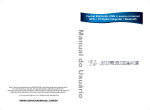
1
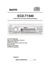
OWNER'S
MANUAL
ECD-T1550
• PLL Synthesizer Stereo Radio
• Digital Compact Disc Player
• Automatic Memory Storing
• Motorized Hidden Panel
• Preset Equalization
• Auxiliary Input Jack
• Credit Card Remote Control
• Multi-Color LCD
• Plays CD-R/RW discs
CONTENTS
Installation......................................3
Repeating the same track ............11
Take out screw before installation ...3
Playing all tracks in random .........11
DIN Front-Mount (Method A) ...........3
Ejecting a disc..............................11
Installing the unit ..........................3
Disc notes........................................11
Removing the unit ........................4
Specification....................................12
DIN Rear-Mount (Method B)............5
Trouble shooting ..............................13
Using the front panel.....................6
Wiring Connection .........................7
Operation........................................8
Switching on/off the unit..................9
Faceplate release ............................9
Sound adjustment ...........................9
Loudness .........................................9
Set the clock....................................9
Mute ................................................9
Equalization .....................................9
Liquid crystal display.......................9
Flashing LED ...................................9
Remote sensor ...............................9
Reset function .................................9
Radio operation ...............................10
Switching to radio mode ..............10
Selecting the frequency band ......10
Selecting station ..........................10
Local/distant ................................10
Automatic memory storing&
program scanning ........................10
Station storing..............................10
Mono/stereo.................................10
CD operation ...................................10
Switching to CD mode .................10
Selecting tracks............................11
Pausing playing............................11
Previewing all tracks ....................11
2
INSTALLATION
Notes:
TAKE OUT SCREW BEFORE
INSTALLATION
• Choose the mounting location where
the unit will not interfere with the normal
activity of the driver.
Before install the unit, please remove the
two screws.
Take out screw before installation
• Before finally installing the unit,
connect the wiring temporarily and
make sure it is all connected up
properly. Test to see if the system is
working properly.
• Use only the parts included with the
unit to ensure proper installation.
The use of unauthorized parts can
cause malfunctions.
DIN FRONT-MOUNT (Method A)
• Consult with your nearest dealer if
installation requires the drilling of holes
or other modifications of the vehicle.
Installation Opening
This unit can be installed in any dashboard
having an opening as show below:
• Install the unit where it does not get in
the driver’s way and cannot injure the
passenger if there is a sudden stop.
53 mm
• If installation angle exceeds 30˚ from
horizontal, the unit might not give its
optimum performance.
182 mm
Installing the unit
Be sure you test all connections first, and
then follow these steps to install the unit.
1. Make sure the ignition is turned off,
and then disconnect the cable from
the vehicle battery's negative (-)
terminal.
2. Disconnect the wire harness and the
antenna.
3. The two supplied keys release tabs
inside the unit's sleeve so you can
remove it. Insert the keys as far as they
will go (with the notches facing up) into
the appropriate slots at the middle left
and right sides of the unit. Then slide
the sleeve off the back of the unit.
30˚
• Avoid installing the unit where it would
be subject to high temperature, such
as direct sunlight, hot air from the
heater, or where it would be
subject to dust, dirt or excessive
vibration.
DIN FRONT/REAR-MOUNT
This unit can be properly installed either
from “Front” (conventional DIN Frontmount) or “Rear” (DIN Rear-mount
installation, utilizing threaded screw holes
at the sides of the unit chassis).
For details, refer to the following
illustrated installation methods.
3
INSTALLATION
metal strap to a solid metal part of the
vehicle under the dashboard. This strap
also helps ensure proper electrical
grounding of the unit.
Sleeve
L Key
Spring Washer
Hex Nut
Metal Strap
Mounting Bolt
R Key
Plain Washer
Tapping Screw
4. Mount the sleeve by inserting the sleeve
into the opening of the dashboard and
bend open the tabs located around the
sleeve with a screwdriver. Not all tabs
will be able to make contact, so
examine which ones will be most
effective. Bend open the appropriate
tabs behind the dashboard to secure
the sleeve in place.
8. Reconnect the cable to the vehicle
battery's negative (-) terminal.
Removing the unit
1. Make sure the ignition is turned off,
then disconnect the cable from the
vehicle battery’s negative (-) terminal.
2. Remove the metal strap attached the
back of the unit (if attached).
3. Insert the release frame key into the
groove at the right side of the frame,
then prize out to remove the frame.
(You can also use the key to remove
the frame from the left side.)
Dashboard
Tabs
Screwdriver
Frame
5. Reconnect the wire harness and the
antenna and be careful not to pinch
any wires or cables.
6. Slide the unit into the sleeve until it
locks into place.
7. To further secure the unit, use the
supplied metal strap to secure the back
of the unit in place. Use the supplied
hardware (Hex Nut (M5mm) and Spring
Washer) to attach one end of the strap
to the mounting bolt on the back of
the unit. If necessary, bend the metal
strap to fit your vehicle's mounting
area. Then use the supplied hardware
(Tapping Screw (5x25mm) and Plain
Washer) to attach the other end of
4. After releasing the frame, insert the
release unit keys supplied with the
accessory into the grooves at both
sides of the unit as shown in figure
until they click. Pulling the keys makes
it possible to remove the unit from the
dashboard.
4
INSTALLATION
DIN REAR-MOUNT (Method B)
3
1
2
4
6
5
Tab
1.
2.
3.
4.
Factory-installed radio bracket
Car radio mounting bracket
Screw
After aligning the car radio mounting
bracket with the factory-installed radio
bracket, tighten the screws (M5x4mm)
at 2 places on each side.
5. When fixing factory-installed radio
bracket with the screws, use a
standard-tipped screwdriver to pry the
tabs of the car radio mounting bracket
to make them fit into the holes in the
factory-installed radio bracket.
6. Movable panel frame
5
USING THE FRONT PANEL
3. Insert a disc in the disc slot, the
panel will automatically turn up to
State 2. Press (eject) button again,
the panel will turn down to eject the
disc. If you don’t insert a disc in
again, the panel will automatically turn
up after 10 seconds. If you don’t
want to wait, press (eject) button,
the panel will also turn up.
1. When the ignition key is switched to
“ACC ON”, the panel of the unit will
change from State 1 to State 2 (see
below), the hidden panel will turn up.
4. When the ignition key is switched to
“ACC OFF”, and there is no portable
audio player connected to the unit
through the AUX IN jack, the front
panel will change from State 2 to State
1.
If there is a portable audio player
connected to the unit through the AUX
IN jack, the front panel will remain
State 2, when the key is switched to
“ACC OFF”.
State 1
State 2
2. Press (power) button to turn on the
unit. Then press (eject) button, the
panel will turn down to horizontal
position (see State 3).
State 3
6
WIRING CONNECTION
4 x 50W System
MAIN UNIT
ANTENNA SOCKET
IGNITION RED
SWITCH (ACC+)
MEMORY
BACK-UP (B+)
GROUND (B–)
YELLOW
(GREY)
BLACK
RCA CABLE
Rch RED
Lch WHITE
POWER
ANTENNA
FRONT Lch
SPEAKER
REAR Lch
SPEAKER
BLUE
WHITE
GREY
WHITE/BLACK
GREY/BLACK
GREEN
VIOLET
GREEN/BLACK
VIOLET/BLACK
7
FRONT Rch
SPEAKER
REAR Rch
SPEAKER
OPERATION
27
10 23 24
11
9
3
14 8
2 1 18 19 20 21 22
5
8
12 4 13
6 16 17 7
15
OPERATION
SWITCHING ON/OFF THE UNIT
When the hidden panel turns up (in State
2), switch the unit on by pressing any
button (except button (4)). When system
is on, press (9) to turn the unit off.
SOUND ADJUSTMENT
Press SEL button (10) to select the
desired adjustment mode.
The adjustment mode will change in
the following order:
VOL
(Volume)
BAS
(Bass)
TRE
(Treble)
BAL
(Balance)
FAD
(Fader)
By pressing VOLUME + button (11) or
VOLUME- button (27), it is possible to
adjust the desired sound quality.
BEEP ADJUSTMENT
Press SEL button (10) and hold for more
than 2 seconds until “BEEP“ appears on
display.
Press VOLUME+ button (11) or
VOLUME- button (27) as follows:
BEEP 2ND
BEEP ALL
BEEP OFF
- BEEP 2ND mode:
The beep is only generated when all
allowed double function button is
pressed long (several seconds). e.g.
When preset button is pressed.
When BND/LOU button (13) is
pressed.
When AMS button (18) is pressed.
- BEEP ALL mode:
The beep is generated when every
button is pressed.
- BEEP OFF mode:
The beep is disabled.
SET THE CLOCK
Press the DSP button (15), the clock is
shown on the LCD display. Then hold down
the button until the clock flashes. Then
press the MANU/SKIP button (17) to
change hours or MANU/SKIP button (16)
to change minutes.
MUTE
Press MUT button (2) to mute down the
sound instantly. If any button (except
button (4)) is pressed in the mute state, the
mute mode is released.
EQUALIZATION
Press EQ button (24) to turn on equalization
function and to select desired audio mode.
There are five kinds of mode as below:
FLAT
CLASSICS
POP M
ROCK M
DSP OFF
LIQUID CRYSTAL DISPLAY
Exhibit current frequency and activated
functions on the display (8).
AUXILIARY INPUT
The unit can be connected to a portable
audio player through the AUX IN jack (7).
Note : The face plate will not close when
something is plugged in the AUX in jack.
REMOTE SENSOR
Point the remote control handset to the
remote sensor IR (23). Press the function
keys on the handset to control the system.
RESET FUNCTION
RESET button (12) can be activated with
either a ballpoint pen or thin metal object.
The RESET button is to be activated for
the following reasons:
- Initial installation of the unit when
all wiring is completed.
- All the function buttons do not
operate.
- Error symbol on the display.
9
OPERATION
RADIO OPERATION
• SWITCHING TO RADIO MODE
Press MOD button (6) shortly to select
radio mode, the radio mode appears
in the display together with the memory
band and frequency.
• AUTOMATIC MEMORY
STORING & PROGRAM SCANNING
- Automatic Memory Storing
Press AMS button (18) for several
seconds, the radio searches from
the current frequency and checks
the signal strength until one cycle
search is finished. The six
strongest stations will be stored into
the corresponding preset number
button.
• SELECTING THE FREQUENCY
BAND
At radio mode, press BND/LOUD
button (13) shortly to select the desired
band.
The reception band will change in the
following order:
FM1
FM2
FM3
- Program Scanning
Press AMS button (18) shortly to
scan preset station stored in memory.
AM
• STATION SELECTION
Press MANU/SKIP + button(17) or
MANU/SKIP -button(16) shortly to
activate automatic seek function.
Press for several seconds until
“MANUAL” appears on the display,
the manual tuning mode is selected.
If both buttons are not pressed for
several seconds, they will return to
seek tuning mode and “AUTO”
appears on the display.
• LOCAL/DISTANT
Press LOC button (3) to select
between local and distant stations.
Local setting for reception of strong
station, and a distant setting for
reception of weaker stations. This
function is in effect during AUTO
SEEK operation.
• STATION STORING
Press any one of the preset buttons
(14) (M1 to M6) to select a station
which had been stored in the memory.
Press this button for several seconds
(until 2’nd beeps come out) to store
current station in that preset button.
• MONO/STEREO
Press MON button (1) to select mono or
stereo mode. You can sometimes
improve reception of distant stations by
selection mono operation.
CD OPERATION
• SWITCHING TO CD MODE
If there is no CD inserted in the player :
When the front panel is in State 2 and
the unit is on, press EJECT button (4),
the panel will change into State 3 and
display the disc slot (5). Gently insert the
CD with the printed side on top into the
CD compartment until you feel some
resistance. The CD is drawn into the
player automatically and the panel will
automatically turn up. CD playback
begins.
10
OPERATION
If a CD is already inserted in the player:
Keep pressing MOD button (6) shortly
until the CD mode display appears.
DISC NOTES
A. Notes on discs:
• Attempting to use non-standard
shape discs (e.g. square, start, heart)
may damage the unit. Be sure to use
round shape CD discs only for this
unit.
• Do not stick paper or tape etc., onto
the label side or the recording side of
any discs, as it may cause a
malfunction.
• Dirt, dust, scratches and warping
discs will cause misoperation.
• SELECTING TRACKS
Press MANU/SKIP -button (16) or
MANU/SKIP+ button(17) to move
to the previous track or the following
track. Track number shows on display.
Hold MANU/SKIP -button (16) or
MANU/SKIP+ button (17) to fast
reverse or fast forward. CD play starts
when you release the button.
• PAUSING PLAYING
Press PAU button (19) to pause CD
player. Press it again to resume play.
B. Notes on CD-Rs (recordable
CDs)/CD-RWs (rewritable CDs):
• Be sure to use discs with following
marks only for the unit to play:
• PREVIEWING ALL TRACKS
Press SCN button (20) to play first
several seconds of each track on the
current disc. Press it again to stop
intro and listen to track.
Recordable
• REPEATING THE SAME TRACK
Press RPT button(21) to
continuously repeat the same track.
Press it again to stop repeat.
Rewritable
• The unit cannot play a CD-R and
CD-RW that is not finalized.
(Please refer to the manual of your
CD-R/CD-RW recorder or CD-R/
CD-RW software for more
information on finalization process).
• Depending on the recording status,
conditions of the disc and the
equipment used for the recording,
some CD-Rs/CD-RWs may not be
played on this unit. (See *)
* To have more reliable play back,
please see following
recommendations:
a.Use CD-RWs with speed 1x to 4x
and write with speed 1x to 2x.
b.Use CD-Rs with speed 1x to 8x and
write with speed 1x to 2x.
c.Do not play a CD-RW which has
been written for more than 5 times.
• PLAYING ALL TRACKS IN
RANDOM
Press SHF button (22)to play all
tracks on CD in random order. Press
again to cancel the function.
• EJECTING A DISC
When the front panel is in State 2 and
there is a disc in the disc slot, Press
button (4), the panel will turn down
and eject the disc from the disc slot
(5).
Note : When you first play a CD and when
whichever track is playing,press M5
button or M6 button,the unit will search
the disc again and start to play the first
track.Later,there is no function of pressing
M5 button or M6 button.
11
SPECIFICATION
GENERAL
Power Supply Requirements
Chassis Dimensions
Tone Controls
- Bass (at 100 Hz)
- Treble (at 10 KHz)
Maximum Output Power
Current Drain
: DC 12 Volts, Negative Ground
: 178 (W) x 165 (D) x 50 (H)
:
:
:
:
± 10 dB
± 10 dB
4 x 50 Watts
15 Ampere (max.)
CD PLAYER
Signal to Noise Ratio
Channel Separation
Frequency Response
: More than 55 dB
: More than 45 dB
: 40 Hz - 18 KHz
RADIO
Frequency Coverage
IF
Sensitivity (S/N=30dB)
Stereo Separation
:
:
:
:
:
FM
87.5 to 107.9
10.7 MHz
4µV
>25dB
Frequency Coverage
IF
Sensitivity (S/N=20dB)
AM
: 530 to 1710 kHz
: 450 kHz
: 36 dBu
12
TROUBLE SHOOTING
Before going through the check list, check wiring connection. If any of the problems
persist after check list has been made, consult your nearest service dealer.
Symptom
No power.
Disc cannot be
loaded or ejected.
Cause
Solution
The car ignition switch is
not on.
If the power supply is properly
connected to the car accessory
circuits, but the engine is not
moving, switch the ignition key
to “ACC”.
The fuse is blown.
Replace the fuse.
Presence of CD disc inside
the player.
Remove the disc in the player,
then put a new one.
Inserting the disc in reverse Insert the compact disc with
direction.
the label facing upward.
No sound.
Sound skips.
Compact disc is extremely
dirty or defective disc.
Clean the disc or try to play a
new one.
Temperature inside the car
is too high.
Cool off or until the ambient
temperature return to normal.
Condensation.
Leave the player off for an hour
or so, then try again.
Volume is in minimum.
Adjust volume to a desired level.
Wiring is not properly
connected.
Check wiring connection.
The installation angle is
more than 30 degrees.
Adjust the installation angle less
than 30 degrees.
The disc is extremely dirty
or defective disc.
Clean the compact disc, then
try to play a new one.
The operation keys The built-in microcomputer
do not work.
is not operating properly
due to noise.
Press the RESET button.
Front panel is not properly fixed
into its place.
The radio does not
work. The radio
station automatic
selection does not
work.
The antenna cable is not
connected.
Insert the antenna cable firmly.
The signals are too weak.
Select a station manually.
13
SANYO MOBILE AUDIO
MODEL ECD-T1550 LIMITED WARRANTY
OBLIGATIONS
In order to obtain warranty service, the product must be delivered to and picked up from an Authorized
Sanyo Factory Service Center at the user’s expense, unless specifically stated otherwise in this
warranty. The names and addresses of Authorized Sanyo Service Centers may be obtained by calling
the toll-free number listed below.
For product operation, authorized service center referral, service assistance or problem resolution, call
CUSTOMER INFORMATION 1-800-421-6382
Weekdays 8:00 AM - 5:00 PM Pacific Time
THIS WARRANTY IS VALID ONLY ON SANYO PRODUCTS PURCHASED AND USED IN THE
UNITED STATES OF AMERICA.
THIS WARRANTY APPLIES ONLY TO THE ORIGINAL RETAIL USER, AND DOES NOT APPLY TO
PRODUCTS USED FOR ANY INDUSTRIAL, PROFESSIONAL OR COMMERCIAL PURPOSE. THE
ORIGINAL DATED BILL OF SALE OR SALES SLIP MUST BE SUBMITTED TO THE AUTHORIZED
SANYO SERVICE CENTER AT THE TIME WARRANTY SERVICE IS REQUESTED.
Subject to the OBLIGATIONS above and EXCLUSIONS below, SANYO FISHER COMPANY (SFC)
warrants this SANYO product against defects in materials and workmanship for the periods specified
below. SFC will repair or replace (at its option) the product and any of its parts which fail to conform
to this warranty with new or reconditioned products or parts. The warranty period commences on the
date the product was first purchased at retail.
LABOR
PARTS
1 YEAR
1 YEAR
EXCLUSIONS
This warranty does not cover (A) the adjustment of customer-operated controls as explained in the
appropriate model’s instruction manual, or (B) the repair of any product whose serial number has been
altered, defaced or removed.
This warranty does not apply to the cabinet or cosmetic parts, knobs or routine maintenance.
This warranty does not apply to the elimination of car static or motor noise, correction of antenna
problems, or damage to compact discs, speakers, accessories or vehicle electrical systems.
This warranty does not apply to repairs or replacements necessitated by any cause beyond the control
of SFC including, but not limited to, any malfunction, defect or failure caused by or resulting from
unauthorized service or parts, improper maintenance, operation contrary to furnished instructions,
shipping or transit accidents, modification or repair by the user, abuse, misuse, neglect, accident,
incorrect power line voltage, fire, flood or other Acts of God, or normal wear and tear.
The foregoing is in lieu of all other express warranties and SFC does not assume or authorize any party
to assume for it any other obligation or liability.
THE DURATION OF ANY WARRANTIES WHICH MAY BE IMPLIED BY LAW (INCLUDING THE
WARRANTIES OF MERCHANTABILITY AND FITNESS) IS LIMITED TO THE TERM OF THIS WARRANTY
IN NO EVENT SHALL SFC BE LIABLE FOR SPECIAL, INCIDENTAL OR CONSEQUENTIAL DAMAGES
ARISING FROM OWNERSHIP OR USE OF THIS PRODUCT, OR FOR ANY DELAY IN THE
PERFORMANCE OF ITS OBLIGATIONS UNDER THIS WARRANTY DUE TO CAUSES BEYOND ITS
CONTROL.
SOME STATES DO NOT ALLOW LIMITATIONS ON HOW LONG AN IMPLIED WARRANTY LASTS
AND/OR DO NOT ALLOW THE EXCLUSION OR LIMITATION OF CONSEQUENTIAL DAMAGES, SO
THE ABOVE LIMITATIONS AND EXCLUSIONS MAY NOT APPLY TO YOU.
THIS WARRANTY GIVES YOU SPECIFIC LEGAL RIGHTS. YOU MAY HAVE OTHER RIGHTS, WHICH
VARY FROM STATE TO STATE.
For your protection in the event of theft or loss of this product, please fill in the information below for
your own personal records.
Model No.
Date of Purchase
Where Purchased
Serial No.
Located on back or bottom side of unit)
Purchase Price
21605 Plummer Street
Chatsworth, CA91311
ECD-T1443. Issue Number 1.
Printed in Hong Kong
88-C1732-01